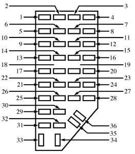
Mazda B-Series (2001) – fuse box diagram
Year of production: 2001
Interior fuse panel

interior fuse panel
| Number | Ampere rating [A] | Description |
| 1 | 5 | Power Mirror |
| 2 | 10 | Blower Motor Relay, Air Bag Diagnostic Monitor, Passive Deactivation (PAD) Module |
| 3 | 7,5 | Trailer Tow Connector (LH Stop/Turn) |
| 4 | — | — |
| 5 | 10 | 4×4 Control Module |
| 6 | — | — |
| 7 | 7,5 | Trailer Tow Connector (LH Stop/Turn) |
| 8 | — | — |
| 9 | 7,5 | Stoplamp Switch |
| 10 | 7,5 | Cruise Control Servo/Amplifier Assy., GEM/CTM, Shift Lock Actuator, Blend Door Actuator, A/C Heater Control Assy., Turn Signals |
| 11 | 7,5 | Instrument Cluster, Main Light Switch, RABS Resistor |
| 12 | — | — |
| 13 | 20 | Brake Pedal Position Switch |
| 14 | 20 | RABS Module |
| 10 | 4WABS Mod., 4WABS Main Relay | |
| 15 | — | — |
| 16 | 30 | W/W Motor, Wiper Hi-Lo Relay, Wiper Run/Park Relay, Washer Pump Relay |
| 17 | 25 | Cigar Lighter, Data Link Connector (DLC) |
| 18 | — | — |
| 19 | 25 | PCM Power Diode, Ignition, PATS |
| 20 | 7,5 | GEM/CTM, Radio |
| 21 | 20 | Flasher |
| 22 | 20 | Auxiliary Power Point |
| 23 | — | — |
| 24 | 7,5 | Clutch Pedal Position (CPP) Switch, Starter Interrupt Relay |
| 25 | — | — |
| 26 | 10 | Battery Saver Relay, 4×4 Electronic Shift Relay, Interior Lamp Relay, 4×4 Elec. Shift Control Module, Dome/Map Lamp, Instrument Illumination Dimming Module, Restraint Control Module, GEM/CTM, Instrument Cluster |
| 27 | — | — |
| 28 | 7,5 | GEM/CTM System, Radio |
| 29 | 15 | Radio |
| 30 | — | — |
| 31 | — | — |
| 32 | — | — |
| 33 | 15 | Headlights, DRL Module, Instrument Cluster |
| 34 | — | — |
| 35 | 15 | ISA Horn Relay if not Equipped with Truck Security Module |
| — | — | |
| 36 | — | — |
Engine compartment fuse block
engine compartment
| Number | Ampere rating [A] | Description |
| 1 | 50 | I/P Fuse Panel |
| 2 | — | — |
| 3 | — | — |
| 4 | — | — |
| 5 | — | — |
| 6 | 50 | ABS Pump Motor |
| 7 | 30 | Powertrain Control Module |
| 8 | 20 | Power Door Locks and Remote Entry |
| 9 | — | — |
| 10 | — | — |
| 11 | 50 | Starter Relay Ignition Switch |
| 12 | 10 | PCM Memory |
| 13 | 20 | 4×4 Motor |
| 14 | — | — |
| 15 | — | — |
| 16 | 40 | Blower Motor |
| 17 | — | — |
| 18 | — | — |
| 19 | — | — |
| 20 | — | — |
| 21 | 10 | PCM Memory |
| 22 | — | — |
| 23 | 20 | Fuel Pump Motor |
| 24 | 30 | Headlights |
| 25 | 10 | A/C Clurtch |
| 26 | — | — |
| 27 | — | — |
| 28 | 30 | 4WABS Module |
| 29 | — | — |
| 30 | 15 | Trailer Tow |
| 31 | 20 | Fog Lamps, Day Time Running Lamps (DRL) |
| 32 | — | — |
| 33 | 15 | Park Lamp |
| 34 | — | — |
| 35 | — | — |
| 36 | — | — |
| 37 | — | — |
| 38 | 10 | Left Headlamp Low Beam |
| 39 | — | — |
| 40 | — | — |
| 41 | — | Heated Oxygen Sensors |
| 42 | 10 | Right Headlamp Low Beam |
| 43 | — | — |
| 44 | — | — |
| 45A | — | Wiper High/Low |
| 45B | — | Wiper Park/Run |
| 46A | — | — |
| 46B | — | Front Washer Pump |
| 47A | — | — |
| 47B | — | — |
| 48A | — | Fog Lamp |
| 48B | — | Fog Lamp Relay |
| 49 | — | Full Starter |
| 50A | — | — |
| 50B | — | Fuel Pump |
| 51 | — | — |
| 52 | — | — |
| 53 | — | Powertrain Control Module (PCM) Diode |
| 54 | — | Powertrain Control Module (PCM) Diode |
| 55 | — | Blower |
| 56A | — | A/C Clutch Solenoid |
| 56B | — | Trailer Tow |
WARNING: Terminal and harness assignments for individual connectors will vary depending on vehicle equipment level, model, and market.