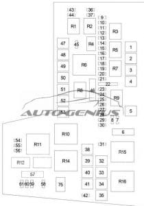
Mitsubishi Raider (2005 – 2009) – fuse box diagram
Year of production: 2005, 2006, 2007, 2008, 2009
Fuse box diagram

| No. | A | Circuits |
| 1 | — | — |
| 2 | 40 | ←’07: Ignition Switch (Windows/Door Lock Circuit Breaker, Fuse: “22”) |
| 3 | 30 | Brake Provision Module |
| 4 | 50 | Driver Seat Switch |
| 5 | 40 | ←’07: Ignition Switch (Rear Window Defogger Relay, Fuse: “57”, “58”, “59”, “60”, “61”) |
| 6 | 20 | Radio, Cluster, Electronic Overhead Module, Satellite Receiver, Front Control Module, Cabin Compartment Node (CCN) |
| 7 | 10 | Powertrain Control Module, Air Conditioner Compressor Clutch Relay, Fuel Pump Relay, Sentry Key Remote Entry Module, Fuse: “8”, “46” |
| 8 | 10 | Cluster, Transfer Case Selector Switch, Inside Rearview Mirror, Cabin Compartment Node (CCN) |
| 9 | 10 | ←’07: Occupant Classification Module |
| 10 | 20 | ’07→: Ignition Switch (Sentry Key Remote Entry Module) |
| 11 | 10 | Air Conditioner Compressor Clutch Relay |
| 12 | 15 | Left Trailer Tow Relay |
| 13 | 15 | Right Trailer Tow Relay |
| 14 | 20 | ←’07: Data Link Connector, Hands-Free Module, Sentry Key Remote Entry Module, Electronic Overhead Module |
| 15 | 25 | Transmission Control Relay, Powertrain Control Module |
| 16 | 20 | Horn Relay |
| 17 | 20 | ABS (Valves) |
| 18 | 20 | Fuel Pump Relay |
| 19 | 15 | Stop Lamp Switch, Center High-Mounted Stop Light (CHMSL) |
| 20 | 20 | Cluster, Door Locks, Cabin Compartment Node (CCN), Shift Motor/Mode Sensor Assembly (4WD), Brake Transmission Shift Interlock (BTSI) |
| 21 | 15 | ←’07: Audio Amplifier |
| 25 | ’07→: Audio Amplifier | |
| 22 | 20 | Power Outlet – Instrument Panel |
| 23 | 20 | Fog Lamp Relay |
| 24 | 20 | Powertrain Control Module |
| 25 | 15 | Cluster, Cabin Compartment Node (CCN) Illumination |
| 26 | 20 | ’07→: Run/Start Relay |
| 27 | 10 | Mirror Switch |
| 28 | 20 | Power Outlet – Console |
| 29 | 20 | Wipers, Front Control Module (FCM) |
| 30 | — | — |
| 31 | 30 | ’07→: Ignition ACC Relay (Window/Door Lock Circuit Breaker (Power Window, Door Lock, Sunroof, Subwoofer Amplifier), Fuse: “22”) |
| 32 | 30 | Front Control Module (Exterior Lights No.1) |
| 33 | 30 | Automatic Shut Down Relay (Powertrain Control Module, Ignition Coil, Fuel Injector, Ignition Capacitor) |
| 34 | 30 | Front Control Module (Exterior Lights No.1) |
| 35 | 40 | Blower Motor Relay (Heating Ventilation Air Conditioning) |
| 36 | 10 | ←’07: Powertrain Control Module, Ignition Unlock/Run/Start |
| 37 | 10 | ←’07: Starter Relay |
| 38 | 20 | ←’07: Ignition Switch |
| 39 | 30 | Starter Solenoid, Powertrain Control Module, Front Control Module, Starter Relay |
| 40 | 40 | ’07→: Ignition RUN Relay |
| 41 | 30 | Wipen On/Off Relay, Wiper High/Low Relay |
| 42 | 25 | Front Control Module (Transfer Case) |
| 43 | 10 | Park/Turn Lamp – Front Left, Tail/Stop/Turn Lamp – Left |
| 44 | 10 | Park/Turn Lamp – Front Right, Tail/Stop/Turn Lamp – Right |
| 45 | 20 | Trailer Tow |
| 46 | 10 | Occupant Restraint Controller Module, Passenger Airbag On/Off Indicator Lamp, Occupant Classification Module (←’07) |
| 47 | 40 | ←’07: Ignition Switch (Cluster) |
| 48 | 20 | Sunroof/Sound Box |
| 49 | 30 | Trailer Tow |
| 50 | 40 | Anti-Lock Brake System (ABS) Module (Pump) |
| 51 | 40 | Park Lamp Relay (Fuse: “43”, “44”, “45”), Front Control Module |
| 52 | — | — |
| 53 | 40 | Rear Window Defogger Relay (Rear Window Defogger, Fuse: “56”) |
| 54 | — | — |
| 55 | 10 | ←’07: Cluster |
| 56 | 10 | Heated Mirrors |
| 57 | 20 | Occupant Restraint Controller Module |
| 58 | 20 | Heated Seat |
| 59 | 10 | Heating Ventilation Air Conditioning (HVAC) Module, A/C Heater Control, Rear Window Defogger Relay |
| 60 | 10 | Anti-Lock Brake System (ABS) Module |
| 61 | 20 | Front Control Module (Reverse Lamps) |
| Relay | ||
| R1 | — | Right Trailer Tow |
| R2 | — | Left Trailer Tow |
| R3 | — | Air Conditioner Compressor Clutch |
| R4 | — | Horn |
| R5 | — | Transmission Control |
| R6 | — | Park Lamp |
| R7 | — | Fuel Pump |
| R8 | — | Fog Lamp |
| R9 | — | — |
| R10 | — | Rear Window Defogger |
| R11 | — | ’07→: Ignition – RUN |
| R12 | — | Wiper High/Low |
| R13 | — | Wiper On/Off |
| R14 | — | Starter |
| R15 | — | Automatic Shut Down |
| R16 | — | ’07→: Blower Motor |
| 75 | — | ’07→: Ignition – ACC |
WARNING: Terminal and harness assignments for individual connectors will vary depending on vehicle equipment level, model, and market.
