Nissan Almera (2000 – 2006) – fuse box diagram
Year of production: 2000, 2001, 2002, 2003, 2004, 2005, 2006
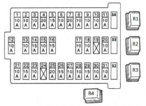
Passenger Compartment Fuse Box
Front side

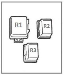
Rear side

| № | A | Component |
|---|---|---|
| 1 | 10A | Mirrors |
| 2 | 10A | Brake lights |
| 3 | 15A | Socket |
| 4 | 7,5A | For additional electronic equipment |
| 5 | 15A | Alarms and indicators |
| 6 | 10A | Additional electric equipment |
| 7 | 20A | Rear window defogger |
| 8 | 10A | Oxygen Sensor |
| 9 | 10A | Additional electronic equipment |
| 10 | 10A | Electronic equipment |
| 11 | 10A | Automatic Transmission |
| 12 | 10A | ECU (turn signals, backlight and main power to the instrument panel, panel lighting) |
| 13 | 10A | Interior lamp |
| 14 | 15A | Interior fan (heater / air conditioning) |
| 15 | 10A | Air Conditioner |
| 16 | 15A | Fan (heater / air conditioner) |
| 17 | 10A | Fuel Injection System |
| 18 | 10A | Airbags |
| 19 | 20A | Additional electric equipment |
| 20 | 10A | Engine module |
| 21 | 10A | Start signal |
| 22 | 15A | Cigarette lighter |
| 23 | – | Not used |
| 24 | 20A | Additional electric equipment |
| 25 | 20A | Windshield wipers |
| 26 | 7,5A | Additional electric equipment |
| 27 | 15A | Front and/or rear window washer (on the stalk switch) |
| 28 | 15A | Rear window washer |
| 29 | 15A | Fuel pump |
| 30 | 10A | Speedometer, tachometer, temperature and fuel level indicators |
| 31 | 10A | ABS |
| 32 | 10A | Reserve |
| 33 | 15A | Reserve |
| 34 | 20A | Reserve |
| Front side relay | ||
| R1 | Headlight relay | |
| R2 | Throttle Control Relays | |
| R3 | Power windows relay | |
| R4 | Rear fog light relay | |
| Rear side relay | ||
| R1 | Ignition relay | |
| R2 | The supercharger relay | |
| R3 | Additional equipment relay (electrical accessories) | |
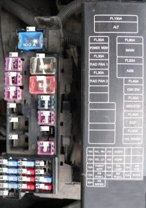
Engine compartment fuse panel

| № | A | Component |
|---|---|---|
| A | 100A | Generator (battery charging) |
| B | 40A | Power windows |
| C | 40A | Cooling fans |
| D | 40A | Cooling fans |
| E | 30A | For diesel engines |
| F | 60A | For diesel engines |
| G | 80A | For diesel engines |
| H | 80A | Main power supply, grounding circuit |
| I | 50A | ABS |
| J | 30A | To the battery ignition switch |
| K | 30A | ABS/ESP |
| L | 30A | ESP |
| M | 30A | Headlight washer |
| 32 | 20A | Rear window washer |
| 33 | 15A | Fog lights |
| 34 | 15A | Electric drive and throttle actuator relay |
| 35 | 15A | Headlamps, daytime running light |
| 36 | 15A | Headlamps, daytime running light |
| 37 | 10A | Rear fog light |
| 38 | 10A | Parking lights, license plate lighting |
| 39 | 10A | Horn, battery charging |
| 40 | 15A | Audio, navigation, LCD display |
| 41 | 10A | Engine management system |
| 42 | 10A | Ignition coil |
| 43 | 15A | Not used |
| 44 | 10A | Not used |
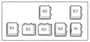
Relay block

| № | Relay |
|---|---|
| R1 | Cooling fan relay 3 (25221E) |
| R2 | Front fog lights (25224QA) |
| R3 | Air conditioner relay E6 (25224D) |
| R4 | Horn relay (25620) |
| R5 | Cooling fan relay (25224J) |
| R6 | Lights (25224A) |
| R7 | Starter (25224G) |
WARNING: Terminal and harness assignments for individual connectors will vary depending on vehicle equipment level, model, and market
