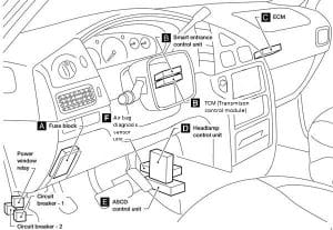
| Fuse |
[A] |
Protected Component |
| 1 |
7,5 |
Front Heated Seats |
| 2 |
10 |
Transmission Control Module (TCM), Rear Wiper Motor, EATC Unit |
| 3 |
10 |
Air Bag Diagnosis Sensor Unit |
| 4 |
10 |
IACV-AAC Valve, Vacuum Cut Valve Bypass Valve, Engine Control Module (ECM), Data Link Connector, Map/Baro Switch Solenoid Valve, Throttle Position Sensor, EVAP Canister Vent Control Valve |
| 5 |
7,5 |
Door Mirror Remote Control Switch, SECU |
| 6 |
20 |
Cigarette Lighter |
| 7 |
20 |
Rear Power Point |
| 8 |
20 |
Front Wiper Motor, Front Washer Motor, Front Wiper Amplifier |
| 9 |
10 |
Rear Wiper Motor, Rear Washer Motor |
| 10 |
15 |
’01-’02: Audio, Video Monitor, Subwoofer Amplifier |
|
7,5 |
’98-’00: Audio |
| 11 |
20 |
’01-’02: Rear Power Point (Console Mounted) |
|
20 |
’98-’00: Subwoofer Amplifier |
| 12 |
7,5 |
Headlamp Control Unit, Engine Control Module (ECM) |
| 13 |
7,5 |
Air Conditioner Control Unit, Air Conditioner Relay, EATC Unit, Air Mix and Mode Door, IACC-FICD Solenoid Valve |
| 14 |
20 |
Rear Window Defogger |
| 15 |
20 |
Rear Window Defogger |
| 16 |
10 |
Rear Window Defogger Switch, Mirror Heaters |
| 17 |
10 |
Front Side Marker Lamps, Front Combination Lamp, Combination Switch |
| 18 |
7,5 |
Illumination Lamps |
| 19 |
10 |
Rear Combination Lamp, Trailer License Lamp |
| 20 |
10 |
Audio, CD Changer, Rear Audio Remote Control Unit, FES Control Panel |
| 21 |
15 |
Interior Lamps, Memory Seat and Mirror Control Unit, Sunroof Motor |
| 22 |
20 |
Stop Lamp Switch, Trailer Tow Control Unit |
| 23 |
10 |
Hazard Switch, Security Indicator Lamp |
| 24 |
15 |
Rear Blower Motor |
| 25 |
15 |
Rear Blower Motor |
| 26 |
7,5 |
Heated Oxygen Sensor |
| 27 |
10 |
Hazard Switch |
| 28 |
20 |
Front Blower Motor, Front Blower Speed Control Unit |
| 29 |
10 |
Data Link Connector, Combination Meter, ASCD Brake Switch, Air Conditioner Relay, Cooling Fan Relay, Rear Blower Motor Relay, Memory Seat and Mirror Control Unit, ASCD Control Unit |
| 30 |
10 |
ABS Actuator and Electric Unit, Park/Neutral Position Switch, Headlamp Control Unit, SECU, Transmission Control Module (TCM) |
| 31 |
20 |
Front Blower Motor, Front Blower Speed Control Unit |
| 32 |
— |
— |
| Relay |
| R1 |
|
Tail Lamp |
| R2 |
|
Ignition |
| R3 |
|
Accessory |
| R4 |
|
Rear Window Defogger |
| R5 |
|
Blower |
