Oldsmobile Silhouette (1993 – 1994) – fuse box diagram
Year of production: 1993, 1994
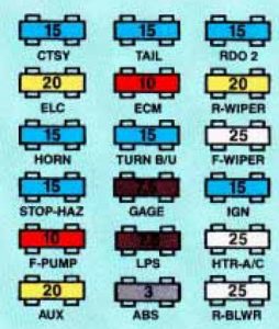
Fuse panel (3.1L V6 ENGINE)

fuse box – engine 3.1 V6
| Position | Ampere rating [A] | Circuity |
| CTSY | 15 | Dome Lamps, Courtesy Lamps, Power Door Lock Switches, Glove Box Lamp, Power Mirrors, Power Sliding Delay Lock Module |
| ELC | 20 | Auto Level Control, Underhood Lamp |
| HORN | 15 | Horns. Horn Relay, Safety Belt Buzzer |
| STOP HAZ | 15 | Front/Rear Turn Lamps, Front Side Marker Lamps, Rear Stop Lamps, Instrument Cluster Turn Indicator Lamps, Cruise Brake Switch |
| F PUMP | 10 | Fuel Pump, Oil Pressure Sender/Fuel Pump Switch |
| AUX | 20 | Radio, Front Cigar Lighter, Accessory Power Outlet |
| TAIL | 15 | Front Park Lamps. Rear Tail Lamps, Front Side Marker Lamps, License Plate Lamp, Radio, Heat/Vent/AC Control Head, Power Sliding Door |
| ECM | 10 | Throttle Body Fuel Injection, Fuel Pump Relay, Elec. Vac. Reg. Valve, Elec. Control Module, Elec. Spark Control Module |
| TURN B/U | 15 | Front/Redr Turn Lamps, Front Side Marker Lamps, Cluster Turn Telltale, Back-up Lamps, Fog Lamps |
| GAGE | 7,5 | Cluster, Anti-Lock Brake System Lamp Module, Elec. Level Control Sensor |
| LPS | 7,5 | Cluster, Radio, Wiper Switch, Headlamp Switch, Rear Blower Switch, Heat/Vent/AC Control Head, Door Switch Illumination. Front/Rear Ashtray Illumination Bulbs |
| ABS | 3 | Anti-Lock Brake System |
| RD02 | 15 | Radio |
| R/WIPER | 20 | Rear WipedWasher Motors; Overhead Console Compass |
| F/WIPER | 25 | Front Wiper/Washer Motor |
| IGN | 15 | A/C Compressor, A/C Solenoid Box, Compressor Relay, Temp. Door Motor, Low Blower Relay; Heat/Vent/AC Control Head; Cruise Module; Cooling Fan Relay; Rear Defogger Relay; Key Chime; Vehicle Speed Sensor Buffer and Generator Charge Discrete, Transaxle Converter Clutch Switch |
| HTR A/C | 25 | Front/Rear Blower Motors, High Blower Relay |
| RR BLWR | 25 | Rear Blower, Rear Heat/Vent/AC |
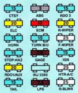
Fuse panel (3800 v6 ENGINE)

fuse box – engine 3800 V6
| Position | Ampere rating [A] | Circuity |
| CTSY | 15 | Dome Lamps, Courtesy Lamps, Power Door Lock Switches, Glove Box Lamp, Power Mirrors, Power Sliding Delay Lock Module |
| ELC | 20 | Auto Level Control, Underhood Lamp |
| HORN | 15 | Horns. Horn Relay, Safety Belt Buzzer |
| STOP HAZ | 15 | Front/Rear Turn Lamps, Front Side Marker Lamps, Rear Stop Lamps, Instrument Cluster Turn Indicator Lamps, Cruise Brake Switch |
| RDOl/AUX | 20 | Radio, Front Cigar Lighter, Accessory Power Outlet |
| TAIL | 15 | Front Park Lamps, Rear Tail Lamps, Front Side Marker Lamps, License Plate Lamp, Radio, Heat/Vent/AC Control Head, Power Sliding Door |
| ABS | 3 | Anti-Lock Brake System |
| ECM | 10 | Mass Air Flow Sensor, Electronic Control Module |
| TURN B/U | 15 | Front/Rear Turn Lamps, Front Side Marker Lamps, Cluster Turn Telltale, Back-up Lamps, Fog Lamps |
| GAGE | 7,5 | Cluster, Anti-Lock Brake System Lamp Module, Elec. Level Control Sensor |
| LPS | 7,5 | Cluster, Radio, Wiper Switch, Headlamp Switch, Rear Blower Switch, HeatlVentiAC Control Head, Door Switch Illumination, Front/Rear Ashtray Illumination Bulbs |
| RDO2 | 15 | Radio |
| R/WIPER | 20 | Rear Wiper/Wdsher Motors; Overhead Console Compass |
| F/WIPER | 25 | Front Wiper/Washer Motor |
| IGN | 15 | A/C Solenoid Box, Temp. Door Motor, Low Blower Relay; Heat/Vent/AC Control Head; Cooling Fan Relay; Rear Defogger Relay; Key Chime; Transaxle Converter Clutch Solenoid and Generator Charge Discrete |
| HTR A/C | 25 | Front/Rear Blower Motors, High BlowerR elay |
| RR BLWR | 25 | Rear Blower, Rear Heat/Vent/AC |
Circuit breaker/relay panel
Circuit breaker/relays are locatted in thr circuit breaker/relay panel. This is located behind the panel under the glove box, near the passengers’s door.

fuse box – circuit breaker/relay panel
| Position | Ampere rating [A] | Circuity |
| 1 | Hazard Flasher | |
| 2 | 15 | With 3800 V6 engine only: Canister Purge Solenoid, A/C Clutch Control Relay, Cruise Control |
| 3 | Not Used | |
| 4 | 30 | Power Windows Circuit Breaker |
| 5 | 30 | Power SeatIPower Sliding Door Motor Circuit Breaker |
| 6 | 30 | Rear Defogger Circuit Breaker |
| 7 | Air Conditioning Blower Relay | |
| 8 | Horn Relay | |
| 9 | Chime Module | |
| 10 | Defogger Timer Relay |
WARNING: Terminal and harness assignments for individual connectors will vary depending on vehicle equipment level, model, and market.
