Opel GT (2007 – 2009) – fuse box diagram
Year of production: 2007, 2008, 2009
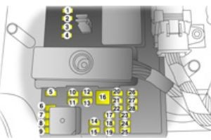
Fuse box in passenger compartment
The fuse box is located at the end of the passenger’s foot well, below the instrument panel. Pull floor carpet from the top to access fuse box cover. To open, pull cover from the left-hand side to detach from Velcro pads and remove cover.

| Number | Circuit | Rating |
| 1 | — | — |
| 2 | — | — |
| 3 | — | — |
| 4 | — | — |
| 5 | Amplifier | 20 |
| 6 | Instrument panel cluster | 10 |
| 7 | Ignition switch, electronic immobiliser | 2 |
| 8 | Brake lamp | 10 |
| 9 | Climate control, electronic immobiliser | 10 |
| 10 | — | — |
| 11 | Spare | 20 |
| 12 | Airbags | 10 |
| 13 | Spare | 10 |
| 14 | Windscreen wipers | 10 |
| 15 | Climate control, seat occupancy recognition, clutch switch, crank relay, instrument panel cluster | 10 |
| 16 | Electric windows | 30 |
| 17 | — | — |
| 18 | — | — |
| 19 | Steering wheel controls | 2 |
| 20 | Spare | 15 |
| 21 | Spare | 20 |
| 22 | — | — |
| 23 | Radio | 15 |
| 24 | Sensing and Diagnostic Module | 10 |
| 25 | Engine Control Module, Transmission Control Module | 10 |
| 26 | Door locks | 15 |
| 27 | Interior lamps | 10 |
| 28 | Steering wheel control illumination | 2 |
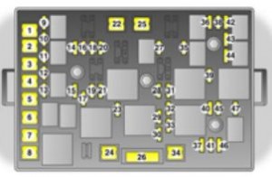
Fuse box in engine compartment
To open the cover, press locking tabs at each end of the fuse box inwards. Lift the cover upwards to remove.

| Number | Circuit | Rating |
| 1 | — | — |
| 2 | Body Control Module | 50 |
| 3 | Body Control Module 2 | 40 |
| 4 | Crank | 30 |
| 5 | Body Control Module 3 | 30 |
| 6 | — | — |
| 7 | Heated rear window | 20 |
| 8 | Cooling fan | 60 |
| 9 | Fuel pump | 15 |
| 10 | — | — |
| 11 | Luggage compartment | 5 |
| 12 | Luggage compartment | 25 |
| 13 | — | — |
| 14 | Electric exterior mirrors | 5 |
| 15 | Spare | 10 |
| 16 | — | — |
| 17 | Air conditioning | 10 |
| 18 | Data link connector | 15 |
| 19 | Spare | 20 |
| 20 | — | — |
| 21 | Outlet | 20 |
| 22 | — | — |
| 23 | Emissions | 10 |
| 24 | Vacuum pump | 20 |
| 25 | — | — |
| 26 | Electric seat | 20 |
| 27 | — | — |
| 28 | Engine Control Module, transmission | 15 |
| 29 | Engine Control Module | 20 |
| 30 | Turbo, Cam phaser | 10 |
| 31 | — | — |
| 32 | Reversing lamp | 10 |
| 33 | Ignition coils | 15 |
| 34 | ABS | 10 |
| 35 | Fog lamps | 15 |
| 36 | Horn | 15 |
| 37 | Remote central locking | 10 |
| 38 | Driver’s side high beam | 10 |
| 39 | Windscreen wipers | 25 |
| 40 | ABS | 10 |
| 41 | ABS | 20 |
| 42 | Passenger’s side high beam | 10 |
| 43 | Passenger’s side low beam | 10 |
| 44 | Driver’s side low beam | 10 |
| 45 | Instrument panel ignition | 20 |
| 46 | Canister vent | 10 |
| 47 | Parking lamps | 15 |
WARNING: Terminal and harness assignments for individual connectors will vary depending on vehicle equipment level, model, and market.
