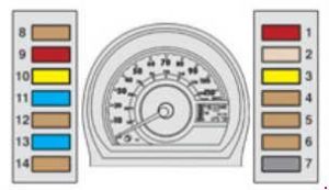
Peugeot 107 (from 2005) – fuse box diagram
Year of production: 2005, 2006, 2007, 2008, 2009, 2010, 2011, 2012, 2013, 2014, 2015, 2016, 2017, 2018
Instrument panel fuse boxes

| № |
A |
Functions |
| 1 | 10 | Brake lamps – ABS – 2 Tronicgearbo |
| 2 | 25 | Central locking/unlocking – Remote control |
| 3 | 20 | Rear screen demisting |
| 4 | 7.5 | Rear lamps – Number plate lamps – Instrument panel – Screen – headlamp adjustment – LED daytime runninglamps -Sidelamps |
| 5 | 7.5 | Diagnostic socket |
| 6 | 7.5 | 2 Tronicgearbox – Rearfoglamp – ESP – LED daytime runninglamps – Instrument panel – Rev counter |
| 7 | 7.5 | Demisting |
| 8 | 7.5 | ABS/ESP – Power steering- Fan assembly |
| 9 | 10 | Reversinglamps – Central locking/unlocking – Electric windows – Rear screen demisting – Speedometer – Airconditioning – Heating – Rev counter – Remote control |
| 10 | 20 | Front and rear wipers and screenwash |
| 11 | 15 | Audio equipment – 12 V socket (120 W max) |
| 12 | 7.5 | Heated rear screen – ABS – Fan assembly – Front and rear wipers and screenwash – Power steering – Central locking/unlocking – Air conditioning- Heating – Electric windows – Speedometer – Rev counter – Remote control – Reversinglamp |
| 13 | 15 | Airbag – Fuel injection system – 2 Tronicgearbox – Instrument panel – Rev counter – LED daytime runninglamps |
| 14 | 7.5 | Air conditioning – Heating |
| 15 | 40 | Audio system – 12 V socket – Front and rear wipers – Power steering – ABS/ESP – Coolingfan assembly |
| 16 | 30 | Electric windows |
| 17 | 40 | Air conditioning – Heating |
Engine compartment fuse box
2005-2012
2012-
| № |
A |
Functions |
| 1 | 5 | LED daytime running lamps |
| 2 | 20 | Front foglamps |
| 3 | 10 | Left hand front lamp |
| 4 | 10 | Right hand front lamp |
| 5 | 7.5 | 2 Tronic gearbox – Fuel injection system |
| 6 | 7.5 | 2 Tronic gearbox – Fuel injection system |
| 7 | 30 | LED daytime running lamps – Front foglamps |
| 8 | 25 30 |
ABS ABS/ESP (with VSC) |
| 9 | 30 | Starter motor – Heated rear screen – ABS – Coolingfan assembly – Front and rear wipersand screenwash – Power steering – Centrallocking/unlocking – Air conditioning – Heating – Electric windows – Speedometer – Rev counter – Remote control – Reversinglamp – Airbag – Fuel injection system – 2 Tronic gearbox – Instrument panel – LEDdaytime runninglamps |
| 10 | 10 | Hazard warning lamps – Instrument panel – Rev counter – Direction indicators |
| 11 | 20 | Left hand front lamp – Right hand front lamp |
| 12 | 15 | Courtesy lamp – Speedometer – Audiosystem – Instrument panel – Rev counter |
| 13 | 15 | Fuel injection system – Cooling fan assembly |
| 14 | 10 | Horn |
| 15 | 7.5 | Replacement fuse |
| 16 | 10 | Replacement fuse |
| 17 | 15 | Replacement fuse |
| 18 | 50 | 2 Tronic gearbox |
| 19 | 30/40 | Cooling fan assembly |
| 20 | 40 50 |
ABS ABS/ESP (with VSC) |
| 21 | 50 | Power steering |
WARNING: Terminal and harness assignments for individual connectors will vary depending on vehicle equipment level, model, and market.