Renault Magnum (2001 – 2005) – fuse box diagram
Year of production: 2001, 2002, 2003, 2004, 2005
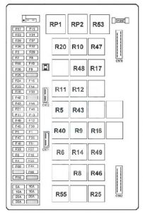
Fuse box

| Function | Number | Ampere rating [A] |
| Trailer socket, 7-pin type “EBS” Trailer socket, 7-pin type 24 S Engine preheating control Electric or hydraulic retarder control |
F1 | 10 |
| RH side/parking lights RH marker lights RH central marker lights |
F2 | 10 |
| LH side/parking lights LH marker lights LH central marker lights |
F3 | 10 |
| Trailer side/parking lights | F4 | 10 |
| Available power supply (lighting) Available power supply (roof light bank) |
F5 | 10 |
| Dashboard instruments lighting Switch lighting Headlamps wash time-delay relay |
F6 | 10 |
| Fog light(s) Fog lights warning light |
F8 | 10 |
| Fog driving lights Fog driving lights warning light |
F9 | 10 |
| RH main beam headlight | F10 | 10 |
| LH main beam headlight Main beam headlights warning light |
F11 | 10 |
| LH dipped beam headlight Dipped beam headlights warning light |
F12 | 10 |
| RH dipped beam headlight | F13 | 10 |
| Windscreen wiper relay Anti-theft alarm ECU |
F15 | 10 |
| Anti-theft electronic box “AIRBAG” ECU Defrosting rearview mirror control Air pressure gauge Reversing buzzer |
F16 | 10 |
| Air conditioning | F18 | 20 |
| “EBS” ECU | F20 | 20 |
| Power supply (after master switch) | F21 | 15 |
| Independent heater Ventilation control box Independent heater programming control Main water circuit solenoid valve 3-level air conditioning pressure controller Air conditioning relay |
F22 | 30 |
| Step light Overhead light(s) Voltage dropper (telecommunications) Map reader |
F23 | 20 |
| Gearbox ECU “ASTRONIC” | F24 | 20 |
| Tachograph clock | F25 | 5 |
| Trailer socket, 7-pin type “EBS” | F26 | 20 |
| Stop lights Trailer stop lights |
F27 | 10 |
| Hydraulic retarder ECU | F28 | 10 |
| LH swivelling defrosting rearview mirror RH swivelling defrosting rearview mirror |
F29 | 10 |
| Headlamps adjustment motors Radio |
F30 | 10 |
| Windscreen wiper motor Windscreen washer pump Headlamps washer pump |
F32 | 20 |
| Diagnostics socket Suspension ECU |
F33 | 10 |
| Radio tuner + 24 Volts power supply Independent heater programming control Anti-theft alarm siren |
F34 | 10 |
| Available power supply (after ignition key) | F35 | 10 |
| Horn 2-tone horn solenoid valve Self-tracking axle electrovalve Roof air vent motor |
F37 | 20 |
| Principal display | F38 | 5 |
| Available relay(s) | F40 | 10 |
| Gearbox ECU “ASTRONIC” | F42 | 10 |
| Trailer + 24 Volts power supply Onboard management prearrangement Working spotlamp (tractor) |
F43 | 15 |
| Cab tilt pump | F44 | 30 |
| Passenger side electric door striker Driver side electric door striker Flasher unit Hazard lights control Doors central locking box Anti-theft alarm ECU |
F45 | 20 |
| Air dryer heater Centralized lubrication timer Self-tracking axle safety relay |
F46 | 20 |
| Suspension ECU Suspension remote control box Rear drive axle air springs pressure sensor |
F47 | 10 |
| Reversing lights relay | F49 | 10 |
| Refrigerator | F50 | 20 |
| Heated driver’s seat Heated passenger seat Voltage dropper (12V socket) “SAE” plug socket Cigar lighter Refrigerant cylinder-holder |
F51 | 20 |
| Video available power supply | F53 | 10 |
| Front sun blind motor Side sun blind motors |
F54 | 10 |
| Available power supply (after ignition key) Available relay(s) |
F55 | 10 |
| Window winder motor | F56 | 20 |
| Vehicle master ECU Tachograph |
F57 | 10 |
| “EUP” ECU Exhaust brake electrovalve |
F58 | 20 |
| “EBS” ECU | F60 | 5 |
| Hydraulic retarder ECU Electric retarder ECU |
F86 | 10 |
Table of relays on connection unit
| Function | Number | Ampere ratting [A] |
| After ignition power supply relay № 1 | RP1 | 50 |
| After ignition power supply relay № 2 | RP2 | 50 |
| Side / parking lights relay | R5 | 20 |
| Comfort accessories relay | R6 | 20 |
| Lighting relay | R8 | 20 |
| Fog driving lights relay | R9 | 20 |
| Fog lights relay | R10 | 20 |
| Dipped beam headlights relay | R11 | 20 |
| Main beam headlights relay | R12 | 20 |
| Stop lights relay | R14 | 20 |
| Preheating relay № 2 | R16 | 20 |
| Available relay № 1 | R17 | 20 |
| Defrosting rearview mirrors relay | R20 | 20 |
| Windscreen wiper relay | R40 | 20 |
| Reversing lights relay | R40 | 20 |
| “VECU / EECU” ECU power supply relay | R43 | 20 |
| Air conditioning compressor relay | R46 | 20 |
| Available relay № 2 | R47 | 20 |
| Available relay № 3 | R48 | 20 |
| Conditioned air relay | R49 | 20 |
| Headlamp washer time-delay relay | R53 | — |
| Self-tracking axle safety relay | R55 | 20 |
Table of relays away from connection unit
| Function | Number | Ampere ratting [A] |
| Preheating relay | R15 | 100 |
| Cab tilt mechanism relay | RP10 | 50 |
Table of diodes on connection unit
| Function | Number |
| Alarm diode | D5 |
| Day running lights diode | D6 |
| Day running lights diode | D7 |
| Alarm diode | D72 |
| Air conditioning diode | D86 |
Note: The connection unit diodes are not accessible
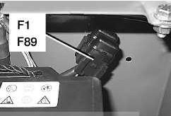
Fuses located in battery compartment

| Function | Number | Ampere ratting [A] |
| Flasher unit Independent heating Onboard radio Alarm Central closing |
F1 | 25 |
| Tachograph (non ADR) | F89 | 5 |
| Tachograph (ADR) | F89 | 1 |
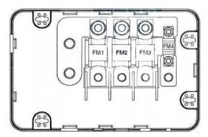
Fuses in fuse box (1) located in battery compartment

| Function | Number | Ampere ratting [A] |
| Cab power supply | FM1 | 125 |
| Electric tail-lift | FM2 | 200 |
| Engine intake air preheating | FM3 | 125 |
| — | FM4 | 40 |
WARNING: Terminal and harness assignments for individual connectors will vary depending on vehicle equipment level, model, and market.
