Smart City Coupe (2002- 2007) – fuse box diagram
Year of production: 2002, 2003, 2004, 2005, 2006, 2007
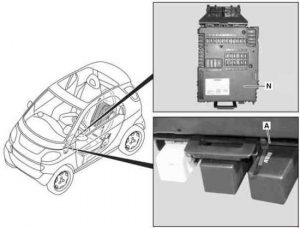
Fuse box – location

N – Fuse Box
A – Relay
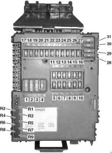
Fuse box

| No. | Fused function | A |
| 1 | Starter | 25 |
| 2 | Windshield wiper, washer pump | 20 |
| 3 | Heater blower Heated seats, only with heated seats |
20 |
| 4 | Left/right power window | 30 |
| 5 | Low beam, high beam, front fog lamp, taillamp, backup lamp | 7,5 |
| 6 | Right standing lamp/taillamp, license plate illumination Right side-marker lamp, only for Canada |
7,5 |
| 7 | Left standing lamp/taillamp, parking lamp Left side-marker lamp, only for Canada |
7,5 |
| 8 | Engine main relay, circuit 87/3 | 20 |
| 9 | Engine main relay, circuit 87/2 | 10 |
| 10 | Engine main relay, circuit 87/1 | 15 |
| 11 | Instrument cluster, safety console, data link connector Horn, only with leather sport steering wheel with steering wheel rocker switch system | 7,5 |
| 12 | Radio CD, interior lamp | 15 |
| 13 | Front fog lamp | 15 |
| 14 | ESP control unit | 25 |
| 15 | Charge air fan motor Air conditioning compressor, only with air conditioning system Plus |
15 |
| 16 | Electric fuel pump | 10 |
| 17 | Rear window wiper (fortwo coupe) | 15 |
| 18 | ESP control unit, restraint systems control unit | 7,5 |
| 19 | Outside mirror adjustment, only with electrically adjustable and heated outside mirrors | 7,5 |
| 20 | Radio, instrument cluster, tachometer, data link connector, backup lamp CD changer | 15 |
| 21 | Interior socket Cigarette lighter, only with smoking set |
15 |
| 22 | Right low beam | 7,5 |
| 23 | Left low beam | 7,5 |
| 24 | Right high beam | 7,5 |
| 25 | Left high beam, high beam indicator lamp | 7,5 |
| 26 | Stop lamps | 15 |
| 27 | MEG engine electronics control unit, EDG engine control unit | 7,5 |
| 28 | Rear window heater (fortwo coupe), cooling fan motor | 30 |
| 29 | Soft top (fortwo cabrio) Electric glass sliding roof (as of model year 2005) |
30 |
| 30 | Electronic selector lever module control unit | 40 |
| 31 | Horn, central locking, remote trunk lid release | 30 |
| R1 | Electric glass sliding roof (up to model year 2004) | 15 |
| R2 | Multifunction control unit, only for Canada | 5 |
| R3 | vacant | — |
| R4 | vacant | — |
| R5 | Multifunction control unit, only for Canada | 15 |
| R6 | vacant | — |
| R7 | vacant | — |
| R8 | Soft top (fortwo cabrio) | 25 |
| R9 | Heated seats | 25 |
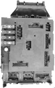
Fuse box (rear)

| No. | Fused function | A |
| 32 | Secondary air injection pump (emission control) | 30 |
| 33 | Ignition switch | 50 |
| 34 | ESP control unit (N47-5) | 50 |
| 35 | Steering assist control unit (N68) | 30 |
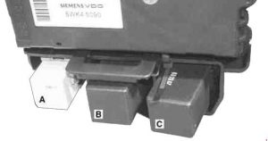
Relay

| No. | Relay |
| A | Fog lamp relay |
| B | Left heated seat control unit |
| C | Right heated seat control unit |
WARNING: Terminal and harness assignments for individual connectors will vary depending on vehicle equipment level, model, and market.
