Smart Fortwo (A450, C450) (1998 – 2002) – fuse box diagram
Year of production: 1998, 1999, 2000, 2001, 2002
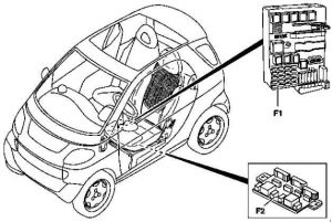
Fuse box – location

- Under the dashboard
- Under the carpet, under the left seat
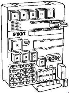
Fuse box under the dashboard

| No. | Fused function | A |
| 1 | Right standing lamp and taillamp, instrument lighting, license plate lamp | 7,5 |
| 2 | Left standing lamp and taillamp | 7,5 |
| 3 | Front fog lamp | 15 |
| 4 | Rear fog lamp | 7,5 |
| 5 | Left low beam with headlamp range adjustment | 7,5 |
| 6 | Right low beam with headlamp range adjustment | 7,5 |
| 7 | Left high beam, high beam indicator | 7,5 |
| 8 | Right high beam | 7,5 |
| 9 | Engine 160 as of 16.11.99: Ignition coil, starter | 25 |
| Engine 660 as of 16.11.99: Starter | 15 | |
| 10 | as of 16.11.99: Turn signal lamps, stop lamps | 15 |
| 11 | Radio, navigation system, CD changer, instrument cluster, tachometer, backup lamp, automatic child seat recognition, diagnostic socket, PTC heater booster switch (engine 660) | 15 |
| 12 | 12 volt socket | 15 |
| 13 | Rear interior lamp, diagnostic socket | 15 |
| 14 | Radio, navigation system, CD changer | 15 |
| 15 | Control modules: instrument cluster, ZEE, central locking, anti-theft alarm system, trunk lid remote unlocking, front interior lamp | 7,5 |
| 16 | Central locking, safety console, clock, horn, trunk lid remote unlocking, interior lamp | 15 |
| 17 | Rear window wiper motor | 15 |
| Cabrio: Heated seats | 25 | |
| 18 | Heated seats Cabrio: Soft top motor |
25 |
| 19 | Cabrio: Soft top motor | 25 |
| Glass sliding roof | 15 | |
| 20 | Engine 160: Engine control module | 7,5 |
| 21 | Rear window heater, engine fan | 30 |
| 22 | as of 16.11.99: Gearshift system, circuit 30 relay box | 40 |
| up to 15.11.99: Turn signal lamps, stop lamps | 15 | |
| 23 | Heater fan | 20 |
| 24 | Left and right power windows | 30 |
| 25 | Front wiper, washer pump, rear wiper | 20 |
| 26 | Control modules: ABS, airbag, ZEE | 7,5 |
| 27 | ABS | 50 |
| Relay | ||
| A | Fog lamp relay | |
| B | up to 15.11.99: CL opening relay as of 16.11.99: Remote trunk opening relay |
|
| C | up to 15.11.99: CL closing relay as of 16.11.99: Rear wiper intermittent wipe relay |
|
| D | Horn relay | |
| E | up to 15.11.99: Remote trunk opening relay as of 16.11.99: Heater blower, power window and relief relay |
|
| F | Heated rear window relay | |
| G | Engine fan relay | |
| H | Left turn signal indicator relay | |
| I | Right turn signal indicator relay | |
| K | up to 15.11.99: Heater blower, power window and relief relay as of 16.11.99: Front wiper intermittent wipe relay |
|
| L | Headlamp relay | |
| M | Headlamp relay | |
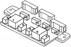
Fuse box under the carpet, under the left seat

| No. | Fused function | A |
| S1 | Charge air cooler, refrigerant compressor magnetic clutch | 15 |
| S2 | Fuel pump | 10 |
| S3 | Engine 160: Injection valves, MEG Engine 660: Injectors, electrical cut-off, pressure valve |
15 |
| S4 | Engine 160: Tank vent valve, oxygen sensor Engine 660: Glow time control |
10 |
| Relay |
||
| P | Electric fuel pump relay |
|
| Q | Automated manual transmission relay | |
| R | Main relay | |
| S | Charge air cooler fan relay | |
| T | Starter relay | |
| U | Air conditioner compressor magnetic clutch relay | |
WARNING: Terminal and harness assignments for individual connectors will vary depending on vehicle equipment level, model, and market.
