Subaru Outback (2020 – 2021) – fuse and relay box diagram
Year of production: 2020, 2021
This article examines the seventh‑generation Subaru Legacy and the sixth‑generation Subaru Outback, produced from 2020 onward. You’ll find fuse box diagrams for the 2020 and 2021 models, guidance on locating the fuse panels within the vehicle, and a detailed overview of each fuse’s function and layout.
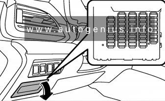
Passenger compartment fuse box
Fuse Box Location
It is located behind the cover below and to the left of the steering wheel.
Fuse Box Diagram
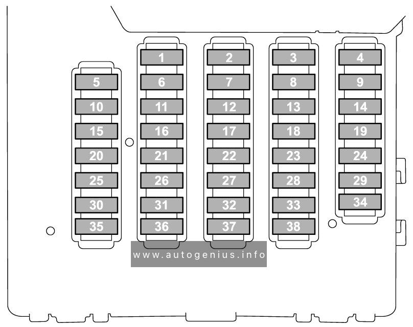
Assignment of fuses in the instrument panel (2020-2021)
| Fuse | Ampere rating [A] | Circuit |
| 1 | – | Not Used |
| 2 | 20 A | CIGAR |
| 3 | 7.5 A | IG A-1 |
| 4 | 15 A | AUDIO NAVI |
| 5 | 10 A | IG B-2 |
| 6 | 7.5 A | METER IG (DCDC) |
| 7 | 20 A | 12V SOCKET |
| 8 | 10 A | A/C IG |
| 9 | 7.5 A | ACC |
| 10 | 7.5 A | IG B-1 |
| 11 | 7.5 A | EYE SIGHT (DCDC) |
| 12 | – | Not Used |
| 13 | 7.5 A | IG A-3 |
| 14 | – | Not Used |
| 15 | – | Not Used |
| 16 | 7.5 A | UNIT IG (DCDC) |
| 17 | 7.5 A | MIRROR ACC |
| 18 | – | Not Used |
| 19 | 10 A | IG A-2 |
| 20 | 10 A | SRS AIRBAG |
| 21 | 7.5 A | A/C IG (DCDC) |
| 22 | 10 A | EYE SIGHT |
| 23 | 7.5 A | IGA-4 |
| 24 | 7.5 A | A/C ACC (DCDC) |
| 25 | 7.5 A | UNIT +B (DCDC) |
| 26 | 10 A | BACK UP |
| 27 | 15 A | SEAT HTR R |
| 28 | 20 A | TRAIL R.FOG |
| 29 | – | Not Used |
| 30 | 7.5 A | BACK UP (DCDC) |
| 31 | 7.5 A | SMT (DCDC) |
| 32 | 15 A | MIRROR +B |
| 33 | 7.5 A | KEY SW A |
| 34 | – | Not Used |
| 35 | 7.5 A | ILLUMI (DCDC) |
| 36 | 7.5 A | KEY SW B |
| 37 | 15 A | UNIT +B1 |
| 38 | 7.5 A | UNIT +B2 |
Engine compartment fuse box
Fuse Box Diagram

Assignment of fuses in the engine compartment (2020-2021)
| Fuse | Ampere rating [A] | Power consumer |
| 1 | – | Not Used |
| 2 | 7.5 A | OBD |
| 3 | 7.5 A | STOP |
| 4 | 10 A | MB-B |
| 5 | 7.5 A | PU B/UP |
| 6 | 30 A | JB-B2 |
| 7 | 7.5 A | M/B-IG1 |
| 8 | 7.5 A | M/B-IG2 |
| 9 | 10 A | M/B-IG3 |
| 10 | 7.5 A | M/B-IG4 |
| 11 | 7.5 A | HORN1 |
| 12 | 7.5 A | HORN2 |
| 13 | 10 A | TAIL |
| 14 | 15 A | HAZARD |
| 15 | 20 A | D/L |
| 16 | 20 A | F/P |
| 17 | – | Not Used |
| 18 | – | Not Used |
| 19 | 10 A | AVCS |
| 20 | 15 A | ETC |
| 21 | 15 A | TCU |
| 22 | 7.5 A | CVT SSR |
| 23 | 10 A | E/G2 |
| 24 | 15 A | IG COIL |
| 25 | 20 A | O2 HTR |
| 26 | 20 A | DI |
| 27 | 15 A | E/G1 |
| 28 | 25 A | MAIN FAN |
| 29 | 15 A | DEICER |
| 30 | 30 A | VDC SOL |
| 31 | 15 A | F-END |
| 32 | 30 A | F.WIP |
| 33 | 25 A | R.DEF |
| 34 | 30 A | BACKUP |
| 35 | 20 A | HTR |
| 36 | 25 A | SUB FAN |
| 37 | 15 A | R.WIP |
| 38 | 20 A | BLOWER |
| 39 | 20 A | BLOWER |
| 40 | 10 A | MB-A |
| 41 | – | Not Used |
| 37 | 15 | BLOWER |
| 38 | 10 | F.FOG RH |
| 39 | 10 | F.FOG LH |
| 40 | — | — |
| 41 | 15 | STRG/H |
| Spare fuses are located on the fusebox cover. | ||
WARNING: Terminal and harness assignments for individual connectors will vary depending on vehicle equipment level, model, and market.