Suzuki Swift (2004 – 2010) – fuse box diagram
Year of production: 2004, 2005, 2006, 2007, 2008, 2009, 2010
Fuses in the Engine Compartment (Petrol)
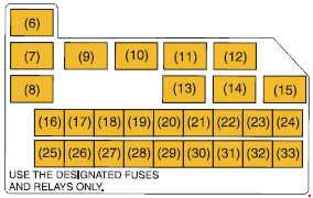
 Suzuki Swift – fuse box diagram – engine compartment (patrol)

 Suzuki Swift – fuse box diagram – engine compartment (patrol)
No.
|
A
|
Function/component
|
| 1 |
80 |
All electric load |
| 2 |
50 |
Power window, Ignition, Wiper, Starter |
| 3 |
50 |
Tail light, Rear defogger, Door lock, Hazard/Horn, Dome |
| 4 |
80 |
Heater, Air compressor, Power steering |
| 5 |
80 |
Radiator fan, Front fog light, Head light |
| 16 |
30 |
Heater |
| 17 |
15 |
FI |
| 18 |
10 |
Air compressor |
| 19 |
– |
Not used |
| 20 |
15 |
Brake light switch |
| 21 |
30 |
ABS control module |
| 22 |
30 |
Starting motor |
| 23 |
|
Not used |
| 24 |
50 |
Power steering control module |
| 25 |
30 |
Ignition switch |
| 26 |
30 |
Radiator fan |
| 27 |
– |
Not used |
| 28 |
30 |
ABS control module |
| 29 |
– |
Not used |
| 30 |
– |
Not used |
| 31 |
15 |
Front fog light |
| 32 |
15 |
Headlight (Left) |
| 33 |
15 |
Headlight (Right) |
| Relay |
| 6 |
Radiator fan relay #1 |
| 7 |
Radiator fan relay #2 |
| 8 |
Radiator fan relay #3 |
| 9 |
Starting motor relay |
| 10 |
Main relay |
| 11 |
Not used |
| 12 |
Front fog light relay |
| 13 |
Fuel pump relay |
| 14 |
Air compressor relay |
| 15 |
Not used |
Fuses in the Engine Compartment (Diesel)
 Suzuki Swift – fuse box diagram – engine compartment (diesel)
 Suzuki Swift – fuse box diagram – engine compartment (diesel)
 Suzuki Swift – fuse box diagram – engine compartment (diesel)
No.
|
A
|
Function/component
|
| 1 |
30 |
A Starting motor |
| 2 |
10 |
Air compressor |
| 3 |
15 |
Fuel pump |
| 4 |
30 |
FI |
| 5 |
30 |
Heater |
| 6 |
30 |
Radiator fan |
| 7 |
50 |
Power steering control module |
| 13 |
30 |
ABS control module |
| 14 |
30 |
ABS control module |
| 15 |
15 |
Brake light switch |
| 16 |
15 |
Headlight (Right) |
| 17 |
15 |
Headlight (Left) |
| 18 |
15 |
Front fog light |
| 19 |
30 |
Ignition switch |
| 20 |
50 |
Power window, Ignition, Wiper, Starter |
| 21 |
100 |
Main |
| 22 |
100 |
EPS, A/C, Fuel pump, IG1 |
| 23 |
100 |
Lamps, ABS, ACC, IG2 |
| 24 |
50 |
Junction box |
| 25 |
80 |
Glow controller |
| 29 |
20 |
F.l. |
| 30 |
20 |
ECU (if equipped) |
| 31 |
10 |
ECU, EGR |
| Relay |
| 8 |
Radiator fan relay #1 |
| 9 |
Radiator fan relay #2 |
| 10 |
Radiator fan relay #3 |
| 11 |
Air compressor relay |
| 12 |
Starting motor relay |
| 26 |
Fog Lamp relay |
| 27 |
Fuel pump relay |
| 28 |
F.l. main relay |
Fuses under the Dash Board
 Suzuki Swift – fuse box diagram – dashboard
No.
|
A
|
Function/component
|
| 1 |
– |
Not used |
| 2 |
15 |
Ignition coil |
| 3 |
10 |
Back-up light |
| 4 |
10 |
Meter |
| 5 |
15 |
Cigar |
| 6 |
15 |
Accessory |
| 7 |
30 |
Power window |
| 8 |
15 |
Wiper / Washer |
| 9 |
10 |
Power steering / IG1 Signal |
| 10 |
15 |
Air bag |
| 11 |
10 |
Anti-lock brake system |
| 12 |
10 |
Tail light |
| 13 |
– |
Not used |
| 14 |
20 |
Door lock |
| 15 |
10 |
Immobilizer (Diesel Engine) |
| 16 |
10 |
Starting motor |
| 17 |
– |
Not used |
| 18 |
10 |
Heater / IG2 Signal |
| 19 |
15 |
RR fog lamp |
| 20 |
15 |
Radio / Dome |
| 21 |
20 |
Rear defogger |
| 22 |
15 |
Horn / Hazard |
| 23 |
– |
Not used |
| 24 |
– |
Not used |
WARNING: Terminal and harness assignments for individual connectors will vary depending on vehicle equipment level, model, and market.
