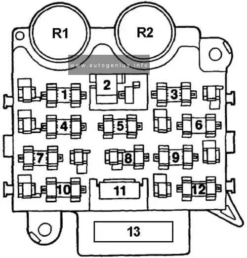
Year of production: 1988, 1989, 1990, 1991, 1992, 1992, 1993, 1994, 1995, 1996, 1997
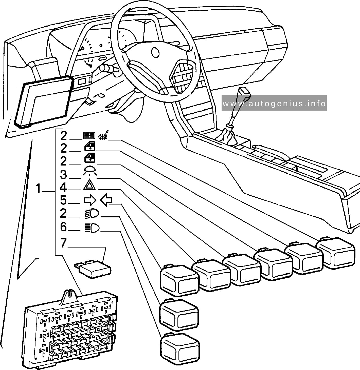
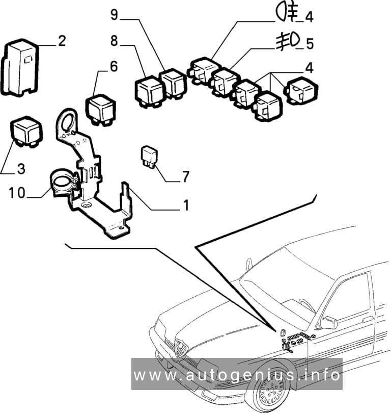
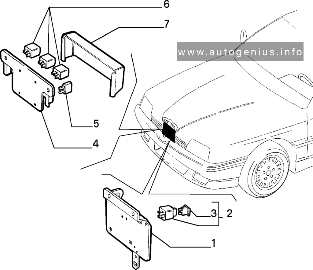
Alfa Romeo 164 is a business class car manufactured by Alfa Romeo. Produced from 1987 to 1998 in the sedan body. This material is suitable for cars produced in 1988, 1989, 1990, 1991, 1992, 1993, 1994, 1995, 1996, 1997 for finding and replacing fuses and relays on Alfa Romeo 164 cars. We will also show the fuse box diagrams and their locations, as well as the purpose of their elements.
Year of production: 19991, 1992, 1993, 1994, 1995, 1996, 1997
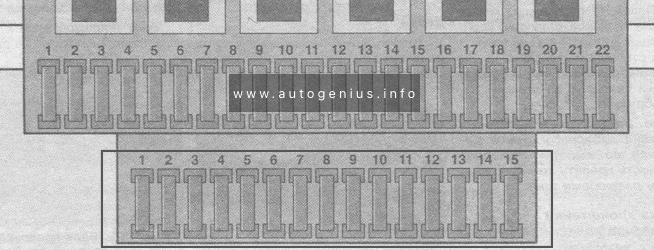
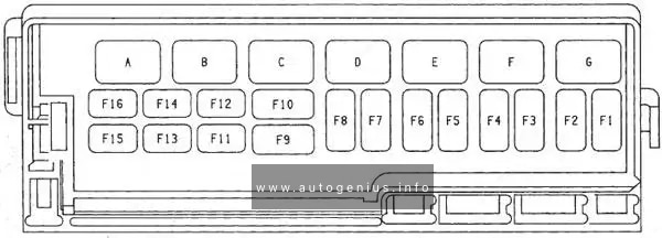
The 3rd generation Volkswagen Golf compact car was produced in 1991, 1992, 1993, 1994, 1995, 1996, 1997, 1998, 1999, 2000, 2001 and 2002 with gasoline and diesel engines. Delivered worldwide in various body styles: convertible, sedan, station wagon and hatchback. In this article you will find a designation of the fuse and relay boxes diagram of the 3rd generation Volkswagen Golf.
Passenger compartment
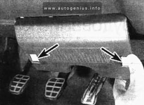
Fuse box location
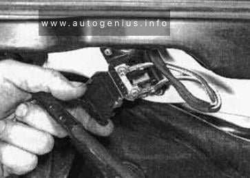
It is located at the bottom of the dashboard on the driver’s side, behind the protective cover. To remove it, press the buttons – latches.
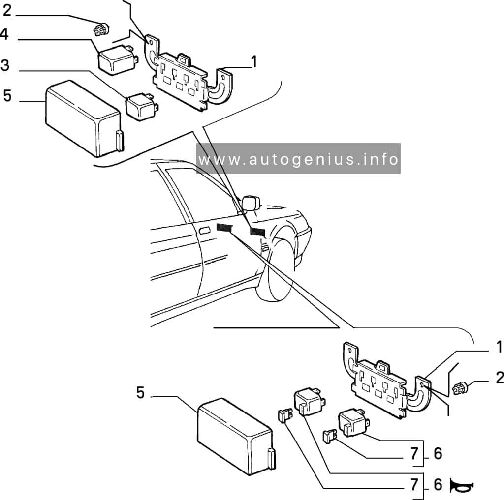
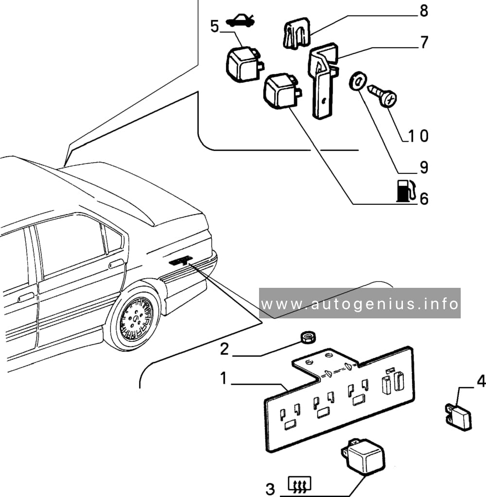
Year of production: 1990, 1991, 1992, 1993, 1994, 1995, 1996, 1997, 1998, 1999, 2000, 2001, 2002, 2003
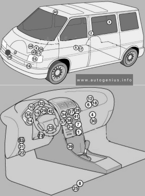
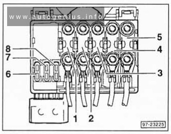
Volkswagen Transporter T4 – represents the 4th generation of the legendary Transporter series. This model was produced in 1990, 1991, 1992, 1993, 1994, 1995, 1996, 1997, 1998, 1999, 2000, 2001, 2002 and 2003 with diesel and gasoline engines with different wheelbases: short and long, and with different roof height. Also on the T4, Volkswagen continued its lineup of luxury Caravelle, California and Multivan models. In this article, we will show the location of all electronic control sides and a detailed designation of the purpose of fuses and relays Volkswagen T4 with box diagrams in which they are located.
Air conditioning control unit 1 – with automatic temperature control – in the heater control panel, front
2
Air conditioning control unit 2 – with automatic temperature control – in the heater control panel, rear – central pillar
3
Evaporator Fan Control Unit (A / C) – With Rear A / C – Behind Right Rear Trim Panel
4
Air conditioning / heater fan motor control unit 1 – with automatic temperature control – front – fan unit
5
Air conditioning / heater blower motor control unit 2- with automatic temperature control – rear- bottom of the body, in the center
6
Aerial amplifier – behind the dash, passenger side
7
Alternator resistor – near additional relays – CV / AUF, with alternator 150A / automatic transmission / automatic temperature control – behind the central part of the dashboard
8
Additional battery – under the driver’s seat
9
Accumulator battery
10
Central locking signal control unit – behind the dashboard
11
Cruise control unit (with throttle motor) – cruise control is controlled by the ECM
12
Electronic cruise control module (without throttle motor) – behind dash, passenger side
13
Diagnostic connector (DLC) – instrument panel, driver’s side
14
Diagnostic unit – 05/99 (except for AAC / ABL / AET / AES / AJA) – in the instrument cluster
15
Cooling Fan Motor Relay – Behind Left Headlight
16
Cooling Fan Motor 1/2 Resistor – Behind Left Headlight
17
Coolant heater control unit (with additional coolant heater – D3W / B4W / D4W) – in the heater – underbody, in the center
18
Coolant heater control unit (with optional coolant heater – B7W / D7W) – behind the dash, passenger side
19
Engine oil pressure warning buzzer – in instrument cluster control unit
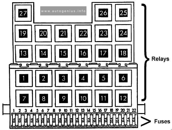
Windshield wiper / washer, heaters for windshield washer nozzles (05/01)
6
30
Air conditioning system, heater fan motor
7
10
Front right side / rear right side lamps
8
10
Lamps front left / rear left
9
20
Heated rear window, heated outside mirror
10
15
Fog lights
11
10
Left headlamp-high beam
12
10
RH headlamp-high beam
13
10
Sound signal
14
10
ABS system (with ESP), automatic transmission control system, additional equipment, central locking, cruise control system, power windows, power rear-view mirrors on the doors, reverse light (s)
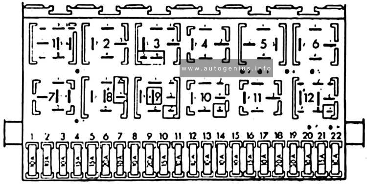
Heater blower motor relay – automatic temperature control
5
(152)
Heater radiator coolant valve relay (rear heater)
6
(38)
Air intake changeover actuator relay (A / C / heater)
7
(53)
Alternator relay (AES, with 150A alternator)
8
(53)
Alternator relay (ACV / AUF, with alternator 150A / automatic / automatic temperature control)
9
(175)
Start inhibit switch relay / reversing lamp relay
10
(87)
Wheel hub connection control unit
Another unit can be located under the driver’s seat. The following items may be located there: (214/426) Relay for additional battery, (403) Relay for additional heater, (30A) Additional liquid heating system, (5A) Sockets , etc.
Engine compartment
Fuse box location
This unit is located on the cover in front of the battery.
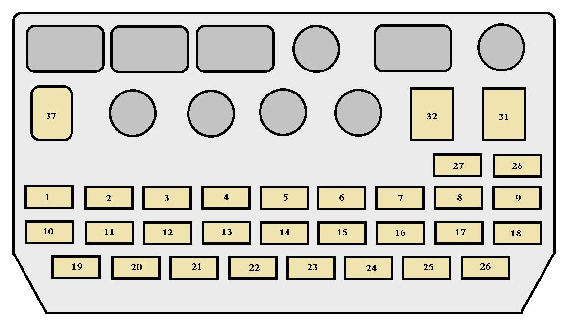
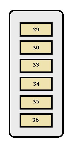
Year of production: 1987, 1988, 1989, 1990, 1991, 1992, 1993, 1994, 1995, 1995
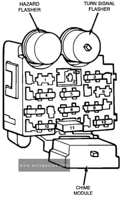
This article focuses on the first-generation Jeep Wrangler (YJ), manufactured between 1987 and 1995. It includes fuse box diagrams for the 1987–1995 models, details the locations of the fuse panels within the vehicle, and provides information on the function and layout of each fuse and relay.
Interior lights, luggage compartment light, clock, open door warning light, radio, cassette tape player, Compact Disc player
15
DEFOG
15
Rear window defogger
16
ECU-B
15
Anti-lock brake system, electronically controlled automatic transmission system
17
CIG
15
Cigarette lighter, digital clock display, power rear view mirrors, theft deterrent system, SRS airbag system, automatic transmission shift lock system
18
EFI
15
Multiport fuel injection system/sequential multiport fuel injection system
19
TURN
7,5
Turn signal lights
20
GAUGE
10
Gauges and meters, service reminder indicators and warning buzzers (except discharge and open door warning lights), back-up lights, automatic transmission overdrive system, rear window defogger, electric rear sun roof, power windows, power door lock system
21
FR-WIPER
30
Windshield wipers and washer
22
ENGINE OIL
15
Engine oil autofeed system
23
RR-WIPER
15
Rear window wiper and washer
24
A/C
15
Air conditioning cooling system, cool box
25
ECU-IG
15
Cruise control system, electronically controlled automatic transmission system, anti-lock brake system, theft deterrent system
26
FR-W ASHER
10
Windshield washer motor
27
HEAD (LH-UPR)
10
Left-hand headlight (Canada only)
28
HEAD (RH-UPR)
10
Right-hand headlight (Canada only)
29
ALT-S
7,5
Charging system
30
AM2
20
Charging system, discharge warning light, emission control system, multiport fuel injection system/ sequential multiport fuel injection system
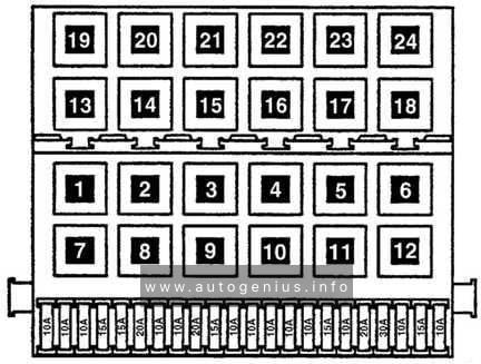
Fuses (type B)
Fuse
Ampere rating [A]
Circuit
31
DOOR
30
Power door lock system, theft deterrent system
32
POWER
30
Electric rear sun roof, power windows
Fuses (type C)
Fuse
Ampere rating [A]
Circuit
33
ABS
60
Anti-lock brake system
34
ALT
100
“ABS”, “AM1”, “STOP”, “DEFOG”, “FOG”, “ECU-B”, “TAIL”, “A/C” and “RR A/C” fuses, and “FR-HTR” circuit breaker