Year of production: 1992, 1993, 1994, 1995, 1996, 1997, 1998, 1999
The Volkswagen Vento A3, (the third generation of the Volkswagen Vento), was a compact family car produced from 1992 to 1999. In this article, you will find fuse box diagrams for Volkswagen Vento models from 1992 to 1999, along with details on the fuse panel locations inside the vehicle and the specific functions of each fuse (fuse layout) and relay.
Passenger compartment
Fuse Box Location
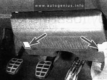
It is located under the dashboard on the driver’s side. Press down on the latches and remove the cover to access the fuses.
Year of production: 1992, 1993, 1994, 1995, 1996, 1997, 1998, 1999
The Volkswagen Jetta A3, (the third generation of the Volkswagen Jetta), was a compact family car produced from 1992 to 1999. In this article, you will find fuse box diagrams for Volkswagen Jetta models from 1992 to 1999, along with details on the fuse panel locations inside the vehicle and the specific functions of each fuse (fuse layout) and relay.
Passenger compartment
Fuse Box Location
It is located under the dashboard on the driver’s side. Press down on the latches and remove the cover to access the fuses.
Jeep Grand Cherokee ZJ/ZG (1993 – 1995) – fuse and relay box diagram
Year of production: 1993, 1994, 1995
This article focuses on the post-facelift first-generation Jeep Grand Cherokee (ZJ), manufactured between 1996 and 1998. It provides fuse box diagrams for the 1996, 1997, and 1998 models, details the locations of the fuse panels within the vehicle, and explains the purpose of each fuse (fuse layout) and relay.
Passenger compartment fuse box
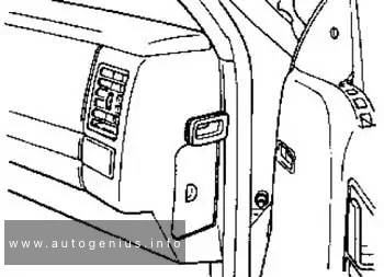
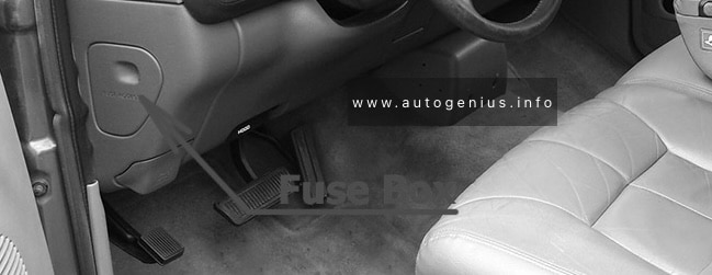
Fuse Box Location
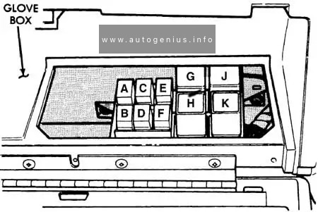
Jeep Grand Cherokee ZJ/ ZG (1993 – 1995) – fuse and relay box location – passenger compartment
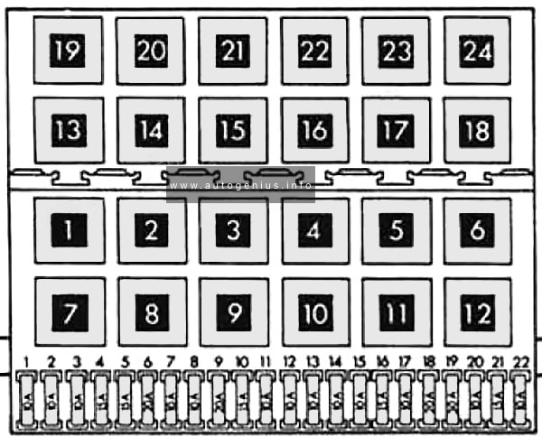
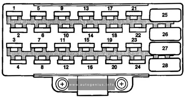
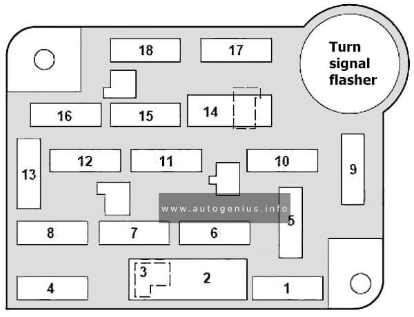
Fuse Box Diagram
Jeep Grand Cherokee ZJ/ ZG (1993 – 1995) – fuse and relay box diagram – passenger compartment
Assignment of the fuses and relay under the dashboard
Overhead Console, Keyless Entry Module, Radio Memory, Clock/Chime Module, Power Locks, Power Mirrors, Heating Ventilation Air Conditioning (HEVAC) Module, Convenience Control Module, Vehicle Info Center (VIC)
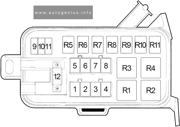
The Dodge Ram 3500 (1994–1997) is a heavy-duty truck from Dodge’s second generation of Ram pickups, renowned for its strength, durability, and impressive towing and payload capacity. The 1994 redesign marked a revolutionary shift for Dodge, with the introduction of the iconic big-rig-inspired design and a focus on making the Ram 3500 a go-to vehicle for those in need of serious power. This generation of the Ram 3500 was popular among contractors, farmers, and others needing a truck that could handle the most demanding tasks.
Passenger Compartment Fuse Box
Fuse Box Location
The fuse panel is located behind the cover on the driver’s side of the instrument panel.
Ignition Off Draw, Clock Memory, Underhood Lamp, Power Mirror Switch, Time Delay Relay, Buzzer Module, Data Link Connector, Radio Choke Relay, Glove Box Lamp Switch, Radio
18
15
’94-’95: Parking Lamps
15
’96-’97: Headlamp Switch, Radio, Overhead Console, Fog Lamp Relay
The Dodge Ram 2500 (1994–1997) was part of the second generation of Dodge Ram trucks, which saw a complete redesign in 1994. This generation brought Dodge back into the spotlight in the truck market due to its bold new styling and heavy-duty performance. The Ram 2500 was positioned between the lighter-duty Ram 1500 and the heavy-duty Ram 3500, making it a popular choice for buyers who needed a capable work truck with substantial towing and payload capacity.
Passenger Compartment Fuse Box
Fuse Box Location
The fuse panel is located behind the cover on the driver’s side of the instrument panel.
Ignition Off Draw, Clock Memory, Underhood Lamp, Power Mirror Switch, Time Delay Relay, Buzzer Module, Data Link Connector, Radio Choke Relay, Glove Box Lamp Switch, Radio
18
15
’94-’95: Parking Lamps
15
’96-’97: Headlamp Switch, Radio, Overhead Console, Fog Lamp Relay
Year of production: 1994, 1995, 1996, 1997, 1998, 1999
The Dodge Neon was a compact car produced by Chrysler Corporation under the Dodge brand, from 1994 to 2005. Known for its affordability, sporty handling, and peppy performance, it was one of the more exciting economy cars of its era.
First Generation (1994–1999), Second Generation (2000–2005), Dodge Neon SRT-4 (2003–2005)
Passenger Compartment Fuse Box
Fuse box location
The fuse panel is located behind the cover on the driver’s side of the dashboard.
Dome Lamp, Trunk Lamp, Underhood Lamp, Instrument Cluster, Radio, Glove Box Lamp, Map/Reading Lamp, Visor/Vanity Lamp, Power Mirror Switch, High Speed Warning Module (’98-’99), Time Delay Relay (’98-’99), Time Out Relay (’98-’99)
16
20
Fog Lamp Relay, Rear Fog Lamp Switch
18
10
’95-’97: Air Conditioner Compressor Clutch Relay
20
’98-’99: Air Conditioner Compressor Clutch Relay, ABS
20
10
Turn Signal/Hazard
21
20
Fuel Pump Relay, Auto Shut Down Relay (Fuel Injectors, Ignition Coil Pack, Powertrain Control Module, Generator, Data Link Connector, Oxygen Sensors, Capacitor, Noise Suppressor)
23
15
Horn Relay
25
15
Stop Lamp Switch
Relay
R1
–
R2
Fuel Pump
R3
Auto Shut Down
R4
Horn
R5
Fog Lamp
R6
ABS Warning Lamp
R7
Air Conditioner Compressor Clutch
R8
Starter
WARNING: Terminal and harness assignments for individual connectors will vary depending on vehicle equipment level, model, and market.
Year of production: 1988, 1989, 1990, 1991, 1992, 1992, 1993, 1994, 1995, 1996, 1997
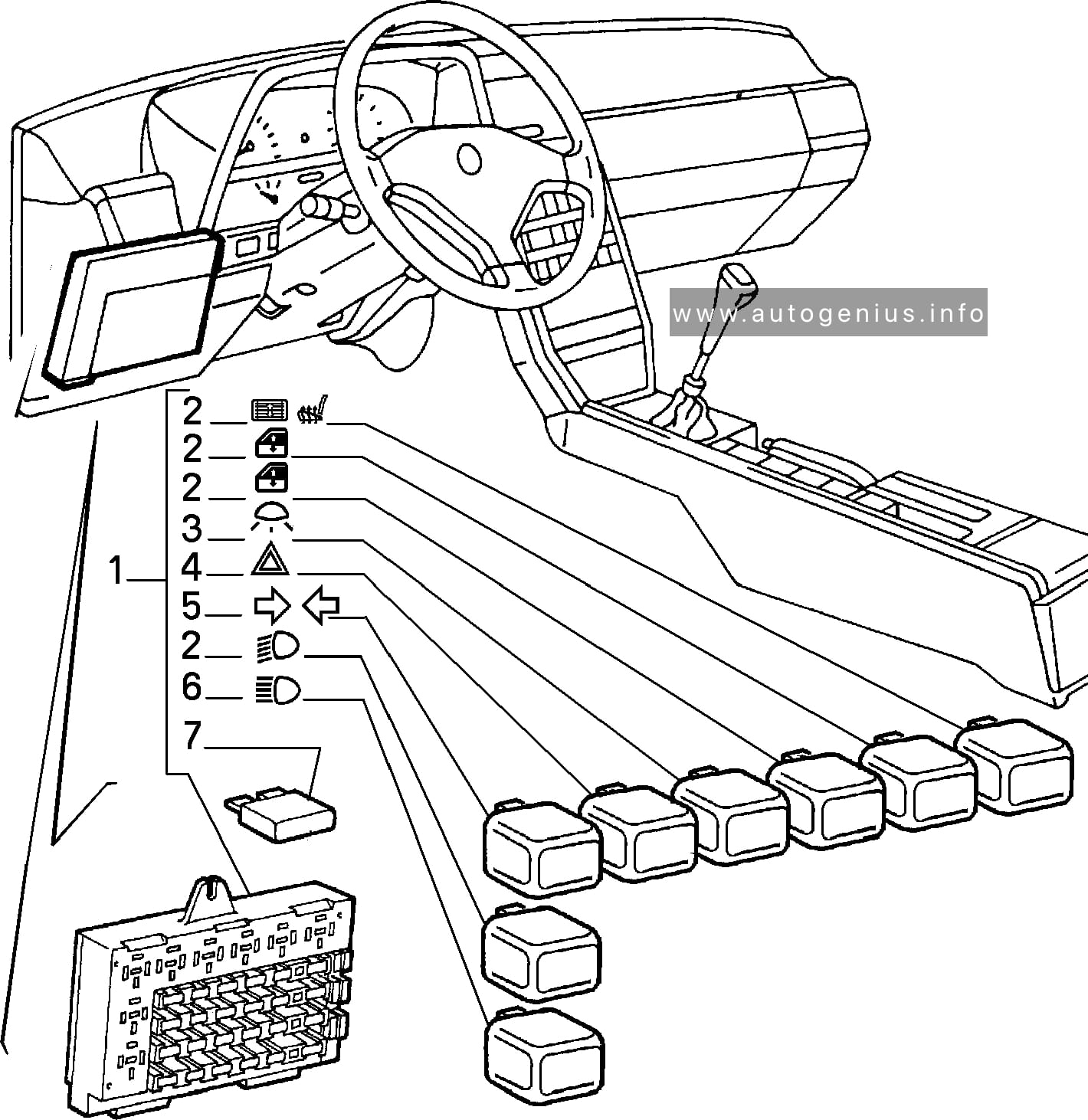
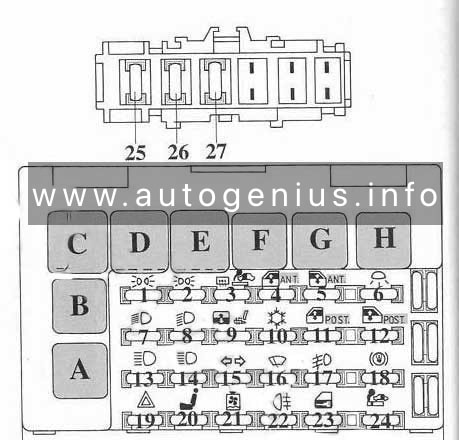
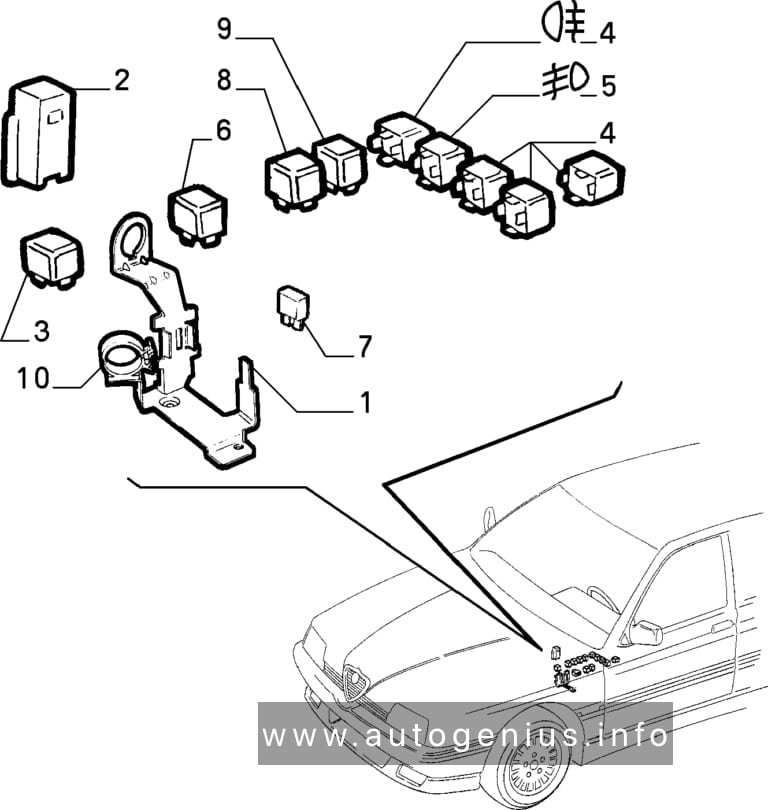
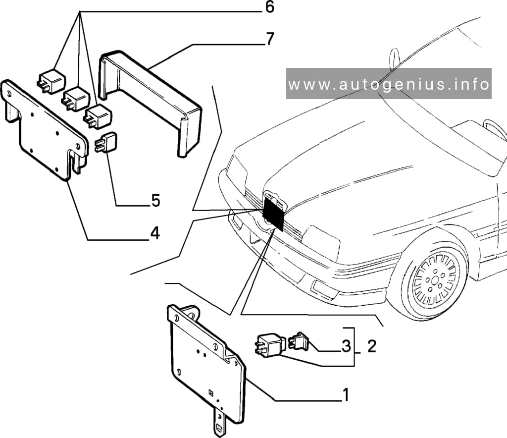
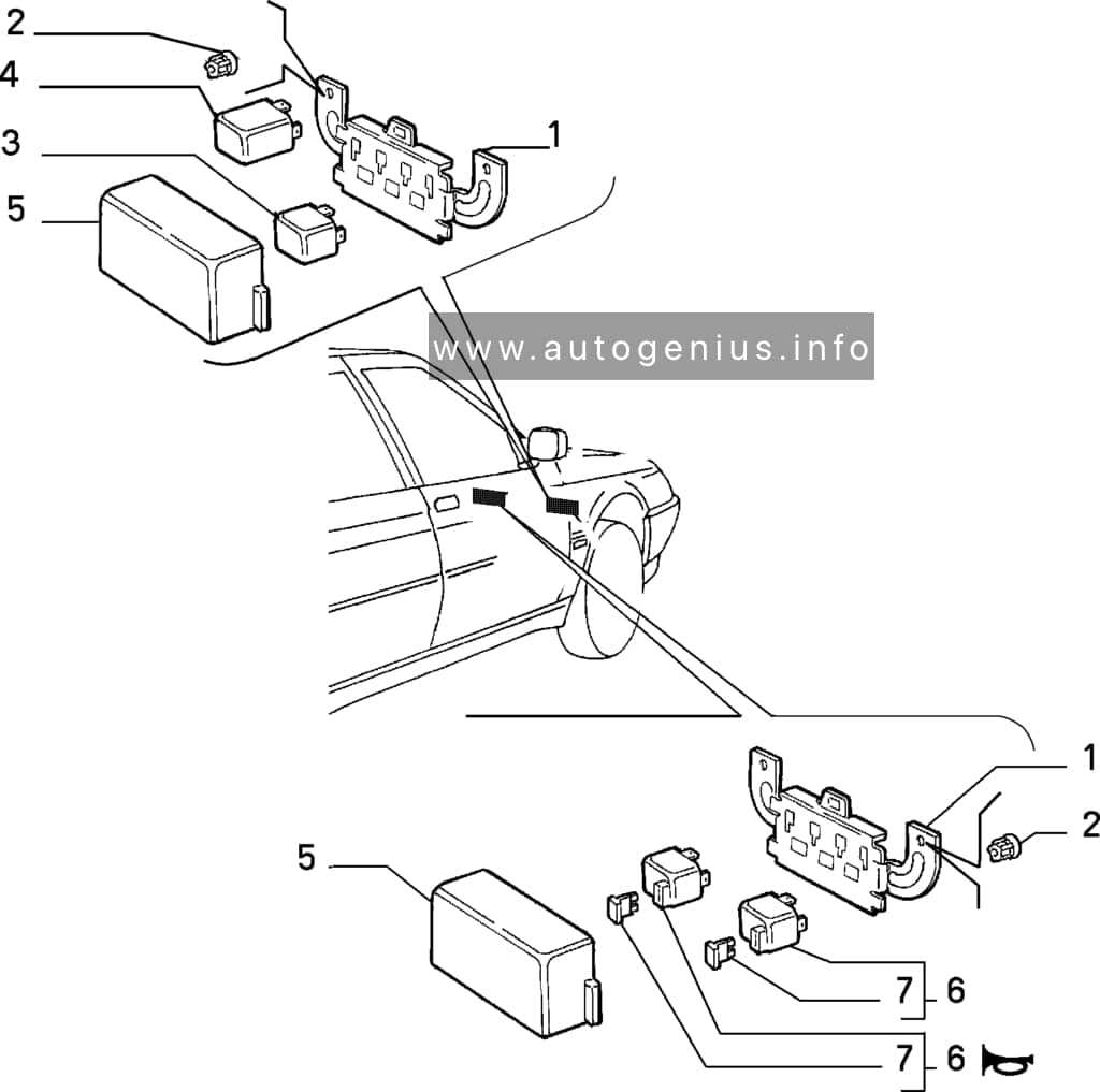
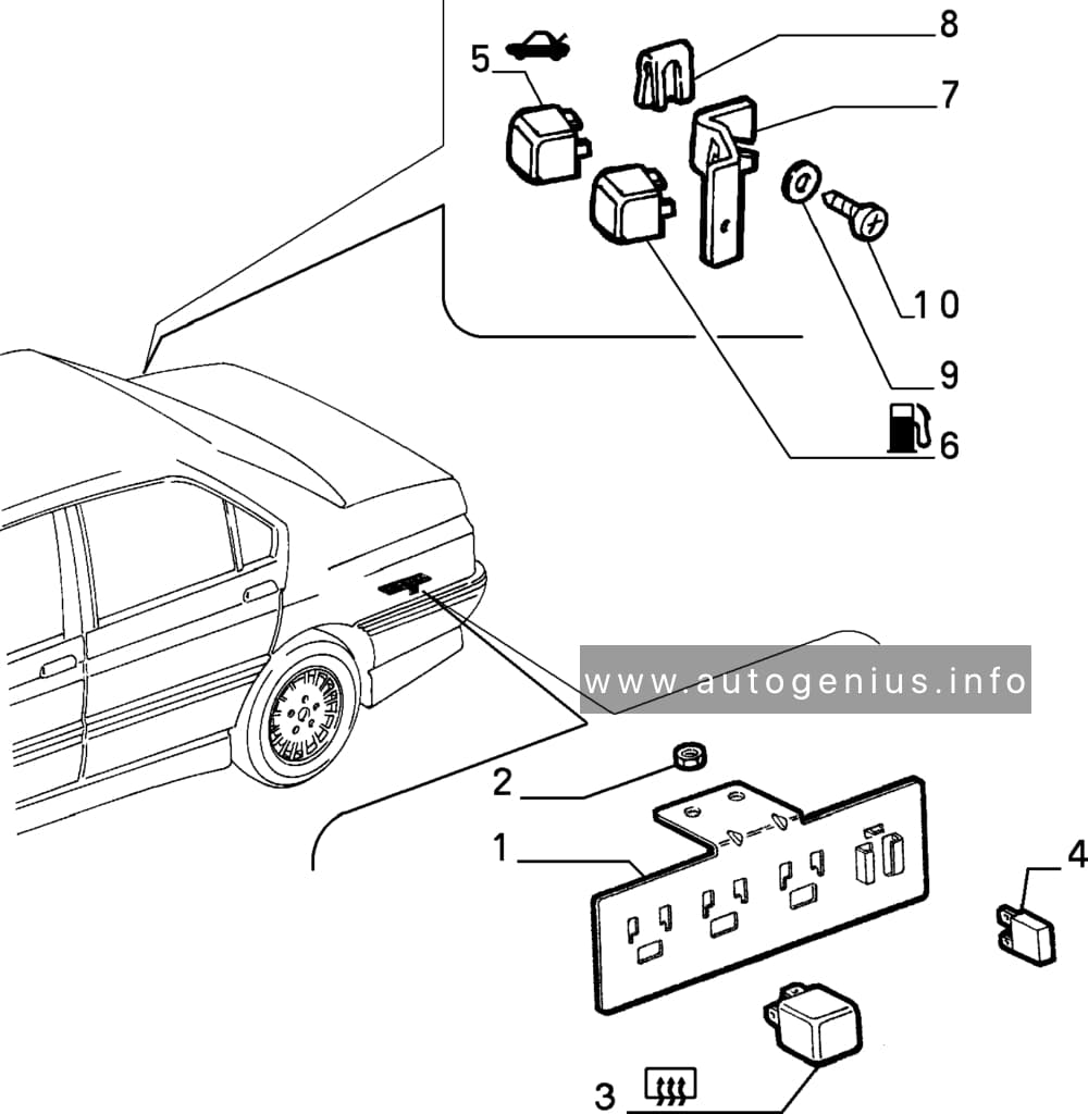
Alfa Romeo 164 is a business class car manufactured by Alfa Romeo. Produced from 1987 to 1998 in the sedan body. This material is suitable for cars produced in 1988, 1989, 1990, 1991, 1992, 1993, 1994, 1995, 1996, 1997 for finding and replacing fuses and relays on Alfa Romeo 164 cars. We will also show the fuse box diagrams and their locations, as well as the purpose of their elements.
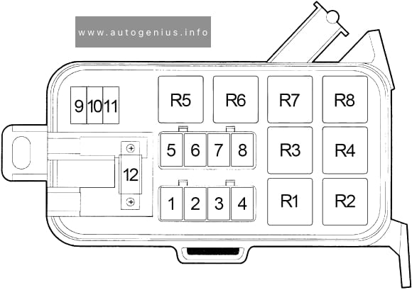
The Dodge Ram 1500 from 1994 to 1997 was a key model in the history of Dodge trucks, marking the debut of the second generation of the Dodge Ram series. This generation saw a radical redesign that helped revitalize Dodge’s truck sales, making the Ram one of the most iconic pickup trucks of the 1990s.
Passenger Compartment Fuse Box
Fuse Box Location
The fuse panel is located behind the cover on the driver’s side of the instrument panel.
Ignition Off Draw, Clock Memory, Underhood Lamp, Power Mirror Switch, Time Delay Relay, Buzzer Module, Data Link Connector, Radio Choke Relay, Glove Box Lamp Switch, Radio
18
15
’94-’95: Parking Lamps
15
’96-’97: Headlamp Switch, Radio, Overhead Console, Fog Lamp Relay
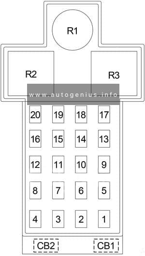
Chrysler Neon (1994 – 1999) – fuse and relay box diagram
Year of production: 1994, 1995, 1996, 1997, 1998, 1999
The Chrysler Neon, also known as the Dodge Neon in some markets, was a compact car produced by Chrysler Corporation from 1994 to 2005. It was initially marketed under both the Dodge and Plymouth brands in North America and as the Chrysler Neon in international markets.
First Generation (1994–1999), Second Generation (2000–2005), Dodge Neon SRT-4 (2003–2005)
Passenger Compartment Fuse Box
Fuse box location
The fuse panel is located behind the cover on the driver’s side of the dashboard.
Chrysler Neon (1994 – 1999) – fuse and relay location – passenger compartment
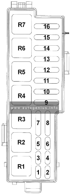
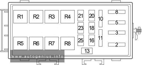
Fuse box Diagram
Chrysler Neon (1994 – 1999) – fuse and relay diagram – passenger compartment
Assignment of fuses in the passenger compartment
No.
A
Circuit Protected
1
15
Cigar Lighter/Power Outlet
2
15
Headlamp Switch (Park Lamp, Tail Lamp, License Lamp, Radio, Front Fog Lamp Switch, Remote Keyless Entry Module (’98-’99))
3
20
Door Lock Switch, Remote Keyless Entry Module (’98-’99), Immobilizer (’98-’99)
Dome Lamp, Trunk Lamp, Underhood Lamp, Instrument Cluster, Radio, Glove Box Lamp, Map/Reading Lamp, Visor/Vanity Lamp, Power Mirror Switch, High Speed Warning Module (’98-’99), Time Delay Relay (’98-’99), Time Out Relay (’98-’99)
16
20
Fog Lamp Relay, Rear Fog Lamp Switch
18
10
’95-’97: Air Conditioner Compressor Clutch Relay
20
’98-’99: Air Conditioner Compressor Clutch Relay, ABS
20
10
Turn Signal/Hazard
21
20
Fuel Pump Relay, Auto Shut Down Relay (Fuel Injectors, Ignition Coil Pack, Powertrain Control Module, Generator, Data Link Connector, Oxygen Sensors, Capacitor, Noise Suppressor)
23
15
Horn Relay
25
15
Stop Lamp Switch
Relay
R1
–
R2
Fuel Pump
R3
Auto Shut Down
R4
Horn
R5
Fog Lamp
R6
ABS Warning Lamp
R7
Air Conditioner Compressor Clutch
R8
Starter
WARNING: Terminal and harness assignments for individual connectors will vary depending on vehicle equipment level, model, and market.
Ford F-150 (1992 – 1997) – fuse and relay box diagram
Year of production: 1992, 1993, 1993, 1994, 1995, 1996, 1997
This article focuses on the ninth-generation Ford F-Series, produced from 1992 to 1997. It provides fuse box diagrams for the 1992, 1993, 1994, 1995, 1996, and 1997 Ford F-150, F-250, and F-350 models, along with information on the locations of the fuse panels within the vehicle and the assignment of each fuse and relay (fuse layout).
Passenger Compartment Fuse Panel
Fuse box location
The fuse panel is located behind the cover to the left of the steering wheel. Remove the cover from the lower edge of the instrument panel by pulling on handle to disengage the fasteners.
Fuse box diagram
Ford F-150 – fuse and relay box diagram – passenger compartment