Volkswagen Jetta (A4; 2000 – 2005) – fuse and relay box diagram
Year of production: 2000, 2001, 2002, 2003, 2004, 2005
This article covers the fourth-generation Volkswagen Jetta (A4, Typ 1J), manufactured from 1999 to 2005. It includes fuse box diagrams for the 2000, 2001, 2002, 2003, 2004, and 2005 models, provides details on the locations of the fuse panels within the vehicle, and explains the function of each fuse (fuse layout) and relay.
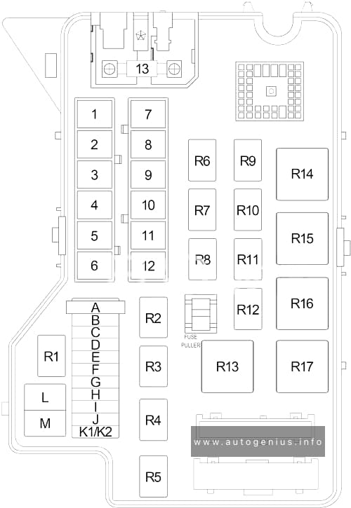
Passenger compartment fuse box
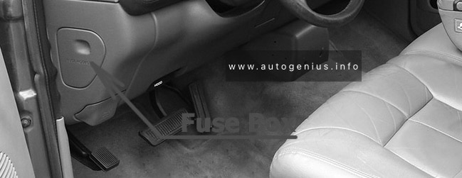
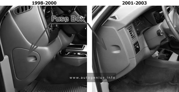
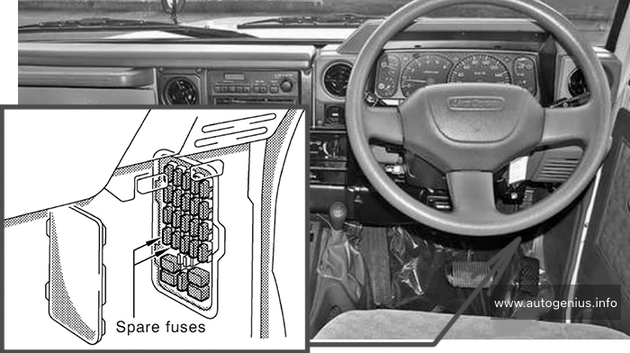
Fuse Box Location
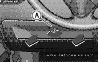
The fuse panel is located behind an access panel on left edge of the instrument panel.
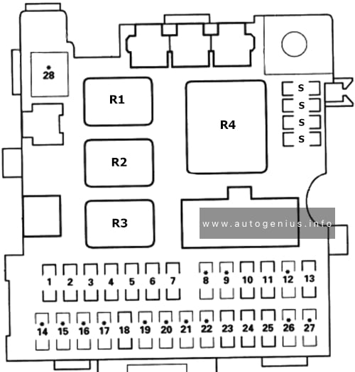
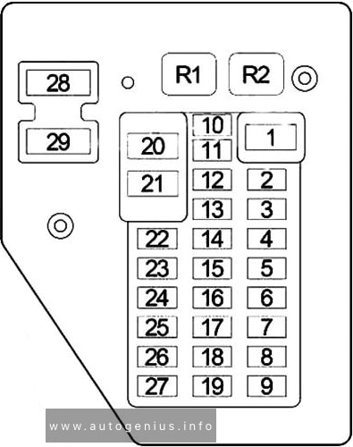
Fuse Box Diagram
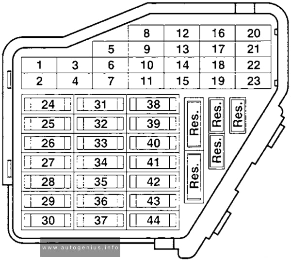
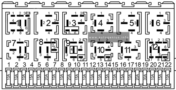
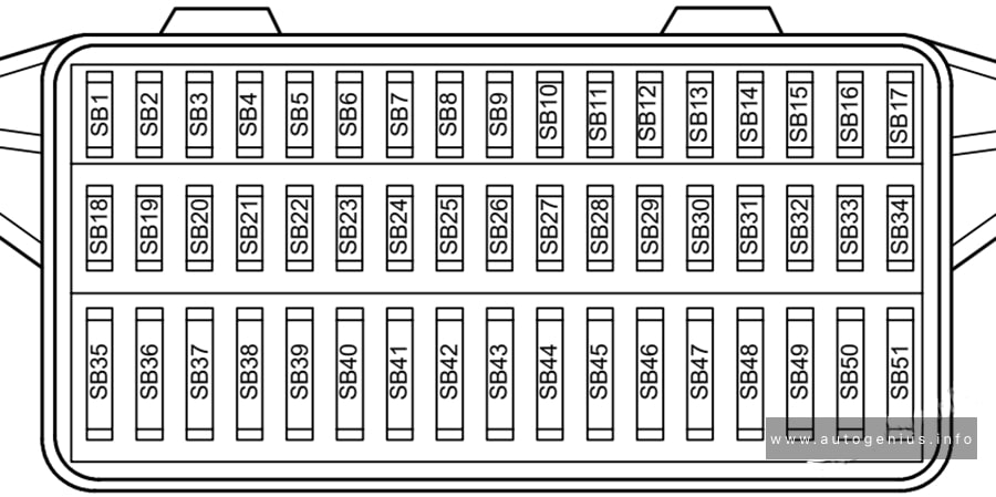
Assignment of the fuses in the instrument panel
| № | Amps | Description |
|---|---|---|
| 1 | 10A | Heated washer nozzles, glove compartment light, memory seat |
| 2 | 10A | Turn signal system |
| 3 | 5A | Fog light relay, instrument panel dimmer switch |
| 4 | 5A | License plate light |
| 5 | 7.5A | Comfort system, cruise control, Climatronic, A/C, heated seat control modules, day/night dimming mirror, control module and control unit for multi-function steering wheel |
| 6 | 5A | Central locking system |
| 7 | 10A | Back-up lights, speedometer vehicle speed sensor |
| 8 | – | – |
| 9 | 5A | Anti-lock brakes (ABS) |
| 10 | 5A/10A | Engine control module (ECM) |
| 11 | 5A | Instrument cluster, shift lock solenoid |
| 12 | 7.5A | B+ (battery positive voltage) for Data Link Connector (DLC) |
| 13 | 10A | Brake lights |
| 14 | 10A | Interior lights, central locking system |
| 15 | 5A | Instrument cluster, automatic transmission control module (TCM) |
| 16 | 10A | A/C clutch, after-run coolant pump |
| 17 | – | – |
| 18 | 10A | High beam right |
| 19 | 10A | High beam left |
| 20 | 15A | Low beam right |
| 21 | 15A | Low beam left |
| 22 | 5A | Parking and side marker lights, right |
| 23 | 5A | Parking and side marker lights, left |
| 24 | 20A | Front wiper motor, washer pump |
| 25 | 25A | Fresh air blower, Climatronic, A/C |
| 26 | 25A | Rear window defogger |
| 27 | 15A | Rear wiper motor |
| 28 | 15A | Fuel pump, gasoline |
| 29 | 10A/15A | Engine control module (ECM) |
| 30 | 20A | Sunroof control module |
| 31 | 20A | Automatic transmission control module |
| 32 | 10A/15A | Fuel Injectors (gasoline) ECM (diesel) |
| 33 | 20A | Headlight washer system |
| 34 | 10A | Engine control elements |
| 35 | 30A | 12V power outlet (in luggage comp.) |
| 36 | 15A | Fog lights |
| 37 | 10A | Radio terminal 86S, instrument cluster |
| 38 | 15A | Central locking system (with power windows) luggage compartment light, remote fuel tank door, rear lid unlock |
| 39 | 15A | Emergency flashers |
| 40 | 20A | Dual tone horn |
| 41 | 15A | Cigarette lighter |
| 42 | 25A | Radio system |
| 43 | 10A | Engine control elements |
| 44 | 15A | Heated seats |
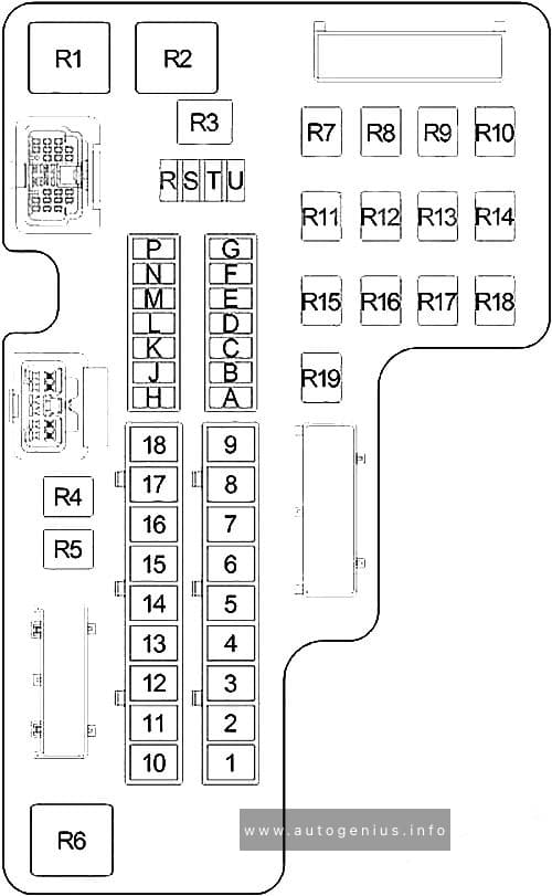
Relays
Relay Box Location
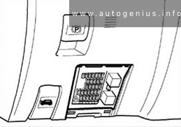
The relay panel is located under the left side of the instrument panel.
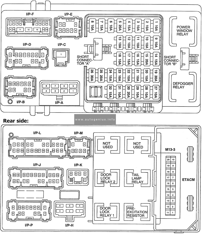
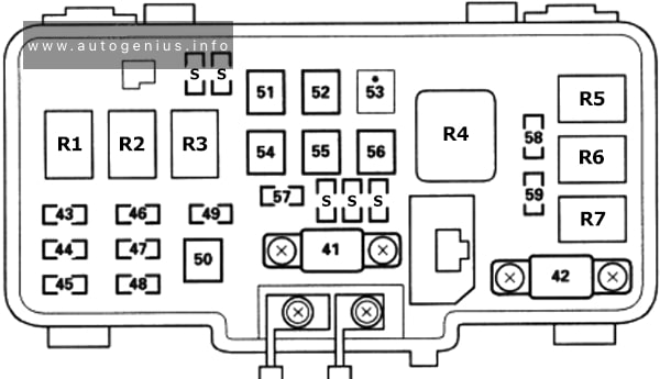
Fuse Box Diagram
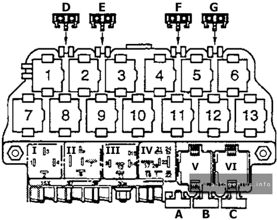
Assignment of the fuses in the relays panel
| № | Amps | Description |
|---|---|---|
| I | Dual horn relay | |
| II | Load reduction relay | |
| III | – | |
| IV | Fuel pump relay | |
| V, VI | Wiper/Washer intermittent relay | |
| 1 | – | |
| 2 | Rear lid remote unlock motor relay | |
| 3 | Anti-thett starter lock relay (clutch pedal switch) | |
| 4 | Fog light relay | |
| 5 | Multi-function steering wheel relay | |
| 6 | Multi-function steering wheel relay | |
| 7 | Daytime running lights (from April 1999) | |
| 8 | Daytime running lights (through March 1999) | |
| 9 | – | |
| 10 | Glow plug relay | |
| 11 | Park/Neutral position relay | |
| 12 | Power supply (terminal 30b, B+) relay | |
| 13 | – | |
| A | Power (Memory) seat circuit breaker | |
| B | – | |
| C | Power windows, central locking, heated power mirrors | |
| D | – | |
| E | – | |
| F | 15A | Central locking, anti-theft warning |
| G | 15A | Central locking, anti-theft warning |
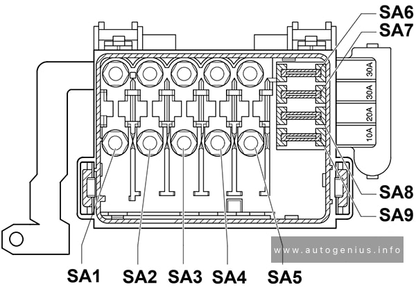
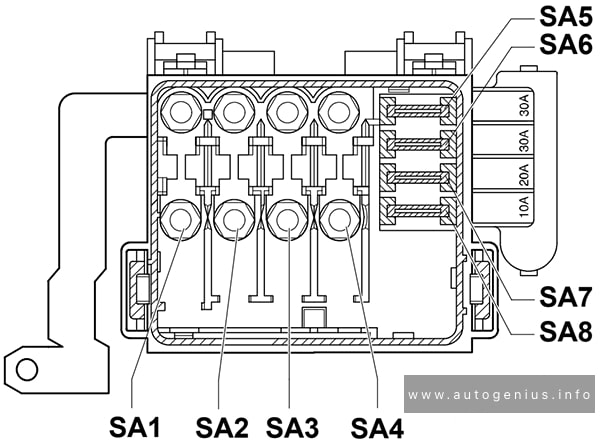
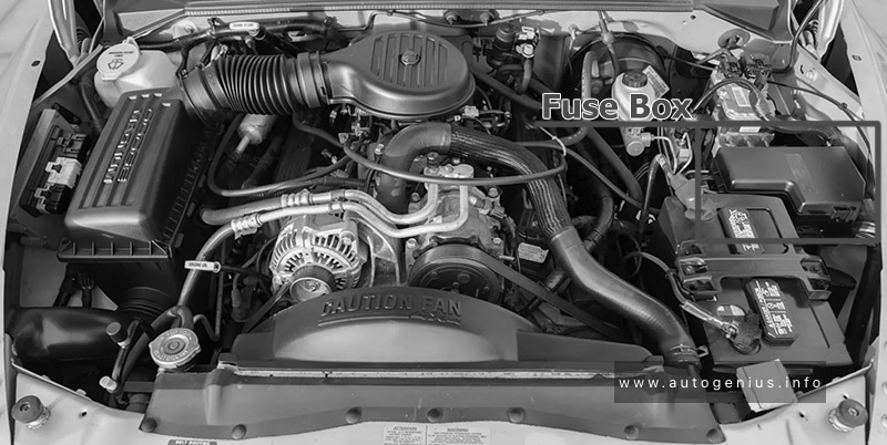
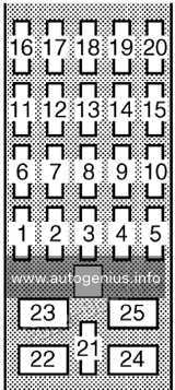
Engine compartment fuse box
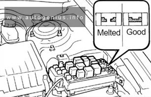
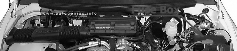
Fuse Box Location
The main fuse box located on top of the battery in the engine compartment. It contains special fuses for high current applications and prevents the main wiring harness in the event of a short circuit.
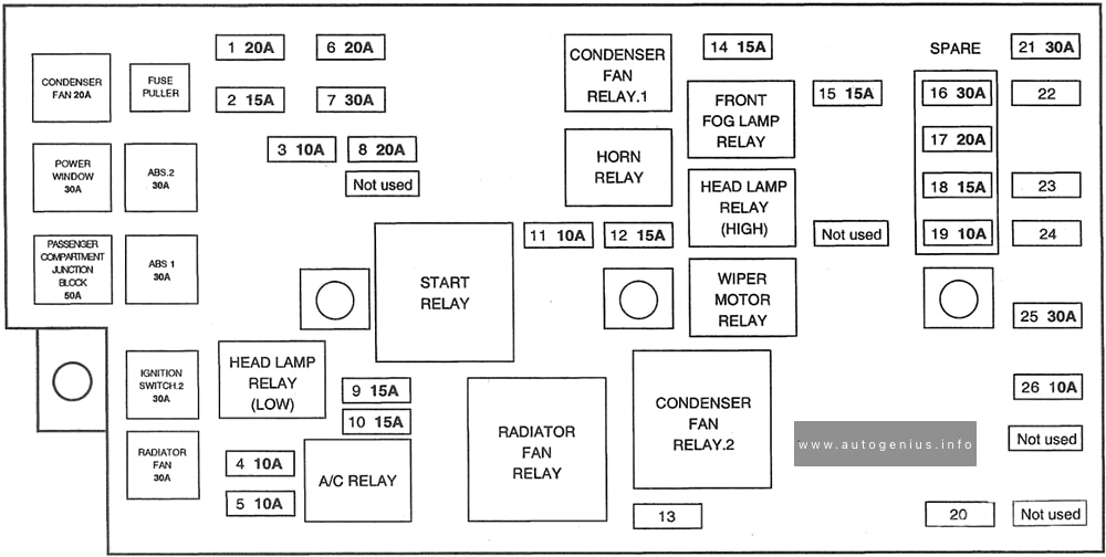
Fuse Box Diagram
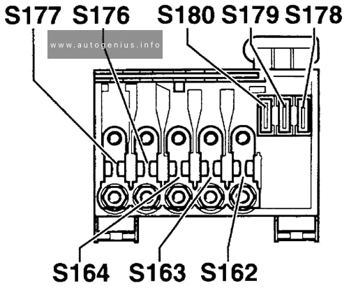
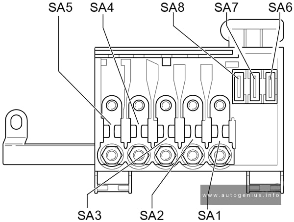
Assignment of the fuses in the engine compartment
| № | Amps | Description |
|---|---|---|
| S162 | 50A | Secondary air injection relay or coolant pre-heating relays |
| S163 | 50A | Fuel pump relay or glow plug relay |
| S164 | 40A | Coolant fan and control module |
| S176 | 110A | Interior relay panel |
| S177 | 110A/150A | Generator |
| S178 | 30A | ABS-hydraulic pump |
| S179 | 30A | ABS |
| S180 | 30A | Coolant fan |
WARNING: Terminal and harness assignments for individual connectors will vary depending on vehicle equipment level, model, and market.