This article covers the facelifted third-generation Mitsubishi L200, produced from 2002 to 2005. It includes fuse box diagrams for the 2002, 2003, 2004, and 2005 models, along with details on the location of the fuse panels inside the vehicle and the function of each fuse (fuse layout).
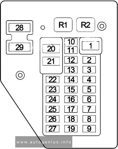
Passenger Compartment Fuse Box
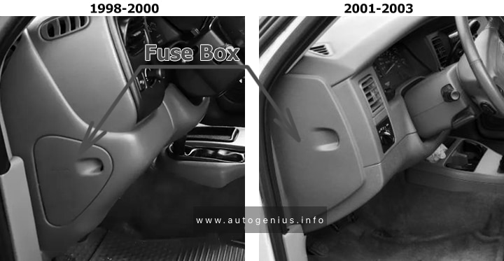
Fuse box location
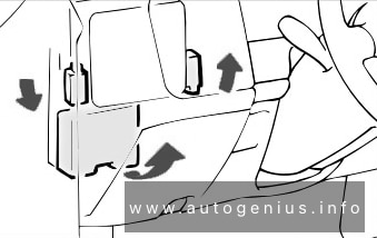
The fuse box is located in the instrument panel (on the left side). You may have to remove some trim pieces to access it.
Year of production: 2000, 2001, 2002, 2003, 2004, 2005
This article covers the fourth-generation Volkswagen Jetta (A4, Typ 1J), manufactured from 1999 to 2005. It includes fuse box diagrams for the 2000, 2001, 2002, 2003, 2004, and 2005 models, provides details on the locations of the fuse panels within the vehicle, and explains the function of each fuse (fuse layout) and relay.
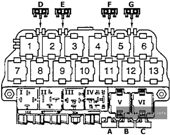
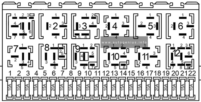
Passenger compartment fuse box
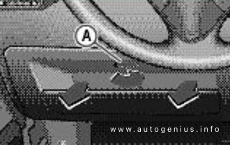
Fuse Box Location
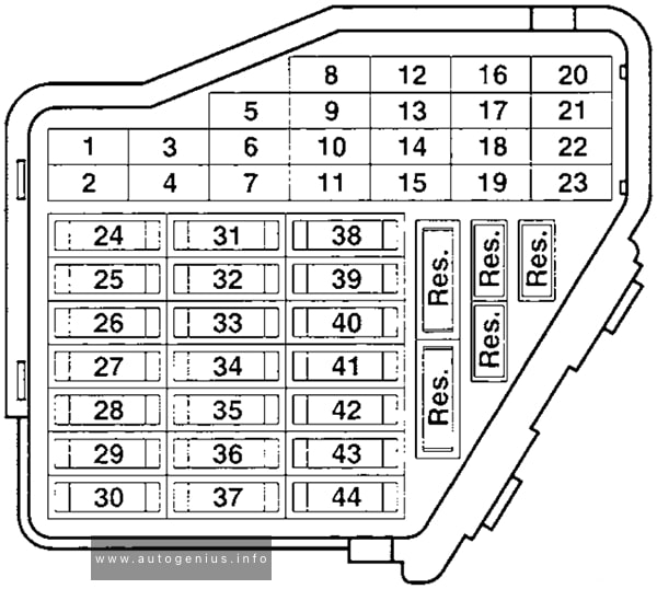
The fuse panel is located behind an access panel on left edge of the instrument panel.
Comfort system, cruise control, Climatronic, A/C, heated seat control modules, day/night dimming mirror, control module and control unit for multi-function steering wheel
6
5A
Central locking system
7
10A
Back-up lights, speedometer vehicle speed sensor
8
–
–
9
5A
Anti-lock brakes (ABS)
10
5A/10A
Engine control module (ECM)
11
5A
Instrument cluster, shift lock solenoid
12
7.5A
B+ (battery positive voltage) for Data Link Connector (DLC)
13
10A
Brake lights
14
10A
Interior lights, central locking system
15
5A
Instrument cluster, automatic transmission control module (TCM)
16
10A
A/C clutch, after-run coolant pump
17
–
–
18
10A
High beam right
19
10A
High beam left
20
15A
Low beam right
21
15A
Low beam left
22
5A
Parking and side marker lights, right
23
5A
Parking and side marker lights, left
24
20A
Front wiper motor, washer pump
25
25A
Fresh air blower, Climatronic, A/C
26
25A
Rear window defogger
27
15A
Rear wiper motor
28
15A
Fuel pump, gasoline
29
10A/15A
Engine control module (ECM)
30
20A
Sunroof control module
31
20A
Automatic transmission control module
32
10A/15A
Fuel Injectors (gasoline)
ECM (diesel)
33
20A
Headlight washer system
34
10A
Engine control elements
35
30A
12V power outlet (in luggage comp.)
36
15A
Fog lights
37
10A
Radio terminal 86S, instrument cluster
38
15A
Central locking system (with power windows) luggage compartment light, remote fuel tank door, rear lid unlock
39
15A
Emergency flashers
40
20A
Dual tone horn
41
15A
Cigarette lighter
42
25A
Radio system
43
10A
Engine control elements
44
15A
Heated seats
Relays
Relay Box Location
The relay panel is located under the left side of the instrument panel.
Power windows, central locking, heated power mirrors
D
–
E
–
F
15A
Central locking, anti-theft warning
G
15A
Central locking, anti-theft warning
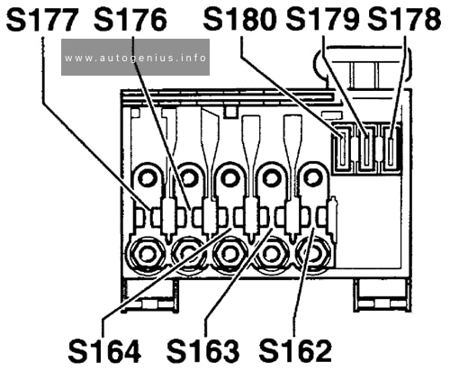
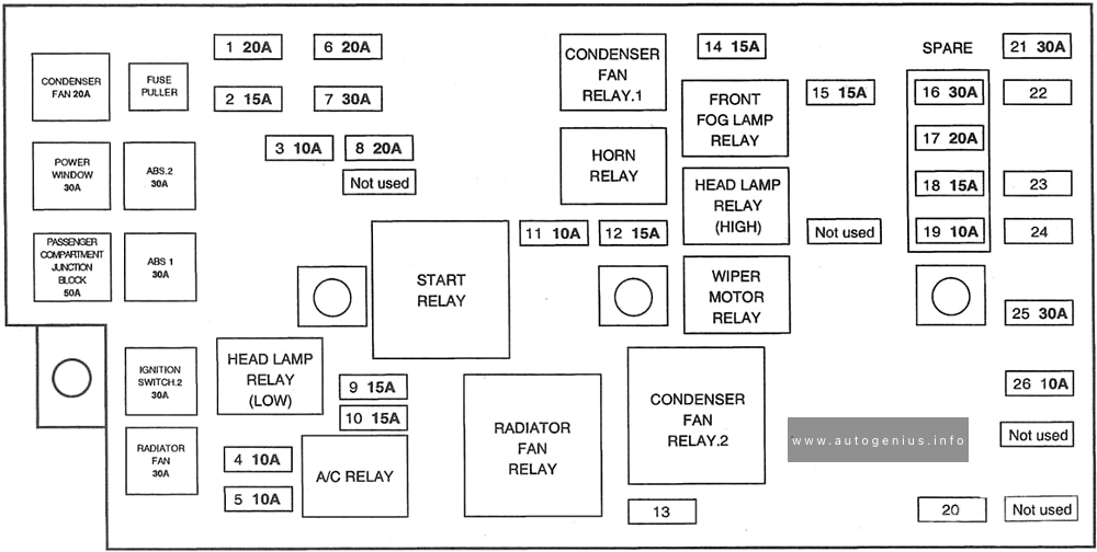
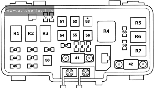
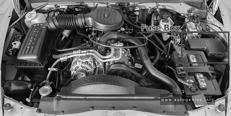
Engine compartment fuse box
Fuse Box Location
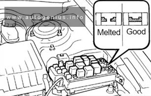
The main fuse box located on top of the battery in the engine compartment. It contains special fuses for high current applications and prevents the main wiring harness in the event of a short circuit.
The SEAT Inca (Typ 9K) was manufactured from 1996 to 2004. This article provides fuse box diagrams for the 2000, 2001, 2002, 2003, and 2004 models, along with details on the locations of the fuse panels within the vehicle and the functions of each fuse (fuse layout) and relay.
Passenger compartment fuse box
Fuse Box Location
Take hold of the ends of the cover with both hands and pull outwards until it is removed from its housings.
Relay positions above relay carrier: The control number is given in the brackets after the component designation.
The relay positions may, depending on model equipment, engine or version, differ.
Lights switched on and radio relay (292)
2-speed radiator fan relay (no air conditioning system) (80)
2-speed radiator fan relay (no air conditioning system) (53)
The Hyundai Trajet was manufactured from 1999 to 2008. This article features fuse box diagrams for the 2000, 2001, 2002, 2003, and 2004 models, provides details on the locations of the fuse panels within the vehicle, and explains the function of each fuse (fuse layout) and relay.
Passenger compartment fuse box
Fuse Box Location
The fuse box is located low on the dashboard on the driver’s side.
Year of production: 1999, 2000, 2001, 2002, 2003, 2004, 2005, 2006
This article covers the first-generation Honda HR-V (GH), manufactured from 1999 to 2006. It includes fuse box diagrams for the Honda HR-V models from 1999 to 2006, details the locations of the fuse panels within the vehicle, and explains the function of each fuse and relay (fuse layout).
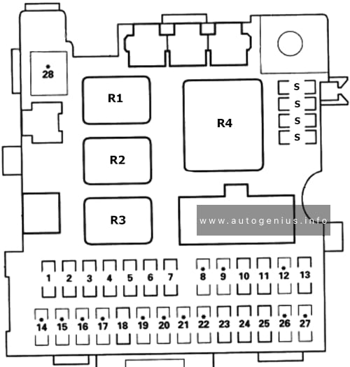
Passenger Compartment Fuse Panel
Fuse Box Location
The fuses are located under the dashboard on the driver’s side
SRS unit (VA)
Inertia switch (KG and KE models), PGM-FI main relay (Except KG and KE models)
3
20A
Windshield wiper motor, windshield washer motor
4
10A
Headlight adjuster switch (KG and KE models), headlight adjuster unit (KG and KE models), rear window intermittent wiper control unit (KG and KE models), rear window washer motor, rear window wiper motor, power window master switch, power window relay
5
10A
Integrated control unit, turn signal/hazard relay, back-up lights
6
7.5A
Gauge Assembly, Clock, vehicle speed alarm unit (KY model), seat belt alarm unit (KY and KQ models), keyless door lock control unit, secondary HO2S (KG, KE, KN and KQ models), ELD unit (CVT), alternator, VSS, primary HO2S (KG, KE and KU models), PCM, EVAP purge control solenoid valve (KG, KY, KE and KU models)
7
15A
Distributor
8
–
Not used
9
–
Not used
10
15A
Rear window defogger
11
7.5A
Blower motor relay, radiator fan relay, condenser fan relay, A/C switch, A/C compressor clutch relay, recirculation control motor, A/C thermostat, ABS modulator assembly, power mirror actuator, power mirror defogger (KG model), power mirror retract actuator (with keyless entry system), seat heater main relay (KG model)
12
–
Not used
13
7.5A
ECM/PCM, PGM-FI main relay
14
–
Not used
15
–
Not used
16
–
Not used
17
–
Not used
18
15A
Audio unit, cigarette lighter
19
–
Not used
20
–
Not used
21
–
Not used
22
–
Not used
23
7.5A
Clock, seat belt alarm unit (KY and KQ models), intregated control unit, ceiling lights, immobiliser indicator light (KG, KE, KQ and KU models), cargo area light, ECM/PCM
24
15A
Audio unit
25
15A
Keyless / power door lock control unit
26
–
Not used
27
–
Not used
28
–
Not used
S
Spare fuses
R1
Power window relay
R2
Taillight relay
R3
Seat heater main relay (KG model)
Shift lock relay (KQ and KU models with CVT)
Year of production: 2000, 2001, 2002, 2003, 2004,2005, 2006
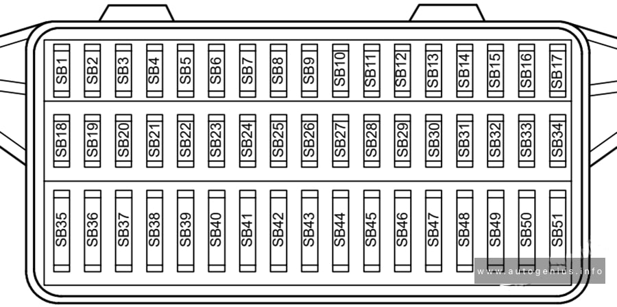
Volkswagen Lupo was produced mainly in the body of a 3-door hatchback in 1998, 1999, 2000, 2001, 2002, 2003, 2004, 2005 and 2006. Positioned as a city car with low fuel consumption. In this material you will find a designation of the purpose of fuses and relays in Volkswagen Lupo, diagrams of the boxes in which they are located.
Passenger compartment
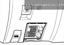
Fuse box location
The fuse panel is located behind the cover on the driver’s side of dash panel.
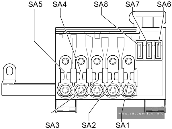
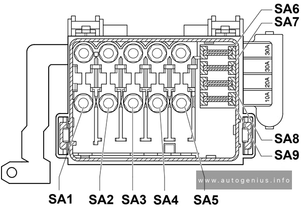
Fuse carrier B Fuse SA2 is located in luggage compartment next to battery
SA3
50A
Engine glow plugs
SA4
80A
Electro-hydraulic power steering motor (ARR, AYZ)
Coolant heater elements (ARR, AYZ)
Radiator fan control unit (only models with air conditioner, ARR, AYZ)
Radiator fan (ARR, AYZ)
SA5
30A
Radiator fan (AMF)
SA6
30A
ABS with EDL control unit
SA7
30A
ABS with EDL control unit
SA8
10A/20A
Radiator fan (AVY, ARR)
Radiator fan control unit (only models with air conditioner, AVY, ARR)
SA9
30A/10A
Radiator fan control unit (only models with air conditioner, AVY, ARR)
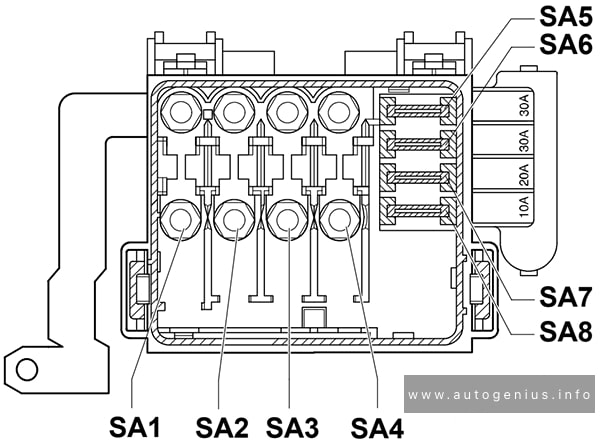
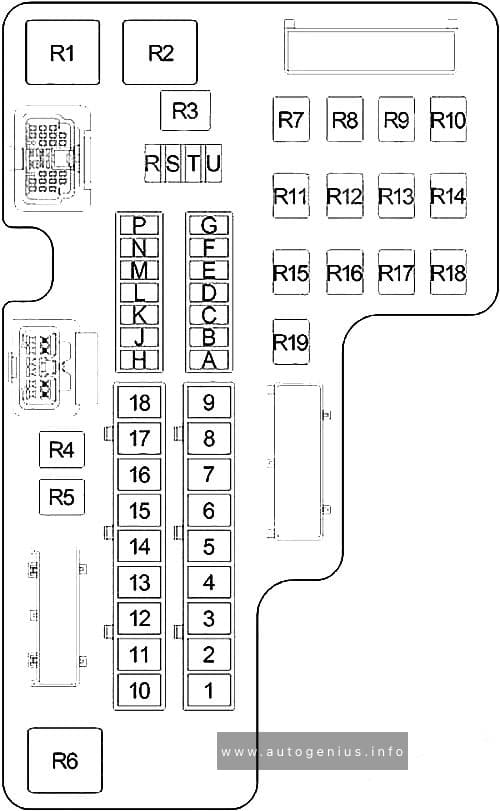
WARNING: Terminal and harness assignments for individual connectors will vary depending on vehicle equipment level, model, and market.
Sentry Key Immobilizer, Instrument Cluster, Radio, Center Console Lamp, Overhead Console, Front/Rear Dome Lamp, Glove Box Lamp/Switch, Data Link Connector, Driver Door Module, Right/Left Visor/Vanity Mirror & Liftgate Lamp
2
20A
Horn Relay & Clockspring
3
–
–
4
20A
Central Timer Module, Headlamp Switch, Left/Right Tail Lamp Assembly, Left/Right Front Park/Turn Signal Lamps, Left/Right Front Side Marker Lamp & License Plate Lamp
5
20A
Front Wiper Relay, Front Wiper Motor & Central Timer Module
6
–
–
7
–
–
8
10A
Transmission Control Module & Instrument Cluster
9
5A
Rear A/C Heater Control, Overhead Console, Transfer Case Selector Switch, Shift Bezel Lamp, Radio, Cigar Lighter, A/C Heater Control & Instrument Cluster
10
10A
Powertrain Control Module, Fuel Pump Relay, Radiator Fan Relay & Sentry Key Immobilizer
11
10A
A/C Compressor, Proportional Purge Solenoid, Automatic Day/Night Mirror, Overhead Console, Central Timer Module & Transfer Case Selector Switch
12
10A
Engine Starter Motor Relay & Transmission Control Module
Toyota Land Cruiser (70, AU 78/79; 2000 – 2006) – fuse and relay box diagram
Year of production: 2000, 2001, 2002, 2003, 2004, 2005, 2006
This article provides fuse box diagrams for the Toyota Land Cruiser 78/79 (Australia) models from 2000 to 2006. It also includes details on the location of the fuse panels within the vehicle and explains the function and layout of each fuse.
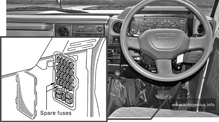
Passenger Compartment Fuse Boxes
Fuse Box Location
Remove the lid to access.
Toyota Land Cruiser (2000 – 2006) – fuse and relay box – location passenger compartment
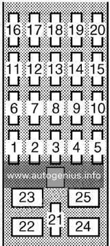
Fuse Box Diagrams
Toyota Land Cruiser (2000 – 2006) – fuse and relay box diagram – passenger compartment
Assignment of the fuses under the instrument panel
№
Name
Amp
Description
1
SPARE
7.5A
Spare fuse
2
SPARE
15A
Spare fuse
3
CHARGE
7.5A
Gasoline: No circuit
IGN
7.5A
1HD-FTE engine: Electronically controlled fuel injection pump system
4
CIG
15A
Cigarette lighter, clock, radio
5
EFI
15A
Gasoline: Multiport fuel injection system / sequential multiport fuel injection system
ECD
15A
1HD-FTE engine: Electronically controlled fuel injection pump system
6
A.C
10A
Air conditioning system
7
TURN
10A
Turn signals lights
8
DEFOG
15A
No circuit
9
WIPER
20A
Windshield wipers and washer, rear window wiper and washer, back-up lights
10
ENGINE
15A
Charging system, emission control system, gauges and meters, service reminder indicators and warning buzzer
11
ST
30A
Diesel: Starting system
12
STOP
10A
Stop lights
13
DOME
10A
Interior light, luggage compartment light, clock, radio
14
RADIO
10A
Diesel: No circuit
15
ECU-B
10A
Diesel; 2003-2006: Exhaust gas recirculation system
Toyota Tarago (2003 – 2005) – fuse and relay box diagram
Year of production: 2003, 2004, 2005
The Toyota Tarago (2003-2005) is an Australian-market version of the globally known Toyota Previa or Estima, and it is a versatile multi-purpose vehicle (MPV) designed to accommodate large families or serve as a people mover. Known for its spacious interior, comfort, and reliable engineering, the Tarago was a popular choice in the minivan segment in Australia during this time. It offered a balance of practicality, comfort, and performance for long journeys and daily use.
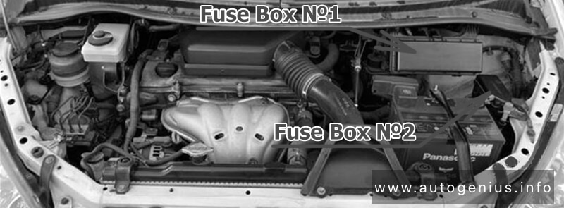
Passenger Compartment Fuse Boxes
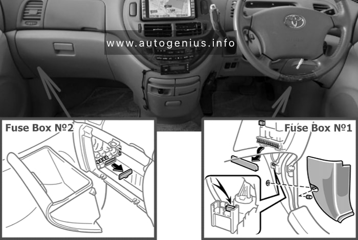
Fuse Box Location
Toyota Tarago (2003 – 2005) – fuse and relay box location – passenger compartment
Fuse Box Diagrams
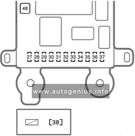
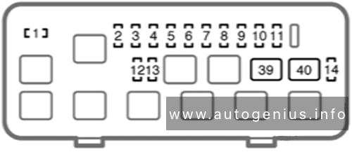
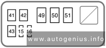
Fuse Box №1
Toyota Tarago (2003 – 2005) – fuse and relay box diagram – passenger compartment (fuse box no. 1)
Assignment of the fuses in the Fuse Box №1 (driver’s side)
№
Name
Amp
Description
27
STOP
15A
Stoplights, high mounted stoplight
28
GAUGE
10A
Gauges and meters, air conditioning system, service reminder indicators
29
A/C
7.5A
Air conditioning system
30
S-HTR (R)
10A
Seat heater (right)
31
S-HTR (L)
10A
Seat heater (left)
32
IGN
15A
Gauges and meters, changing system, SRS airbag system, multiport fuel injection system / sequential multiport fuel injection system
33
ECU-IG
15A
Rear window defogger, anti-lock brake system, power windows multiport fuel injection system / sequential multiport fuel injection system
34
WIP
30A
Windshield wipers and washer, rear window wiper and washer
35
RR DOOR
30A
No circuit
36
AM1
7.5A
Starter system
37
OBD II
7.5A
On-board diagnosis system
38
MET
7.5A
Gauges and meters
48
RR HTR
30A
Heater system, gauges and meters
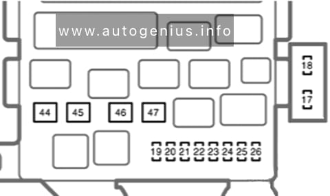
Fuse Box №2
Toyota Tarago (2003 – 2005) – fuse and relay box diagram – passenger compartment (fuse box no. 2)
Assignment of the fuses in the Fuse Box №2 (passenger’s side)
№
Name
Amp
Description
17
P/OUTLET
15A
Power outlet
18
CIG
15A
Car audio system, cigarette lighter, power rear view mirrors
The Toyota Previa (2003-2005) is a multi-purpose vehicle (MPV) or minivan, known for its spacious interior, family-friendly design, and reliable performance. In various markets, including some parts of Asia and Europe, it was also sold under the name Toyota Estima. The Previa was designed to offer practicality, comfort, and a smooth driving experience, making it a popular choice for families and individuals seeking a versatile vehicle.