Lincoln Aviator (UN152; 2004) – fuse and relay box diagram
Year of production: 2002, 2003
This article focuses on the first-generation Lincoln Aviator (UN152), manufactured between 2002 and 2005. It includes fuse box diagrams for the 2004 models, provides information on the location of the fuse panels within the vehicle, and explains the function and layout of each fuse and relay.
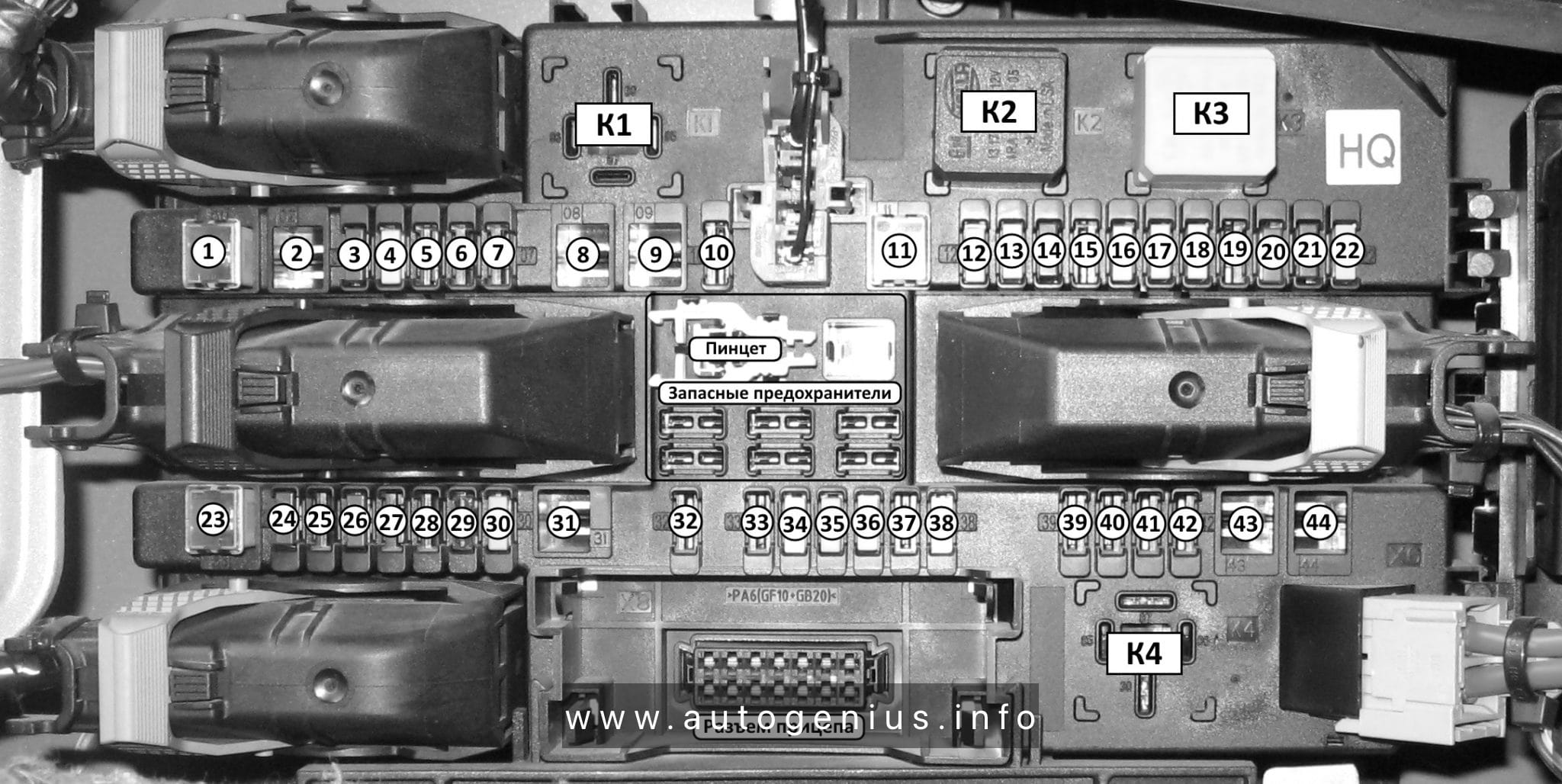
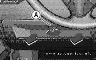
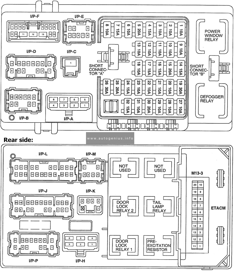
Passenger compartment fuse panel
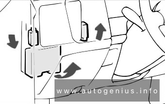
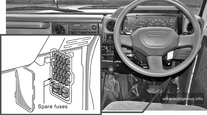
Fuse box location
The fuse panel is located under the instrument panel to the left of the steering column. The relays are located on the reverse side of the passenger compartment fuse panel. To access the relays, you must remove the fuse panel.
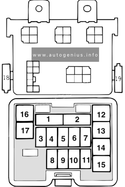
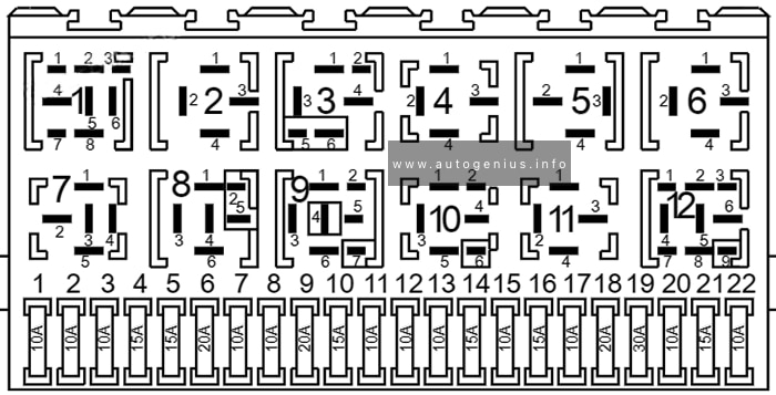
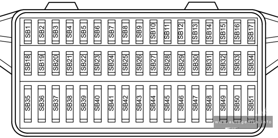
Fuse box diagram
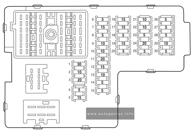
Assignment of the fuses in the Instrument panel (2004)
| № | Amp Rating | Description |
|---|---|---|
| 1 | 30A | Moonroof motor, Driver seat lumbar switch |
| 2 | 10A | VAPS module, Memory seat module, Body security module, Tire Pressure Monitor System (TPMS), Sunload/Autolamp sensor (SecuriLock LED) |
| 3 | 20A | Radio, Navigation system |
| 4 | 5A | Front wiper module |
| 5 | 15A | Flasher relay (turn/hazards) |
| 6 | 5A | Electronic Hidden Antenna Module (EHAM) (antenna amplifier), Radio, Moonroof motor, Driver window motor, Navigation |
| 7 | 15A | Heated mirrors, DEATC module |
| 8 | 5A | Daytime Running Lamps (DRL) module, Heated PCV valve |
| 9 | 10A | Back-up lamps (DTRS), Electrochromatic mirror |
| 10 | 10A | Heated backlight relay coil, Climate seat modules, Auxiliary A/C temperature blend/mode actuator, A/C clutch relay contact |
| 11 | 20A | Not used (spare) |
| 12 | 15A | Restraints module |
| 13 | 10A | Brake shift interlock |
| 14 | 5A | Not used (spare) |
| 15 | 5A | Instrument cluster, Rear wiper module, TPMS |
| 16 | 20A | Cigar lighter, OBD II |
| 17 | 15A | Delayed accessory relay coil, Battery saver relay coil and contacts |
| 18 | 5A | Not used (spare) |
| 19 | 15A | Washer pump |
| 20 | 5A | Shifter, Clock, Power mirror switch, DVD |
| 21 | 10A | Brake pressure switch (ABS), IVD switch, Flasher relay |
| 22 | 10A | ABS module |
| 23 | 7.5A | Liftgate release relay coil and contacts |
| 24 | 30A | Subwoofer, Navigation |
| 25 | 5A | Trailer tow battery charge relay coil |
| 26 | 5A | SecuriLock transceiver |
| 27 | 5A | Rear park assist, VAPS module |
| 28 | 5A | Radio, Navigation |
| 29 | 10A | DTRS, Feed to Fuse 28 |
| 30 | 5A | Instrument cluster, Compass module, Auxiliary A/C relay coil |
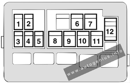
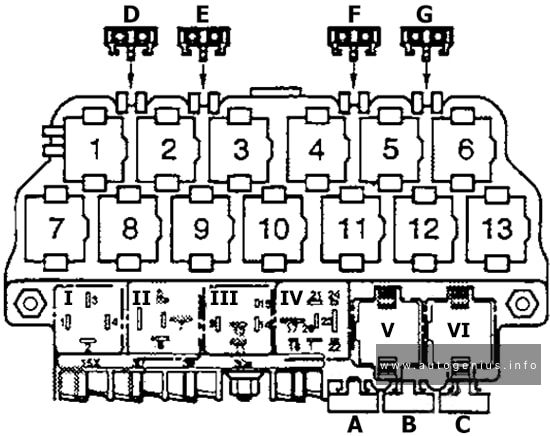
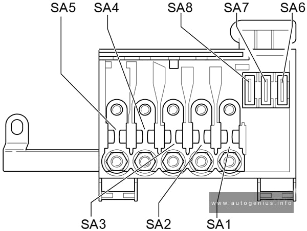
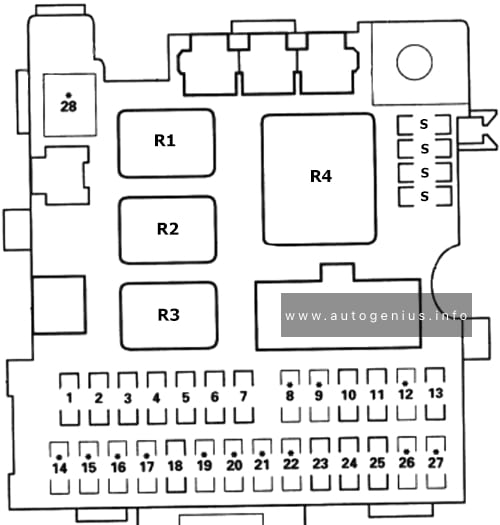
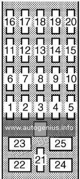
Relay in passeneger compartment (located on the reverse side of the fuse box)
Relay box diagram
Assignment of the relays in the Instrument panel (2004)
| Relay № | Description |
|---|---|
| 1 | Flasher relay |
| 2 | Heated backlight relay |
| 3 | Delayed accessory relay |
| 4 | Open |
| 5 | Batteiy saver relay |
| 6 | Open |
| 7 | Open |
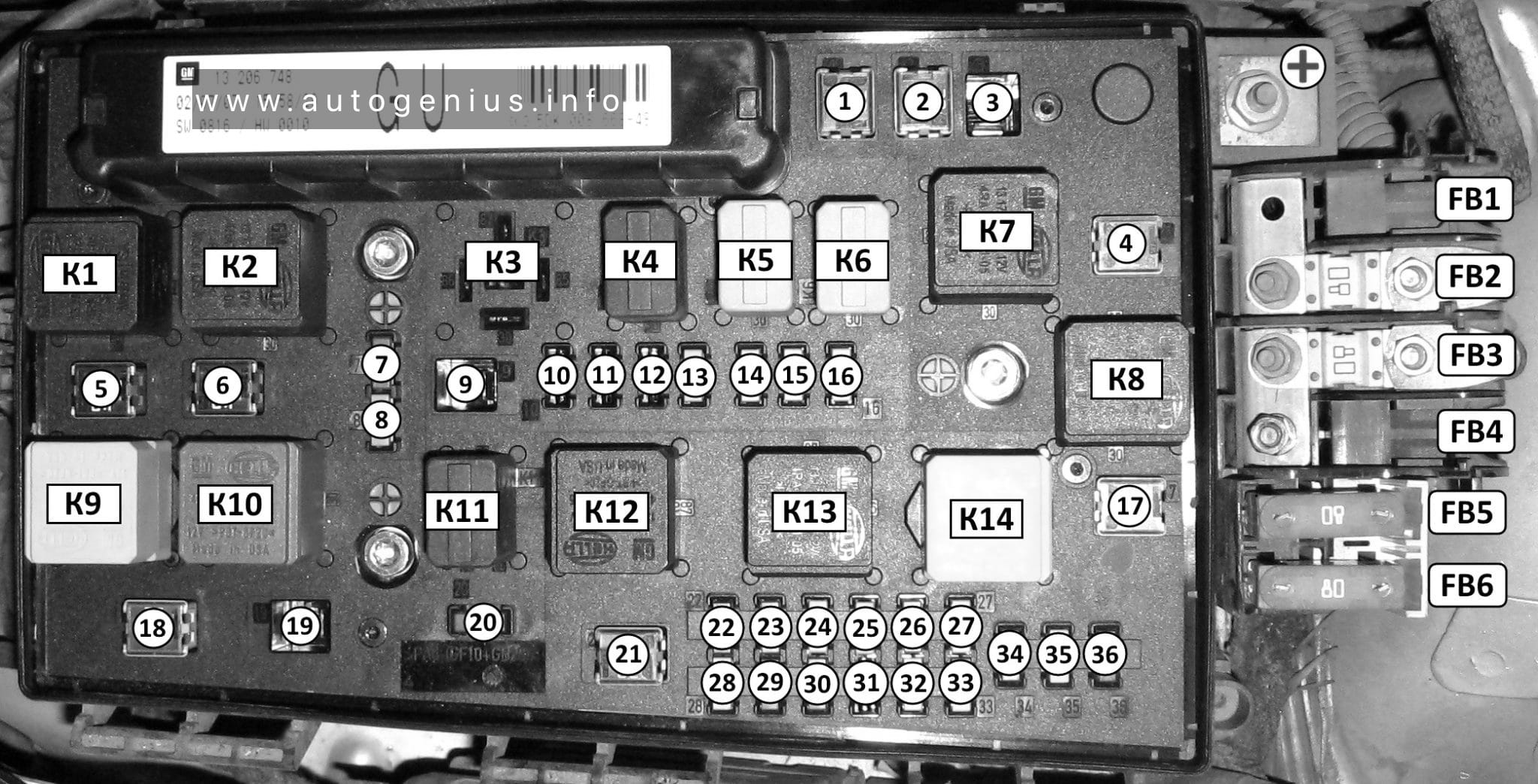
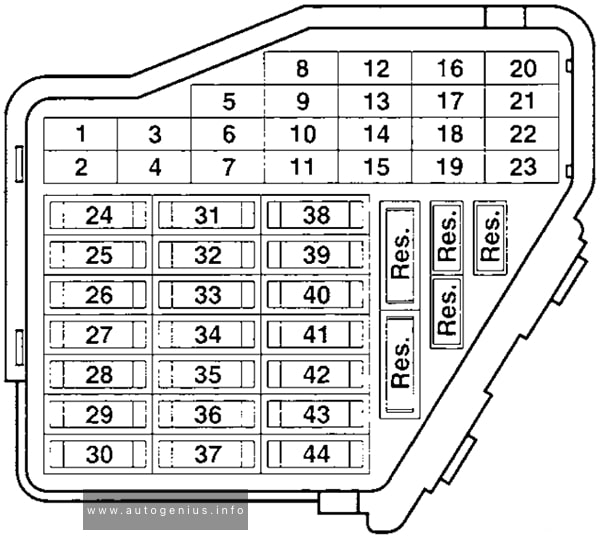
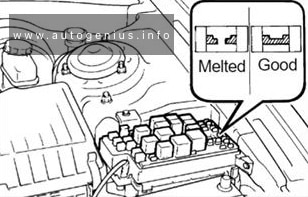
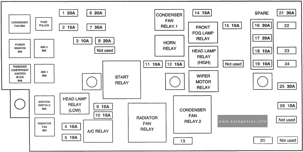
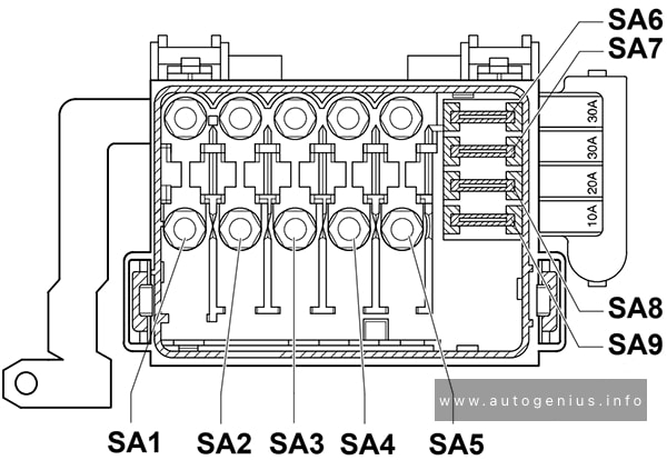
Engine compartment (power distribution box)
Fuse box diagram
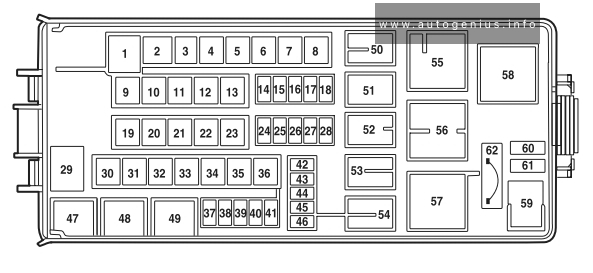
Assignment of the fuses in the engine compartment (2004)
| № | Amp Rating | Description |
|---|---|---|
| 1 | 60A | Power Junction Box (PJB) |
| 2 | 30A | Door locks (BSM) |
| 3 | — | Not used |
| 4 | 40 A | Heated backlight/mirrors |
| 5 | 40 A | Anti-lock Brake System (ABS) module (pump) |
| 6 | 60A | Delayed accessory |
| 7 | 20A | Daytime Running Lamps (DRL) module |
| 8 | 20A | Electric cooling fan |
| 9 | 20A | Headlamp switch |
| 10 | 30A | ABS module (valves) |
| 11 | 40A | PTEC relay contacts |
| 12 | 50A | Ignition/Starter relay |
| 13 | 40 A | Trailer tow relays |
| 14 | 15 A | Brake lamp feed |
| 15 | 10A | Keep alive power (PTEC/cluster/DEATC) |
| 16 | 20A | Power point #3 |
| 17 | 20A | Rear wiper module |
| 18 | 20A | 4×4 module |
| 19 | 30A | Driver window motor |
| 20 | 30A | Electric trailer brakes |
| 21 | 30A | Memory seat module |
| 22 | 20A | Main exterior lamps (low beam headlamps, high beam headlamps, fog lamps) |
| 23 | 30A | Ignition switch |
| 24 | 20A | Horn relay |
| 25 | 20A | Power point #1 |
| 26 | 20A | Fuel pump relay contacts |
| 27 | 20A | Trailer tow lamps |
| 28 | 20A | Power point #2 |
| 29 | 60A | PJB |
| 30 | 30A | Front wiper module |
| 31 | 30A | Climate-controlled seats modules |
| 32 | 30A | Passenger seat switch |
| 33 | 30A | Auxiliary blower motor |
| 34 | 20A | Right HID relay |
| 35 | 20A | Left HID relay |
| 36 | 40 A | Blower motor |
| 37 | 15 A | A/C clutch relay, TXV, Transmission, Speed control |
| 38 | 15 A | HEGO, VMV, Canister vent, IMCC-LSRC, EGR module |
| 39 | 15 A | Injectors |
| 40 | 15 A | PTEC, Mass Air Flow (MAF) sensor, Fuel pump relay |
| 41 | 25A | Coil on plug, PTEC relay |
| 42 | 10A | Right low beam (halogen) |
| 43 | 10A | Left low beam (halogen) |
| 44 | 2A | Heated PCV valve (w/DRL only) |
| 45 | 2A | Brake Pressure Switch |
| 46 | 20A | High beams/Fog lamps |
| 47 | — | Horn relay |
| 48 | — | Fuel pump relay |
| 49 | — | High beam relay |
| 50 | — | Fog lamp relay |
| 51 | — | Not used |
| 52 | — | A/C clutch relay |
| 53 | — | Trailer tow right turn relay |
| 54 | — | Trailer tow left turn relay |
| 55 | — | Blower motor relay |
| 56 | — | Starter motor relay |
| 57 | — | PTEC relay |
| 58 | — | Ignition relay |
| 59 | — | Driver brake applied relay |
| 60 | — | PCM diode |
| 61 | — | A/C clutch diode |
| 62 | 30A | Power windows (Circuit breaker) |
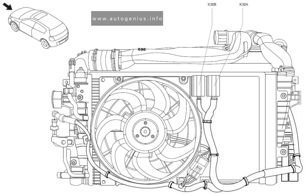
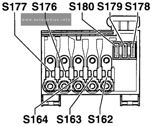
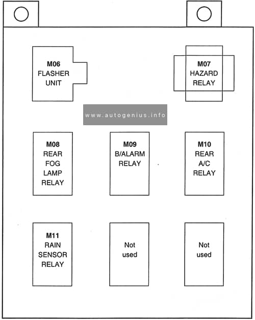
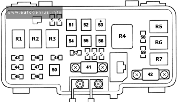
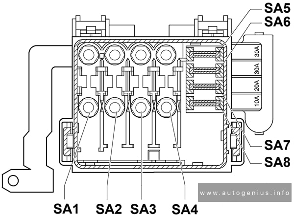
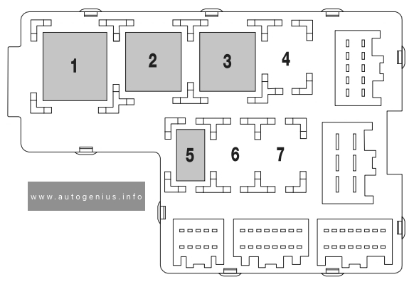
Auxiliary relay box
Relay box diagram
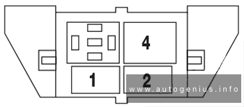
Assignment of the fuses in the auxiliary relay box (2004)
| Relay № | Description |
|---|---|
| 1 | Left HID relay (1/2 ISO) |
| 2 | Right HID relay (1/2 ISO) |
| 3 | Open |
| 4 | EDF relay (Full ISO) |
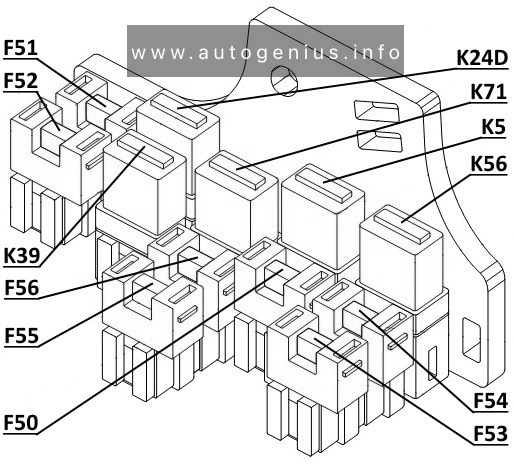
Rear relay box
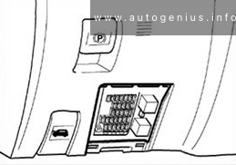
Relay box location
The relay box is located on the rear passenger side quarter trim panel.
Relay box diagram
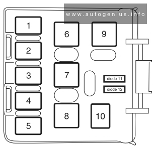
Assignment of the fuses in the rear relay box (2004)
| Relay № | Description |
|---|---|
| 1 | Liftgate release solenoid |
| 2 | Open |
| 3 | Open |
| 4 | Trailer tow back-up lamps |
| 5 | Open |
| 6 | Open |
| 7 | Trailer tow battery charge |
| 8 | Trailer tow park lamps |
| 9 | Open |
| 10 | Open |
| Diode 11 | Open |
| Diode 12 | Open |
WARNING: Terminal and harness assignments for individual connectors will vary depending on vehicle equipment level, model, and market.