Vauxhall Astra H – (2004 – 2009) – fuse and relay box diagram
Year of production: 2004, 2005, 2006, 2007, 2008, 2009
The Opel Astra H, the third generation of the Opel Astra compact-class passenger car, was produced from 2004 to 2009 with both gasoline and diesel engine options. Also marketed as the Vauxhall Astra H, this model underwent a facelift during its production period. In this article, you will find information on the locations of the control units, detailed descriptions of the Astra H fuse boxes and relays, their diagrams. Additionally, we will identify the fuse responsible for the cigarette lighter.
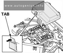
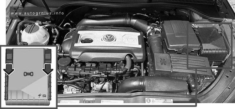
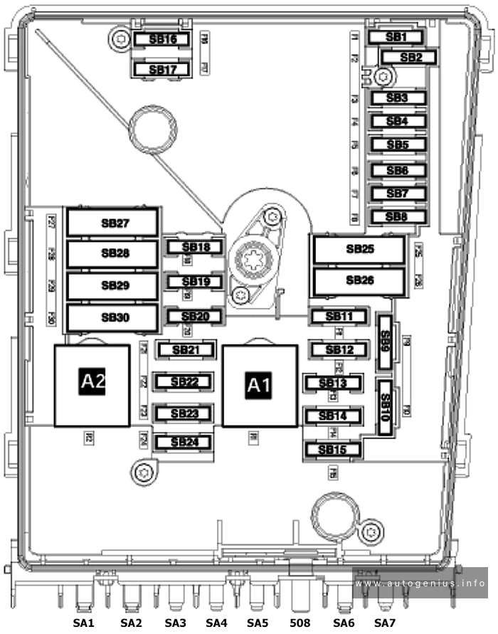
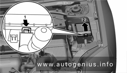
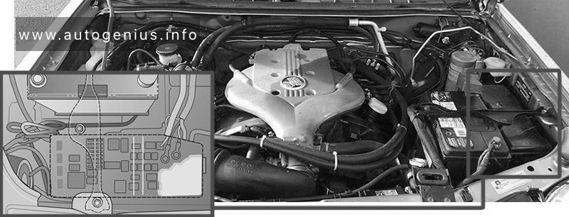
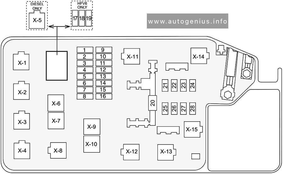
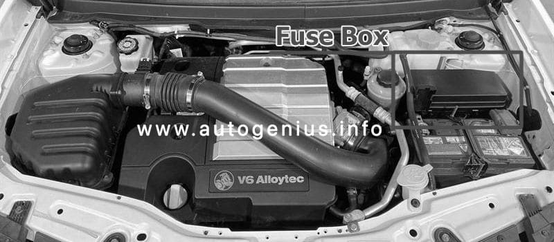
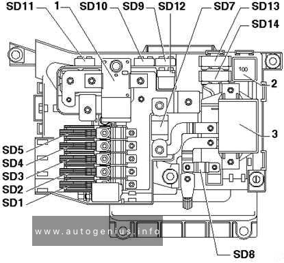
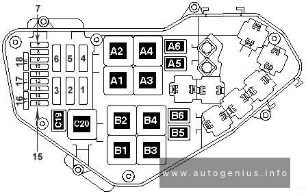
Engine compartment fuse box
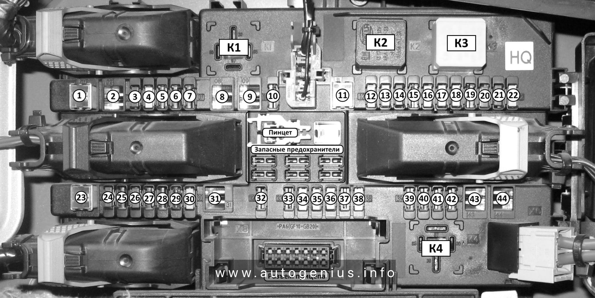
Insert a screwdriver into the opening as far as it will go and tilt it sideways. Open the cover upwards and remove. The fuse box has two different fuse assignments depending on the load compartment fuse box variant,
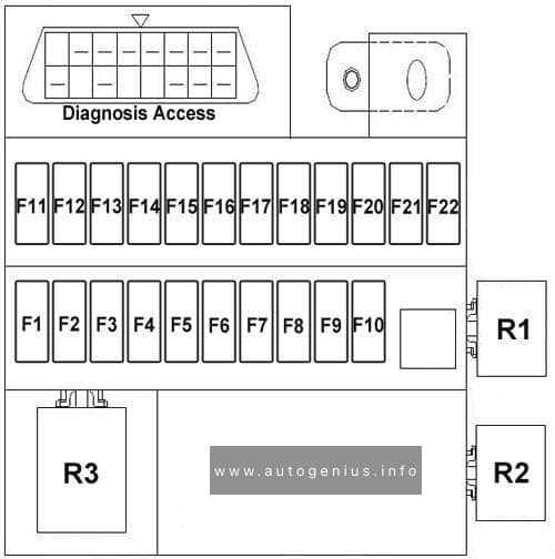
Fuse Box Diagram
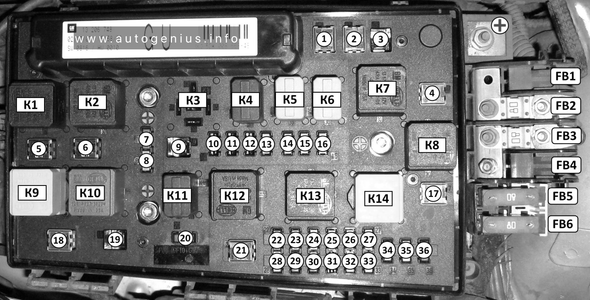
Assignment of the fuses in the engine compartment.
| № | Amp | Description |
|---|---|---|
| FB1 | 50A | Electro Hydraulic Hard Top HT |
| FB2 | 80A | Diesel (Glow time controller) |
| FB3 | 80A | EGUR |
| FB4 | 30A | Independent heater IH 100А Additional heater – electric, passenger compartment EH |
| FB5 | 80A | REC / Rear Fuse Box |
| FB6 | 80A | REC / Rear Fuse Box |
| F1 | 20A | Anti-lock braking system (ABS) |
| F2 | 30A | Anti-lock braking system (ABS) |
| F3 | 30A | Heating system, interior ventilation, climate control (HVAC) |
| F4 | 30A | Heating, ventilation and air conditioning (HVAC) |
| F5 | 30A or 40A | Radiator fan |
| F6 | 20A or 30A or 40A | Radiator fan |
| F7 | 10A | Windscreen washers (front and rear) |
| 20A | (without REC) Central locking ZV | |
| F8 | 15A | Horn |
| 10 | (without REC) Central locking ZV, Front windscreen washer, rear WA | |
| F9 | 25A | Windscreen washers (front and rear) |
| 25A | (without REC) Heated rear window HFH (K17_X125) | |
| F10 | 7,5A | To the diagnostic connector DIAG |
| F11 | 7,5A | Instruments |
| F12 | 5A | Circulation pump |
| 7,5A | (without REC) Inf. ID Display, Twin Audio TWA Audio System, DAB Digital Broadcasting, TCV Voice Control Phone | |
| F13 | 15A | Fog lamp |
| 5A | Interior lamp IRL (K18_X125) | |
| F14 | 30A | Windscreen wiper (front) |
| F15 | 30A | Windscreen wiper (rear) |
| F16 | 5A | Engine control module / Open-Start / Stop system (without REC) ABS-ESP, Sound signal (K4_X125), Air conditioning, semi-automatic air conditioning, electronic climate control, Brake light switch, el. hydraulic rigid top |
| F17 | 25A | Fuel filter heating (diesel models) |
| F18 | 25A | Starter |
| F19 | 30A | Electronic gearbox equipment |
| F20 | 10A | Air conditioner compressor, Horn (K4_X125) |
| F21 | 20A | Engine control module (ECM) |
| F22 | 7.5A | Engine control module (ECM) |
| F23 | 10A | Adaptive headlight system (AFL), headlamp leveling |
| F24 | 15A | Fuel pump |
| F25 | 15A | Electronic gearbox equipment |
| F26 | 10A | Engine control module (ECM) |
| F27 | 5A | Power steering |
| F28 | 5A | Electronic equipment of a transmission |
| F29 | 7.5A | Electronic equipment of gearbox |
| 7.5A | (with REC) Control unit gearbox Automatic / Easytronic | |
| F30 | 10A | Engine control module (ECM) |
| F31 | 10A | Adaptive headlight system (AFL). Headlamp leveling |
| 15A | (without REC) Rear window wiper (K56) | |
| F32 | 5A | Brake system fault indicator lamp, air conditioning, clutch pedal switch |
| F33 | 5A | Headlight leveling, Adaptive Forward Lighting (AFL), Outdoor light control unit |
| F34 | 7.5A | Steering column module control unit |
| F35 | 20A | Infotainment system |
| F36 | 7.5A | Mobile phone, digital radio receiver, Twin Audio system, multifunction display |
| 15A | (without REC) Cigarette lighter | |
| К1 | (K11_X125) | Radiator fan (FE5, FE6) |
| К2 | (K12_X125) | Radiator fan (FE5, FE6) |
| КЗ | (K7_X125) | (with REC) Headlight washer pump (FE9) |
| K4 | (K16_X125) | (with REC) Fog lights, front (FE13) |
| K4 | (K18_X125) | (K18_X125) (without REC) Disable download (interior lighting, etc.) (FE13) |
| К5 | K5 (K5_X125) | Wiper, windshield, low / high (FE14, FE15) |
| К6 | (K6_X125) | Wiper, windshield, ON / OFF (FE14, FE15) |
| К7 | (K15_X125) | Fan, passenger compartment – Air Conditioning / Heating (FE4) |
| К8 | (K14_X125) | (with REC) Filter heating (Diesel) (FE17) |
| (K8_X125) | (without REC) Compressor, air conditioning (FE17) | |
| K9 | (K1_X125) | Starter (FE18, K3_X125) |
| К10 | (K13_X125) | Radiator fan (FE5, FE6) |
| К11 | (K8_X125) | (with REC) Compressor, air conditioning (FE20, FE32) |
| (K4_X125) | (without REC) Horn sound signal (FE20, FE16) | |
| К12 | (K2_X125) | Engine management controller (on FE21, FE26, FE32) |
| К13 | (K10_X125) | Fuel pump (FE24) |
| К14 | (K3_X125) | Pin 15 (on K1_X125, FE23, FE24, FE25, FE27, FE29, FE30, FE31, FE33) |
| К15 | — | Heater fan relay |
| К16 | — | Fog light relay |
Individual relay elements can be located outside the main unit

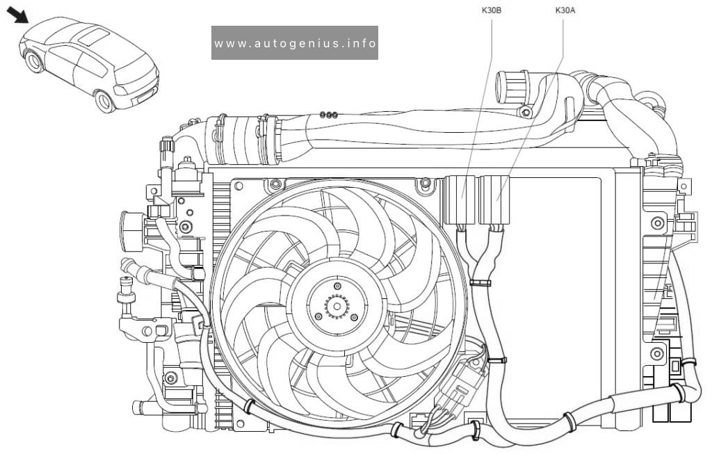
Assignment of the relays in the engine compartment
| Number | Description |
| K30A Relay | Radiator fan (FE5, FE6) |
| K30B Relay | K30B Relay – radiator fan (FE5, FE6) |
| K84LD / RD Relay | Hydraulic Unit (Convertible Top) (FB1) |
| K93 Relay | Unlocking the gear lever (Automatic transmission AF17 / 4, AF22 / 4) |
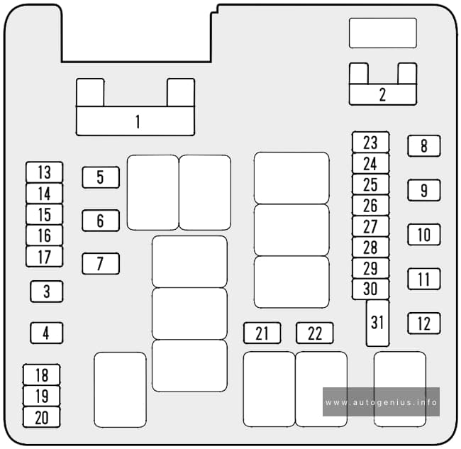
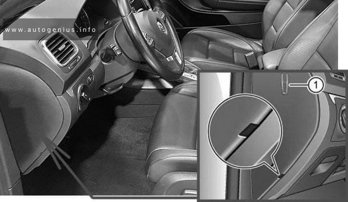
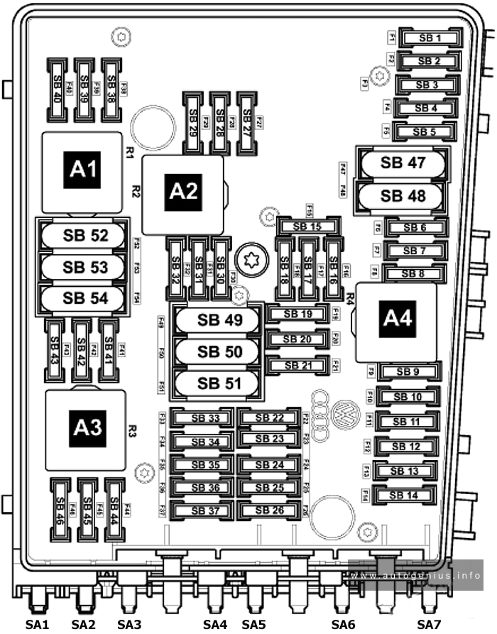
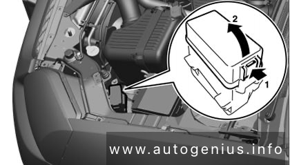
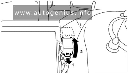
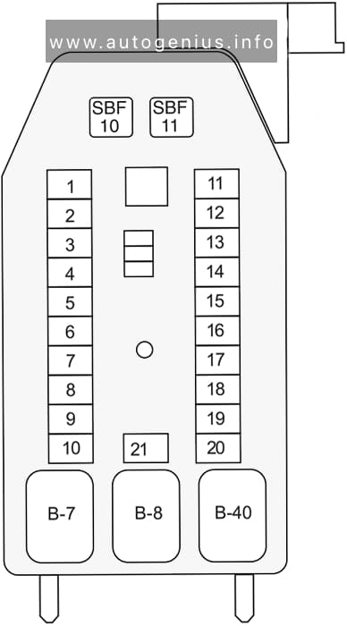
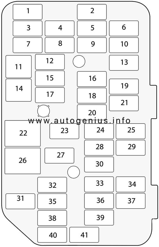
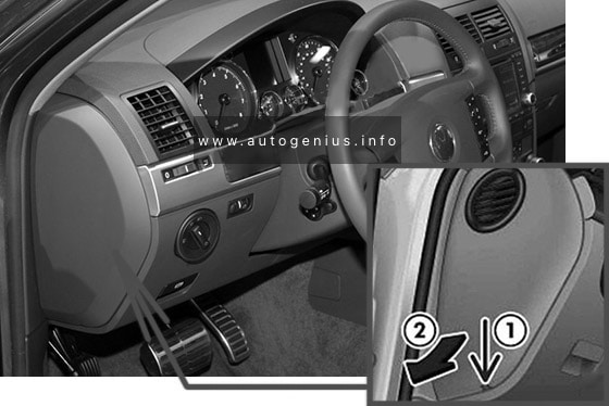
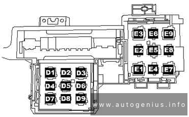
Luggage compartment fuse box
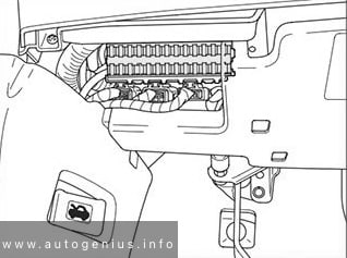
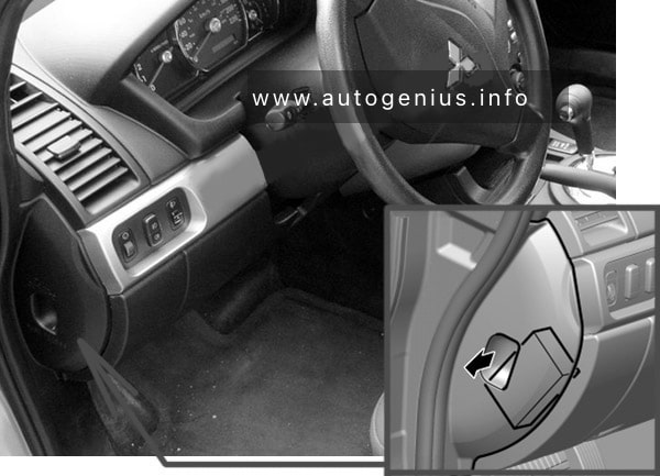
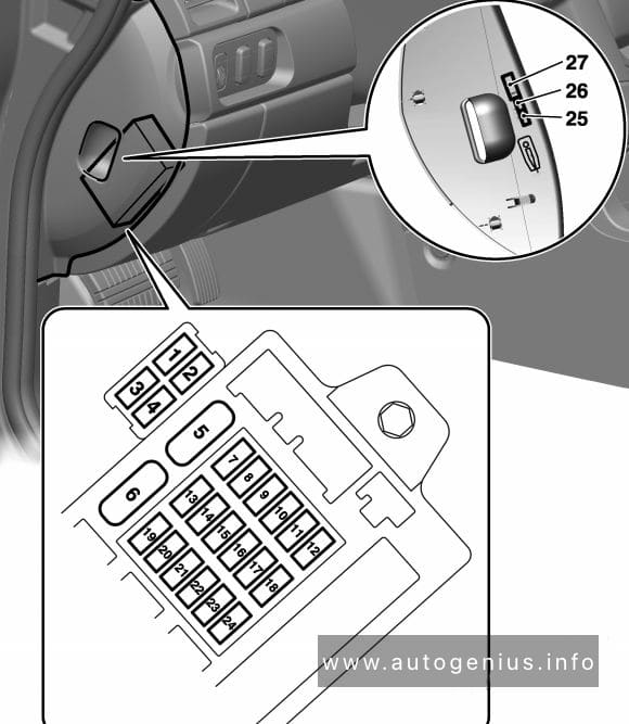
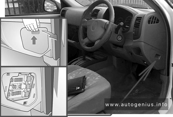
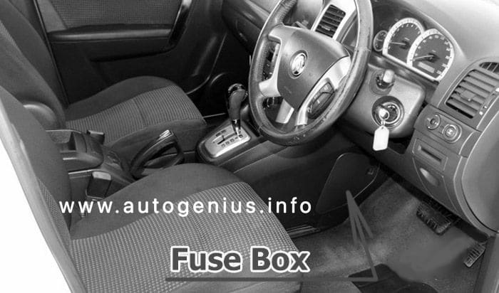
Fuse Box Location
Located behind the left-hand side trim.
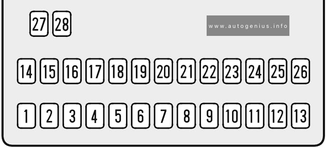
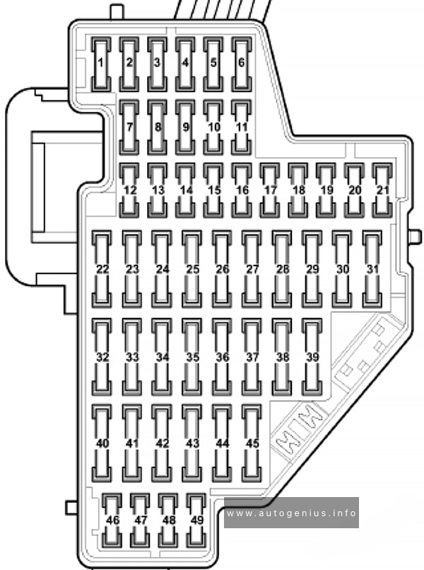
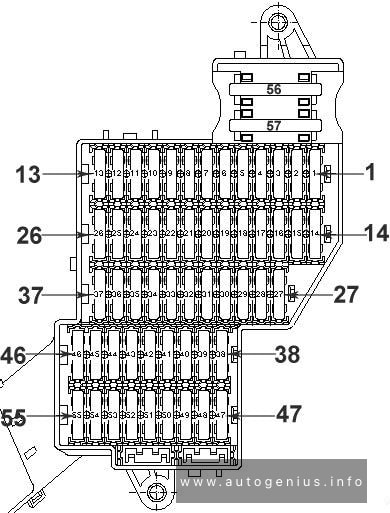
Type 1
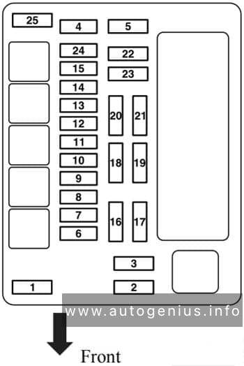
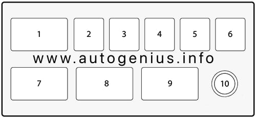
Fuse Box Diagram

Assignment of the fuses in the luggage compartment (type 1)
| № | Amp | Description |
|---|---|---|
| 1 | 25A/30A | Front power windows |
| 2 | — | Not Used |
| 3 | 7.5A | Instrument panel |
| 4 | 5A | Heating / Air Conditioning / Climate Control (HVAC) |
| 5 | 7.5A | Airbag |
| 6 | — | Not Used |
| 7 | — | Not Used |
| 8 | — | Not Used |
| 9 | — | Not Used |
| 10 | — | Not Used |
| 11 | 25A | Rear window heating (rear window glass) |
| 12 | 15A | Windshield wiper of a window of a door of a back |
| 13 | 5A | Parking aid |
| 14 | 7.5A | Air Conditioning System |
| 15 | — | Not Used |
| 16 | 5A | Right front seat occupancy sensor, Open&Start system |
| 17 | 5A | Rain Sensor / Air Quality Sensor / Tire Pressure Monitoring System / Interior Rearview Mirror |
| 18 | 5A | Instruments / switches |
| 19 | — | Not Used |
| 20 | 10A | Damping Dynamic Control System (CDC) |
| 21 | 7.5A | External rear-view mirrors heater |
| 22 | 20A/25A | Sliding roof |
| 23 | 25A/30A | Rear power windows |
| 24 | 7.5A | Diagnostic Connector |
| 25 | — | Not Used |
| 26 | 7.5A | Folding exterior mirrors |
| 27 | 5A | Ultrasonic sensor, anti-theft alarm system |
| 28 | — | Not Used |
| 29 | 15A | Cigar lighter / Front power outlet |
| 30 | 10A/15A | Rear socket for connecting additional electrical appliances |
| 31 | — | Not Used |
| 32 | — | Open & Start system |
| 33 | 15A | Open&Start system |
| 34 | 25A | Sliding roof |
| 35 | 10A/15A | Rear socket for connecting additional electrical appliances |
| 36 | 20A | Towbar socket |
| 37 | 5A | Interior lighting |
| 38 | 25A/30A | Central lock, Output “30” |
| 39 | 15A | Front left seat heater |
| 40 | 15A | Front right seat heater |
| 41 | — | Not Used |
| 42 | — | Not Used |
| 43 | — | Not Used |
| 44 | — | Not Used |
| RELAYS | ||
| К2 | (K3_X131) Relay | Heated rear window, mirrors (on FR11, FR21), (from FB5, FB6) |
| К3 | (K1_X131) Relay | Pin 15 (on FR12, FR13, FR14, FR16, FR17, FR18, FR20) |
| К4 | (K2_X131) Relay | Terminal 15a (on FR39, FR40) |
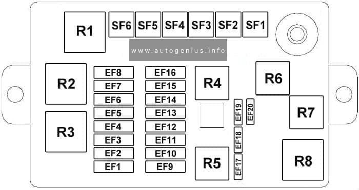
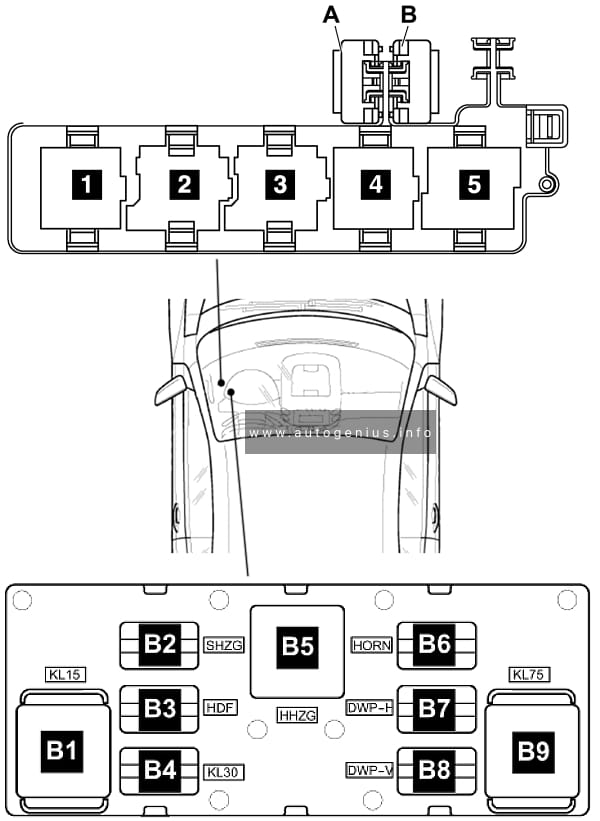
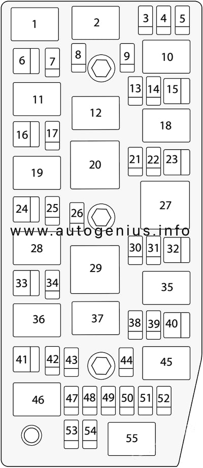
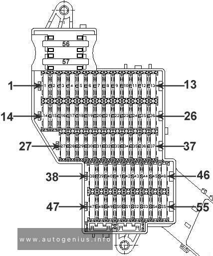
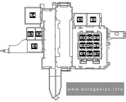
Type 2
Fuse Box Diagram
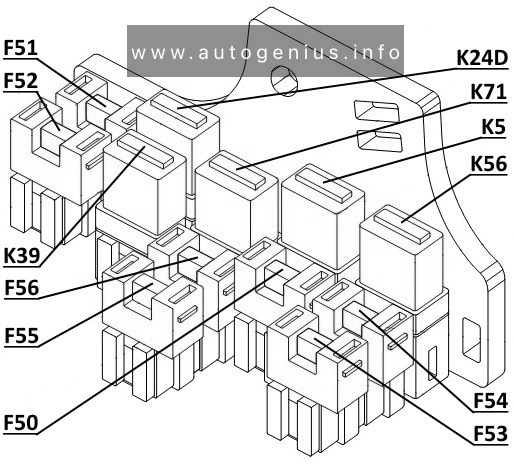
Assignment of the relays in the engine compartment (type 2)
| № | Amp | Description |
|---|---|---|
| F50 | 10A | AC air conditioner (on relay K5) |
| F51 | 15 | Fog lights (front) (on relay K39) |
| F52 | 15 | Auxiliary socket (rear cigarette lighter) ACS |
| F53 | 7.5A | Heated mirrors |
| F54 | 30A | Front windows FHF |
| F55 | 30A | Rear windows FHR |
| F56 | 7,5A | Taillights (on K71), Lock without handle (on K24D) |
| K5 | RELAY | Relay – compressor, air conditioning (FE33, F50) |
| K24D | RELAY | Dead block relay (F56) |
| K39 | RELAY | Relay – fog lamp, front (F51) |
| K56 | RELAY | Relay – wiper, rear window (FE31, FE33) |
| K71 | RELAY | Relay – reversing light (F56, FE33) |
WARNING: Terminal and harness assignments for individual connectors will vary depending on vehicle equipment level, model, and market.