Seat Alhambra (MK2/7N; 2010 – 2020) – fuse and relay box diagram
Year of production: 2010, 2011, 2012, 2013, 2014, 2015, 2016, 2017, 2018, 2019, 2020
This article covers the second-generation SEAT Alhambra (7N), produced from 2010 to 2020. It includes fuse box diagrams for the 2010–2020 models, provides details on the locations of the fuse panels within the vehicle, and explains the function of each fuse (fuse layout) and relay.
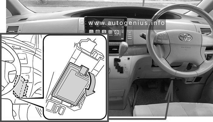
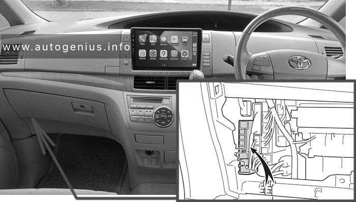
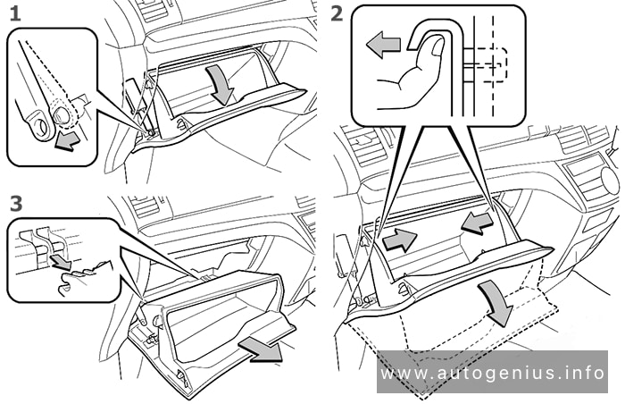
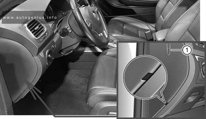
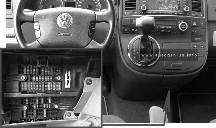
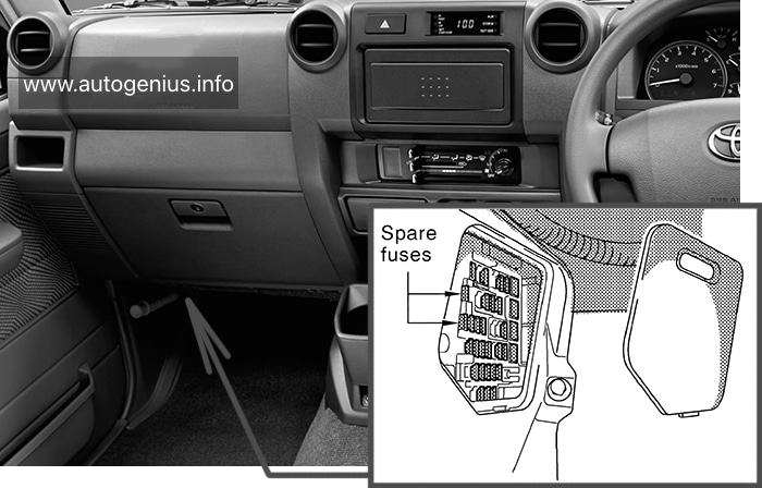
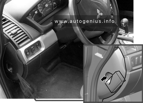
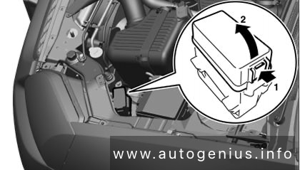
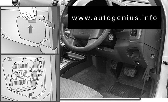
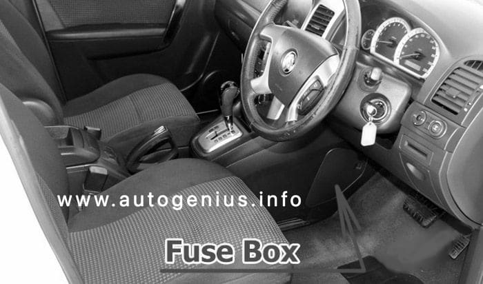
Passenger compartment fuse box
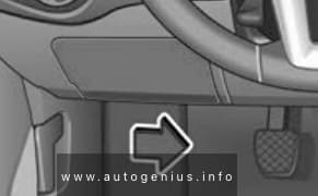
Fuse Box Location
To remove the cover, move the activation lever in the lower part to the right. For right-hand drive vehicles, move the lever to the left.
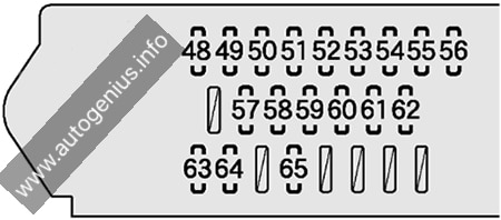
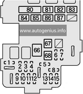
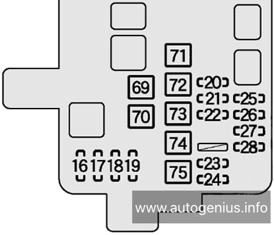
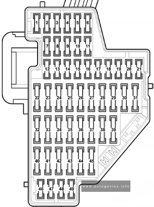
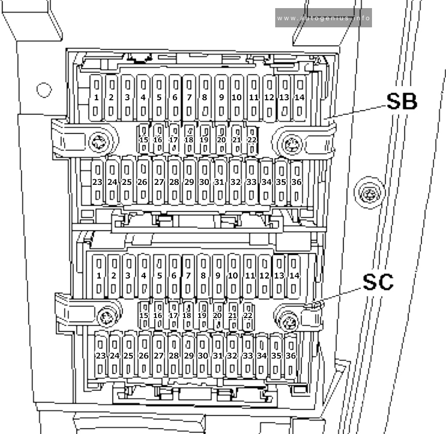
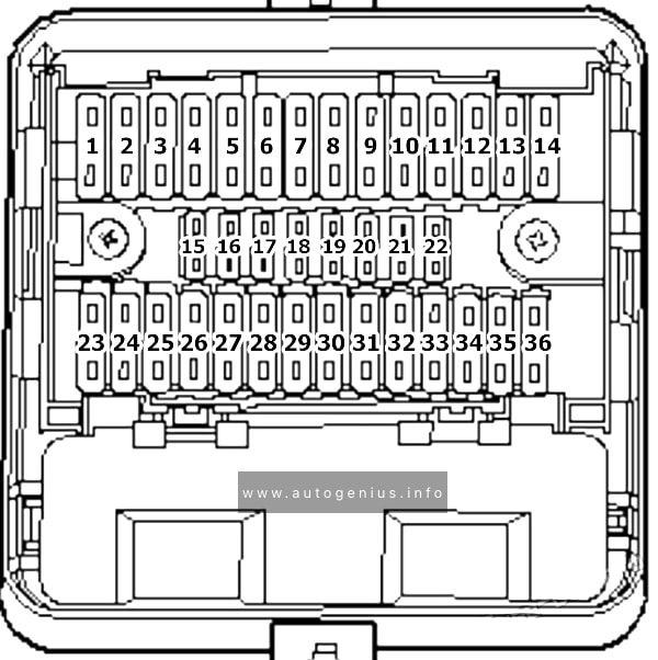
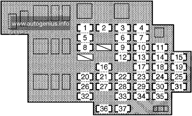
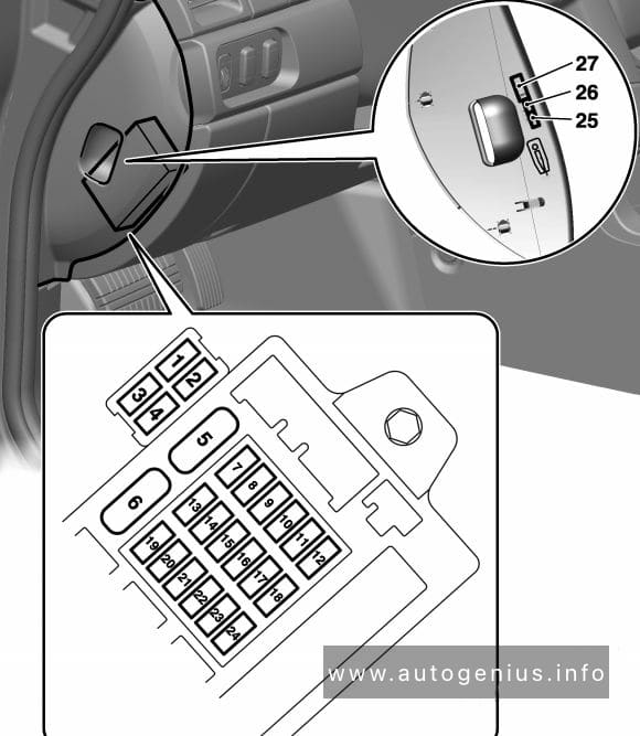
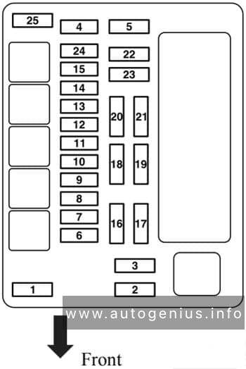
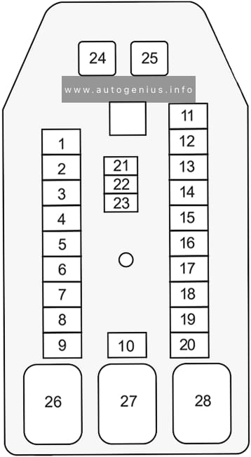
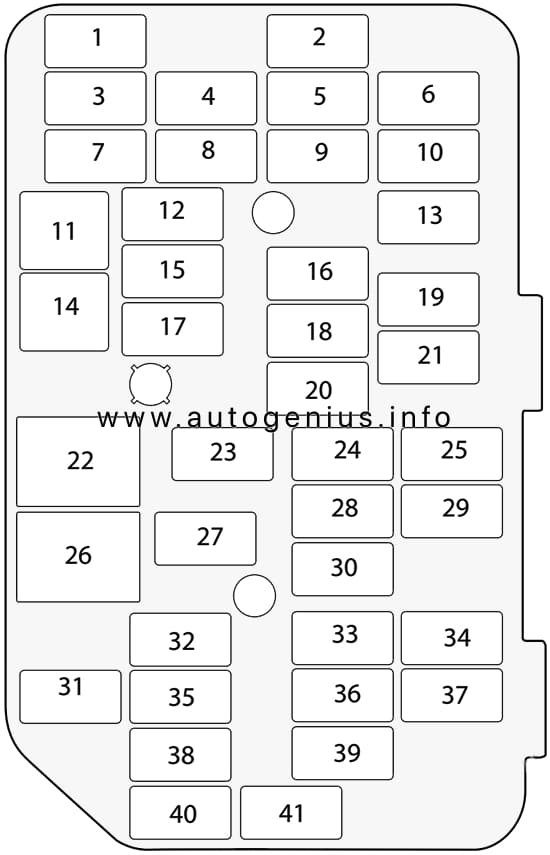
Fuse Box Diagram (-SC-)
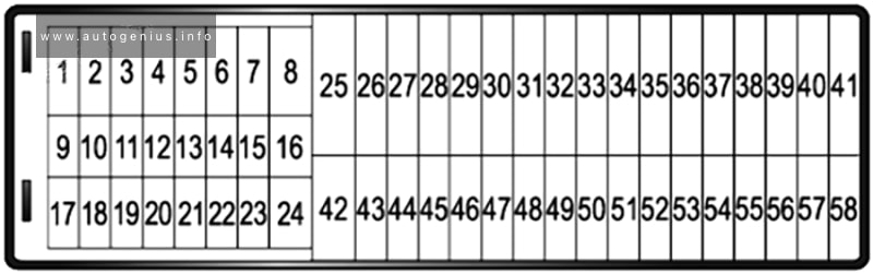
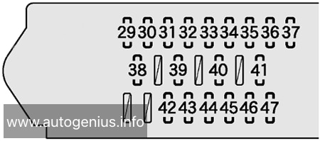
Assignment of the fuses in the instrument panel (Fuse holder C)
| № | Amps | Function/component |
|---|---|---|
| 1 | – | not assigned |
| 2 | 7.5A | 2018-2020: USB connection 1 |
| 3 | 7.5A | 2016-2020: Left washer jet heater element Right washer jet heater element |
| 4 | 10A | DC/AC converter with socket, 12V – 230V Voltage stabiliser Starter relay 1 (with start-stop) Starter relay 2 (with start-stop) |
| 5 | 10A | Electronically controlled damping control unit |
| 6 | 10A | 2015-2020: Blind Spot Monitor control unit Blind Spot Monitor control unit 2 |
| 7 | – | not assigned |
| 8 | – | not assigned |
| 9 | 7.5A | Warning lamp for airbag deactivated on front passenger side Airbag control unit |
| 10 | 5A | 2013-2020 (taxi): Taximeter Mirror taximeter Voltage stabiliser Taxi alarm remote control, control unit |
| 11 | 10A | All-wheel drive control unit |
| 12 | 10A | Left gas discharge (xenon) bulb |
| 13 | 5A | 2010-2015: Electromechanical parking brake button Oil level and oil temperature sender Reversing light switch Operating unit in front of centre console High-pressure sender Parking aid control unit Interior mirror Front camera for driver assist systems |
| 13 | 5A | 2015-2020: Operating unit in front of centre console Reversing light switch High-pressure sender Trailer detector control unit Air quality sensor Adaptive cruise control unit Parking aid control unit Park assist steering control unit Front camera for driver assist systems Automatic anti-dazzle interior mirror |
| 14 | 7.5A | 2010-2015: Light switch Trailer detector control unit Control unit for electromechanical parking brake ABS control unit Brake light switch Power steering control unit Engine/motor control unit Data bus diagnostic interface Control unit in dash panel insert |
| 14 | 7.5A | 2015-2016: Light switch ABS control unit Control unit in dash panel insert Trailer detector control unit Power steering control unit Data bus diagnostic interface Engine/motor control unit |
| 14 | 7.5A | 2016-2020: Light switch ABS control unit Control unit in dash panel insert Operating unit in front of centre console Power steering control unit Switch module 2 in centre console Data bus diagnostic interface Engine/motor control unit Electromechanical parking brake button Oil level and oil temperature sender |
| 15 | 10A | 2010-2015: Auxiliary heater operation relay Diagnostic connection Front left headlight, not xenon Front right headlight, not xenon Control unit for cornering light and headlight range control Switch and instrument illumination regulator Ar mass meter |
| 15 | 10A | 2015-2020: Switch and instrument illumination regulator Control unit for cornering light and headlight range control Front left headlight, not xenon Front right headlight, not xenon Diagnostic connection |
| 16 | 10A | Right gas discharge (xenon) bulb |
| 17 | 5A | 2010-2015: Mobile telephone operating electronics control unit Emergency call module control unit and communication unit |
| 17 | 5A | 2015-2020: Emergency call module control unit and communication unit (LHD) |
| 18 | 7.5A | 2010-2015: Taxi alarm remote control, control unit Data transmission control unit |
| 19 | – | not assigned |
| 20 | 5A | ABS control unit |
| 21 | 5A | 2010-2016: 2nd heat exchanger switch-off valve |
| 21 | 5A | 2016-2020: Electromechanical parking brake button Selector lever |
| 22 | 7.5A | Light switch Rain and light sensor Reversing camera system control unit Diagnostic connection |
| 23 | 7.5A | 2010-2015: Selector lever sensors control unit Electromechanical parking brake button Climatronic control unit Air conditioning system control unit Operating and display unit for rear air conditioning system Rear blower regulation sender Remote control receiver for auxiliary coolant heater |
| 23 | 7.5A | 2015-2020: Operating and display unit for rear air conditioning system Rear blower regulation sender Climatronic control unit Remote control receiver for auxiliary coolant heater 2nd heat exchanger switch-off valve (2016-2020) |
| 24 | 7.5A | Entry and start authorisation control unit |
| 25 | 7.5A | Selector lever Mechatronic unit for dual clutch gearbox |
| 26 | 5A | 2010-2016: Air quality sensor |
| 27 | – | not assigned |
| 28 | 15A | Rear window wiper motor |
| 29 | 30A | 2010-2015: 12V socket 12V socket 3 Blocking diode |
| 29 | 20A | 2015-2020: Blocking diode Cigarette lighter 12V socket 12V socket 2 12V socket 3 Onboard supply control unit (T52c/21) Terminal 75 diagnosis feedback |
| 30 | 30A | 2010-2015: Cigarette lighter 12V socket 2 Onboard supply control unit (T52c/21) Terminal 75 diagnosis feedback |
| 30 | 20A | 2015: Cigarette lighter 12V socket 2 |
| 30 | 30A | 2015-2020: Blower relay |
| 31 | – | not assigned |
| 32 | – | not assigned |
| 33 | – | not assigned |
| 34 | – | not assigned |
| 35 | – | not assigned |
| 36 | 30A | 2010-2015: Control unit for electromechanical parking brake |
| 36 | 5A | 2015-2016: Two-way signal amplifier for mobile telephone/data services Storage compartment with interface for mobile telephone |
| 36 | 20A | 2016-2020: Control unit 1 for information electronics |
| 36 | 30A | 2020: Right sliding door control unit |
| 37 | 10A/25A | 2010-2011: Two-way radio or Sliding sunroof adjustment control unit |
| 37 | 25A | 2011-2020: Sliding sunroof adjustment control unit |
| 38 | 10A/30A | 2010-2011: Taximeter Interior light switch Taxi sign switch Taxi alarm active button Mirror taximeter Front interior light button or Sunroof roller blind control unit |
| 38 | 30A | 2011-2020: Sunroof roller blind control unit |
| 39 | 5A/7.5A | Steering column electronics control unit |
| 40 | 5A | 2010-2015: Multimedia system control unit |
| 40 | 5A | 2016-2020: Two-way signal amplifier for mobile telephone/data services Storage compartment with interface for mobile telephone |
| 41 | 5A | Dash panel insert |
| 42 | 15A | Electronically controlled damping control unit |
| 43 | 30A | 2010-2017: Driver seat lumbar support adjistment switch Front passenger seat lumbar support adjistment switch |
| 44 | 25A/30A | Fresh air blower relay (LHD) Heated rear window relay |
| 45 | 30A | Front passenger door control unit Rear right door control unit |
| 46 | 30A | Driver door control unit Rear left door control unit |
| 47 | 10A | 2011-2020 (taxi): Interior light switch Taxi sign switch Taxi alarm active button Mirror taximeter (2011-2015) Front interior light button (2013-2015) |
| 48 | 15A | Alarm horn Interior monitoring sensor Onboard supply control unit (T52c/1) Terminal 30, Anti-theft alarm supply |
| 49 | 30A | 2010-2015: Control unit for electromechanical parking brake |
| 49 | 7.5A | 2015-2020: Relay for reducing agent metering system (diesel) Delivery unit for reducing agent metering system (diesel) |
| 50 | 30A | Onboard supply control unit (T52b/1) Terminal 30, central locking supply |
| 51 | 30A | Heated front seats control unit |
| 52 | 20A | 2010-2011: Headlight washer system relay Headlight washer system pump |
| 52 | 30A | 2011-2020: Rear fresh air blower |
| 53 | 30A | DC/AC converter with socket, 12V – 230V |
| 54 | 5A/10A | Control unit for electronic steering column lock |
| 55 | 25A | 2010-2013: Trailer voltage supply control unit |
| 55 | 20A | 2013-2020: All-wheel drive control unit |
| 56 | 30A | 2010-2013: Trailer detector control unit |
| 56 | 30A | 2015-2020: Control unit for reducing agent metering system (diesel) |
| 57 | 10A | 2011-2015: Two-way radio |
| 58 | 25A | 2010-2015: Special vehicle control unit |
| 58 | 30A | 2015-2020 (taxi): Voltage stabiliser |
| 58 | 20A | 2020: Control unit 1 for information electronics (RHD) |
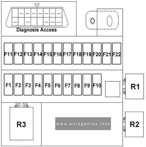
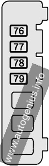
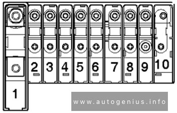
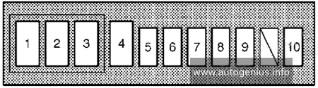
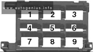
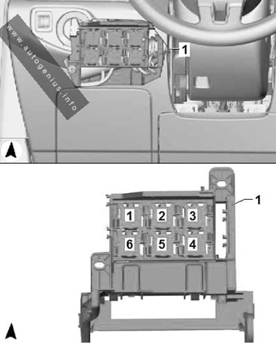
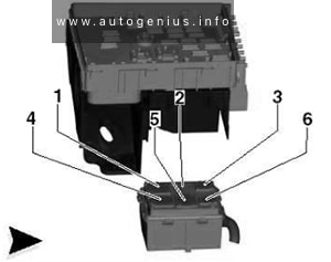
Individual fuses (SR1)
Assignment of the fuses in the instrument panel (Individual fuses (SR1))
| № | Amps | Function/component |
|---|---|---|
| 1 | 40A | Right sliding door control unit |
| 2 | 20A/30A | Driver seat adjustment operating unit Driver seat adjustment control unit Driver seat backrest adjustment switch Driver seat lumbar support adjustment switch |
| 3 | 20A/30A | Front passenger seat adjustment operating unit Front passenger seat backrest adjustment switch Front passenger seat lumbar support adjustment switch |
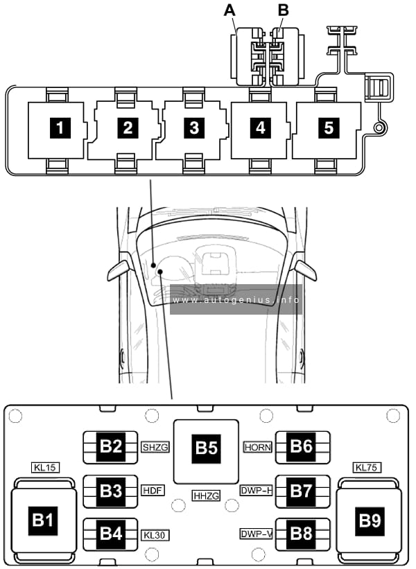
Relay carrier #1 (on left behind dash panel)
2010-2015
Assignment of the fuses in the instrument panel (Relay carrier #1)
| № | Relay |
|---|---|
| 1 | Terminal 50 voltage supply relay (without start/stop) |
| 2 | Heated rear window relay |
| 3 | Auxiliary heater operation relay (with auxiliary heater, LHD) Low heat output relay (with auxiliary heater) |
| 4 | not assigned |
| 5 | not assigned |
| 6 | Fresh air blower relay (with auxiliary heater) |
| 7 | 2010-2012: Additional coolant pump relay (petrol) |
| 8 | 2010-2012: Dual tone horn relay |
| 9 | 2010-2012: Headlight washer system relay |
2016-2020
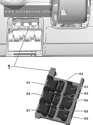
Assignment of the fuses in the instrument panel (Relay carrier #1)
| № | Relay |
|---|---|
| R1 | not assigned |
| R2 | not assigned |
| R3 | not assigned |
| R4 | not assigned |
| R5 | Blower relay |
| R6 | Heated rear window relay |
| R7 | not assigned |
| R8 | Fresh air blower relay (LHD) |
| R9 | Low heat output relay Auxiliary heater operation relay (LHD) |
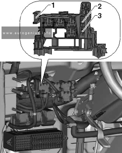
Relay carrier #2 (SR1, on left under dash panel)
Assignment of the fuses in the instrument panel (Relay carrier #2)
| № | Relay |
|---|---|
| 1 | 2010-2016: High heat output relay (LHD) 2016-2020: Terminal 15 voltage supply relay 2 |
| 2 | Terminal 75 voltage supply relay 1 |
| 3 | 2010-2016: Terminal 15 voltage supply relay 2 2016-2020: High heat output relay (LHD) |
| 4 | Heated windscreen relay |
| 5 | High heat output relay (RHD) |
| 6 | not assigned |
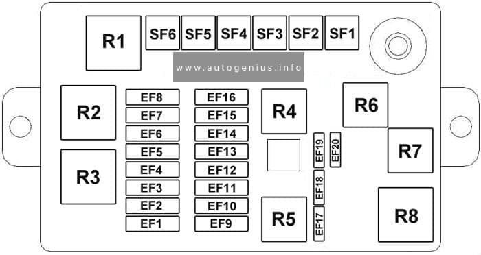
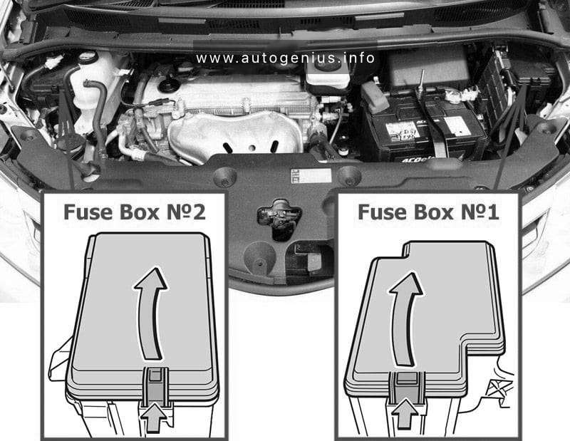
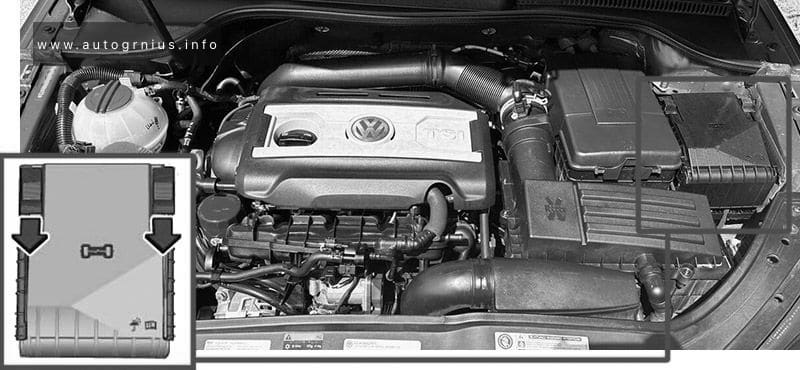
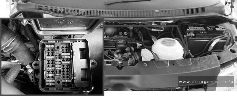
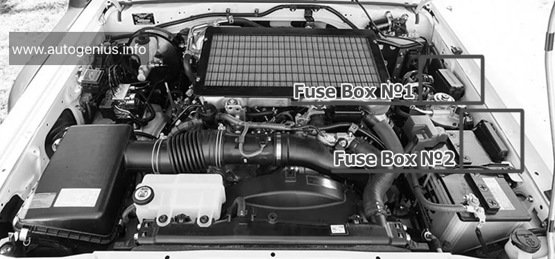
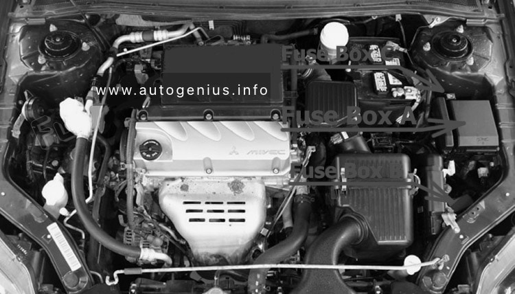
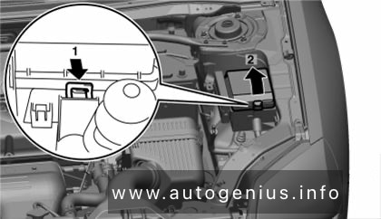
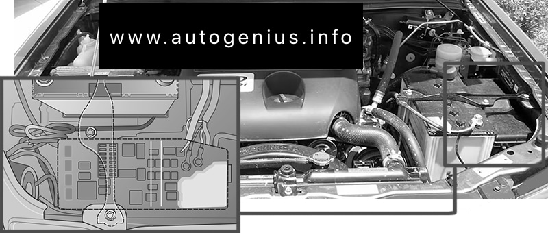
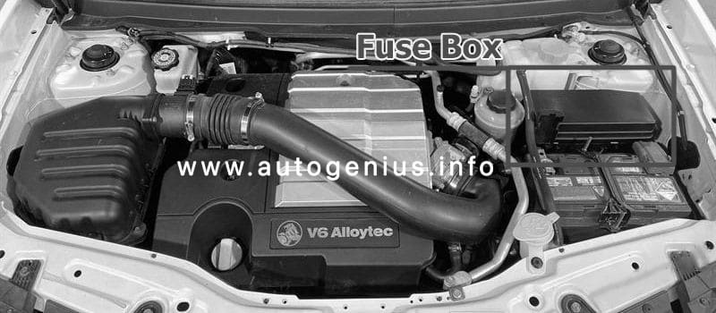
Engine compartment fuse box
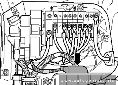
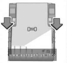
Fuse Box Location
Move the attachment tabs forwards, in the direction indicated by the arrow to release the fuse box cover. Then lift the cover out.
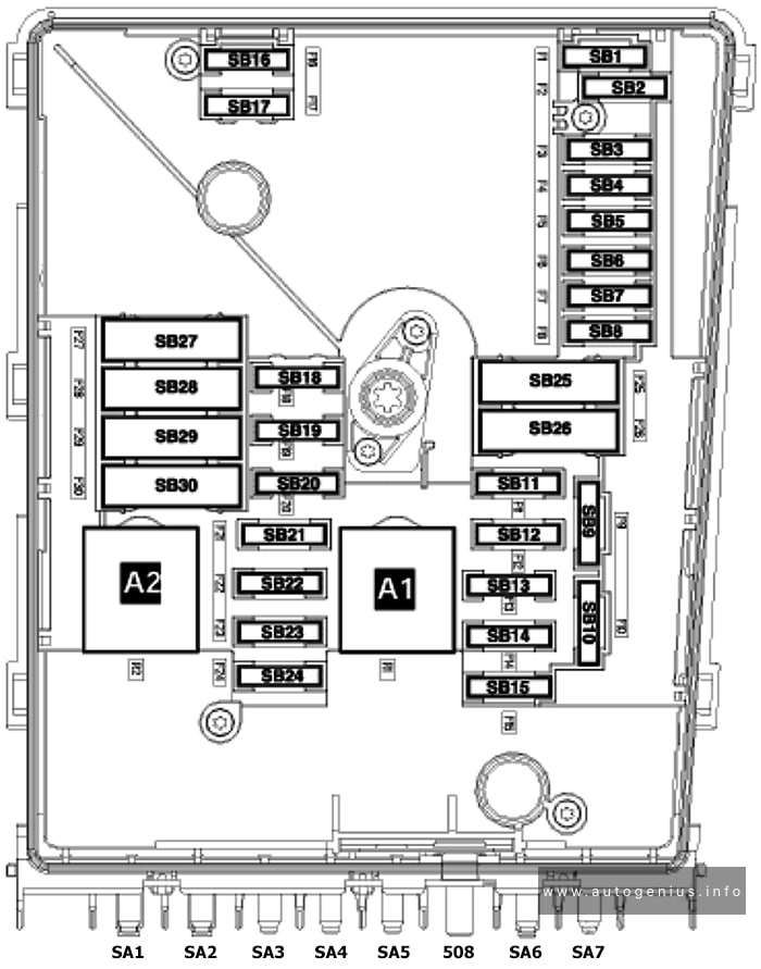
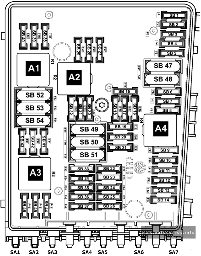
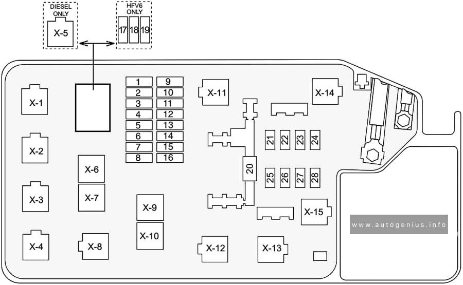
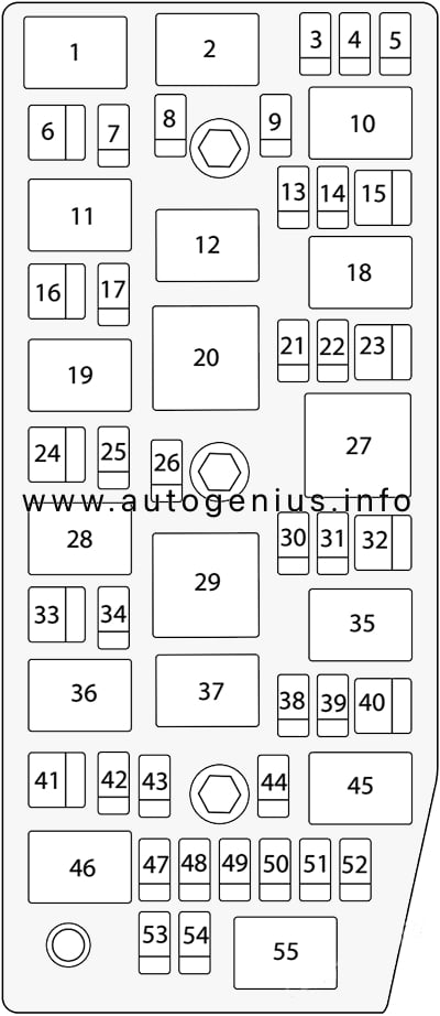
Fuse Box Diagram (-SA-)
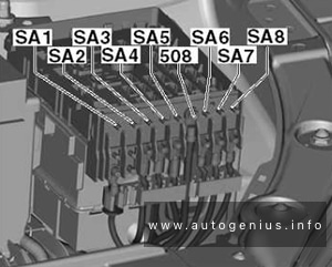
Assignment of the fuses in the engine compartment (holder A)
| № | Amps | Function/component |
|---|---|---|
| SA1 | 150A/200A/400A | Alternator |
| SA2 | 80A | Power steering control unit |
| SA3 | 80A | Radiator fan control unit |
| SA4 | 80A | Fuse holder D -SD- |
| SA5 | 100A | Fuse holder C -SC- 20-pin jumper |
| 508 | Terminal 30 wiring junction | |
| SA6 | 50A | Heated windscreen relay |
| SA7 | 70A | High heat output relay |
| SA8 | 60A | Thermal fuse 2 – rear right sliding door Driver seat adjustment thermal fuse 1 Front passenger seat adjustment thermal fuse 1 |
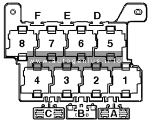
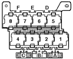
Fuse Box Diagram (-SB-)
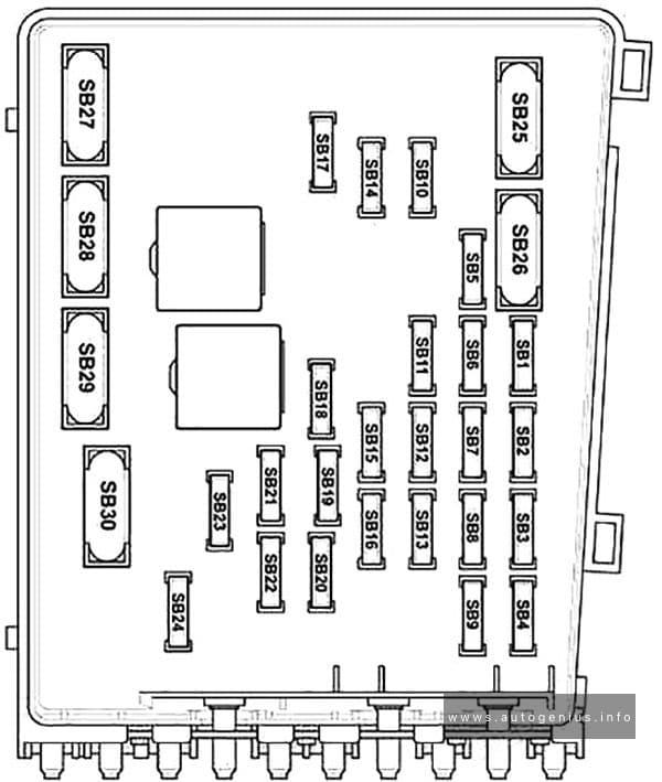
Assignment of the fuses in the engine compartment (Fuse holder B)
| № | Amps | Function/component |
|---|---|---|
| F1 | 30A | 2010-2016: Voltage stabiliser |
| F1 | 20A | 2016-2020: Control unit 1 for information electronics Display unit for front information display and operating unit control unit |
| F2 | 30A | Onboard supply control unit (T52b/42) Terminal 30 power |
| F3 | 30A | 2010-2016: ABS control unit Wiper motor control unit |
| F3 | 30A | 2016-2017: Wiper motor control unit |
| F3 | 20A/30A | 2017-2020: Headlight washer system relay Headlight washer system pump |
| F4 | 30A | Onboard supply control unit (T52a/1) terminal 30, left light supply |
| F5 | 5A | Onboard supply control unit (T52a/24) terminal 30, reference Battery monitor control unit |
| F6 | 30A | Onboard supply control unit (T52c/42) terminal 30, right light supply |
| F7 | 25A | Dual tone horn relay Heated windscreen relay |
| F8 | 30A | Digital sound package amplifier |
| F9 | 20A | 2010-2015: Control unit with display for radio and navigation |
| F9 | 15A | 2018-2020: Additional coolant pump relay (petrol) Vacuum pump for brakes (petrol) Brake servo pressure sensor |
| F10 | 30A | Engine/motor control unit |
| F11 | 5A | Data bus diagnostic interface |
| F12 | 15A | Mechatronic unit for dual clutch gearbox |
| F13 | 5A | Engine/motor control unit Main relay Fuse 10 on fuse holder B Fuse 14 on fuse holder B Fuse 16 on fuse holder B Fuse 18 on fuse holder B Fuse 20 on fuse holder B Fuse 23 on fuse holder B Fuse 24 on fuse holder B |
| F14 | 30A/15A/10A | 2010-2015: Pump for reducing agent (diesel) Ignition coil 1~4 with output stage |
| F14 | 15A/30A | 2015-2020: Ignition coil 1~4 with output stage Coolant shut-off valve Coolant valve for gearbox |
| F14 | 30A | 2020: Ignition coil 1~4 with output stage |
| F15 | – | not assigned |
| F16 | 15A/30A | 2010-2015: Control unit for reducing-agent heater (diesel) Lambda probe Lambda probe after catalytic converter Magnetic clutch for supercharger |
| F16 | 15A/30A | 2015-2016: Lambda probe 1 after catalytic converter (petrol) Lambda probe 1 before catalytic converter (petrol) Activated charcoal filter solenoid valve 1 (petrol) Camshaft control valve 1 (2016) |
| F16 | 15A | 2016-2020: Lambda probe 1 after catalytic converter (petrol) Lambda probe 1 before catalytic converter (petrol) Activated charcoal filter solenoid valve 1 (petrol) Camshaft control valve 1 Fuel pressure regulating valve (diesel) Fuel metering valve (diesel) Exhaust camshaft control valve 1 (petrol) Coolant circulation pump 2 (petrol) |
| F17 | 15A/20A | 2010-2015: Fuel pressure regulating valve |
| F17 | 15A | 2015-2016: Camshaft control valve 1 (2015) Fuel pressure regulating valve (diesel) Fuel metering valve (diesel) Exhaust camshaft control valve 1 (petrol) Coolant circulation pump 2 (petrol) Ignition coil 1~4 with output stage (petrol) |
| F17 | 20A | 2016-2020: Ignition coil 1~4 with output stage (petrol) |
| F18 | 30A | Fuel pump control unit |
| F19 | 30A | 2010-2015: Wiper motor control unit |
| F19 | 40A | 2015-2020: ABS control unit |
| F20 | 15A | 2010-2015: Additional coolant pump relay (petrol) Lambda probe (diesel) Control unit for NOx sender (diesel) Air mass meter(diesel) |
| F20 | 5A | 2015-2020: Brake light switch Clutch position sender Additional coolant pump relay (2015-2016) |
| F21 | 20A | Auxiliary heater control unit |
| F22 | 30A | 2010: Rear fresh air blower |
| F22 | 20A | 2011-2017: Headlight washer system relay Headlight washer system pump |
| F22 | 20A | 2017-2020: Wiper motor control unit |
| F23 | 15A | 2010-2015: Charge pressure control solenoid valve (diesel) Heater element for crankcase breather (diesel) Automatic glow period control unit (diesel) Exhaust gas recirculation cooler changeover valve (diesel) Fuel metering valve (diesel) Fuel pressure regulating valve (diesel) Coolant circulation pump 2 (diesel) Additional coolant pump relay (petrol) Clutch position sender Brake light switch (2011) |
| F23 | 10A/15A | 2015-2020: Brake light switch (petrol) Air mass meter (diesel) Additional coolant pump relay (petrol) Coolant circulation pump (petrol) Charge pressure control solenoid valve (diesel) Heater element for crankcase breather (diesel) Turbocharger air recirculation valve (diesel) Intake manifold flap valve (petrol) Valve for oil pressure control Coolant valve for cylinder head (diesel) Piston cooling jet control valve (petrol) Charge air cooling pump Auxiliary pump for heating (diesel) |
| F23 | 10A/15A | 2020: Brake light switch (petrol) Air mass meter (diesel) Additional coolant pump relay (petrol) Coolant circulation pump (petrol) Charge pressure control solenoid valve (diesel) Heater element for crankcase breather (diesel) Coolant valve for cylinder head (diesel) Charge air cooling pump Auxiliary pump for heating (diesel) |
| F24 | 10A | 2010-2015: Engine component current supply relay Fuse 17 on fuse holder B (petrol) Fuse 28 on fuse holder B (diesel) Radiator fan control unit Turbocharger air recirculation valve Activated charcoal filter solenoid valve 1 Camshaft control valve 1 Charge pressure control solenoid valve (petrol) Low heat output relay High heat output relay |
| F24 | 10A/20A | 2015-2020: Engine component current supply relay Fuse 17 on fuse holder B (petrol) Fuse 28 on fuse holder B (diesel) Lambda probe 1 before catalytic converter (diesel) Radiator fan control unit Low heat output relay High heat output relay Relay for reducing agent metering system (diesel) Activated charcoal filter solenoid valve 1 (petrol) Camshaft control valve 1(petrol) Exhaust camshaft control valve 1 (petrol) Valve for oil pressure control (petrol) Injector 2 for cylinder 1~4 (petrol) Exhaust cam actuator A for cylinder 1~4 (petrol) Exhaust cam actuator B for cylinder 1~4 (petrol) Additional coolant pump relay (petrol) (2018-2020) |
| F24 | 15A | 2020: Engine component current supply relay Fuse 17 on fuse holder B (petrol) Fuse 28 on fuse holder B (diesel) Lambda probe 1 before catalytic converter (diesel) Radiator fan control unit Control unit for NOx sender (diesel) Relay for reducing agent metering system Activated charcoal filter solenoid valve 1 (petrol) Camshaft control valve 1 (petrol) Exhaust camshaft control valve 1 (petrol) Valve for oil pressure control (petrol) Additional coolant pump relay (petrol) |
| F25 | 40A | ABS control unit |
| F26 | 40A | Fresh air blower control unit Low heat output relay |
| F27 | 50A | Terminal 15 voltage supply relay 2 |
| F28 | 50A | Automatic glow period control unit (diesel) |
| F29 | 40A/50A | Fuse 17 on fuse holder C Fuse 18 on fuse holder C (2010-2015) Fuse 36 on fuse holder C Fuse 37 on fuse holder C Fuse 38 on fuse holder C Fuse 39 on fuse holder C Fuse 40 on fuse holder C Fuse 41 on fuse holder C Fuse 58 on fuse holder C |
| F30 | 50A | Terminal 75 voltage supply relay 1 |
| R1 | CCZA engine: Engine component current supply relay Diesel: Connection bridge |
|
| R2 | Petrol: Main relay Diesel: Terminal 30 voltage supply relay |
Relays under E-box low
Assignment of the fuses in the engine compartment (Relays under E-box low)
| № | Relay |
|---|---|
| 1 | With start/stop: Starter relay 1 |
| 2 | Diesel: Automatic glow period control unit |
| 3 | 2012-2020: Dual tone horn relay |
| 4 | 2012-2020: Headlight washer system relay |
| 5 | With start/stop: Starter relay 2 (with start/stop) Without start/stop: Terminal 50 voltage supply relay |
| 6 | 2012-2016, 2018-2020: Additional coolant pump relay |
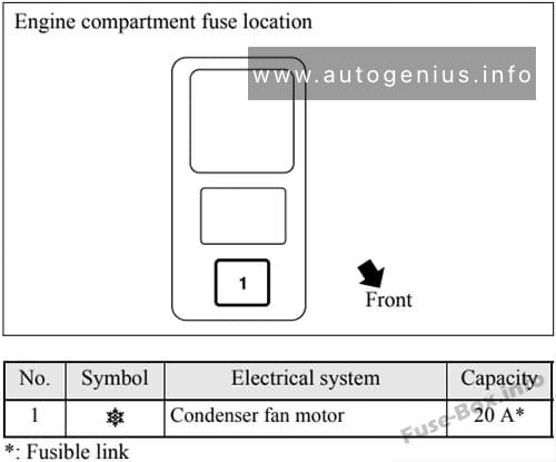
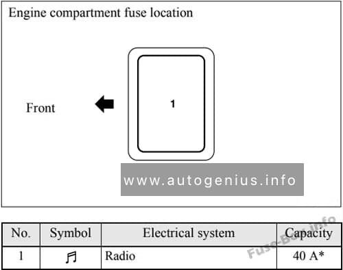
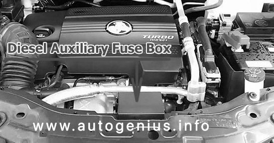
Luggage Compartment Fuse Box
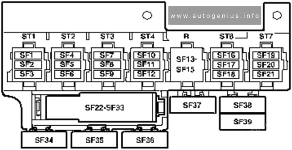
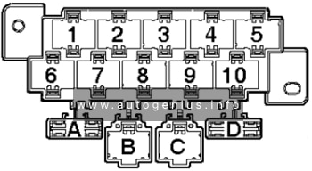
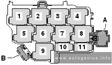
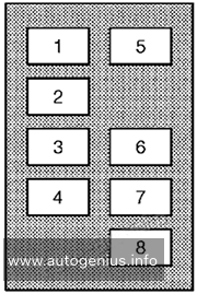
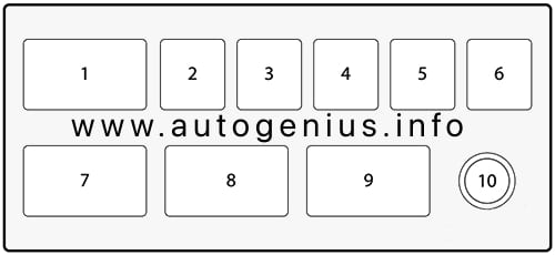
Fuse Box Diagram (Fuse holder D)
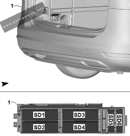
Assignment of the fuses in the engine compartment (Fuse holder D)
| № | Amps | Function/component |
|---|---|---|
| 1 | 40A/30A | Left sliding door control unit |
| 2 | 30A | Rear lid control unit |
| 3 | 30A | Trailer detector control unit |
| 4 | 25A/30A | Trailer detector control unit |
| 5 | 25A/30A | 2013-2020: Trailer voltage supply relay |
| 6 | 30A | 2013-2020: Trailer detector control unit |
Relays
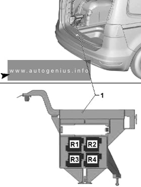
Assignment of the fuses in the engine compartment (Relays)
| № | Relay |
|---|---|
| R1 | Trailer voltage supply relay |
| R2 | Relay for reducing agent metering system |
| R3 | – |
| R4 | – |
| 5 | 2013-2020: Trailer voltage supply relay |
| 6 | 2013-2020: Trailer detector control unit |
WARNING: Terminal and harness assignments for individual connectors will vary depending on vehicle equipment level, model, and market.