This article provides the first-generation Holden Colorado (RC), manufactured between 2008 and 2012. It provides fuse box diagrams for the 2009, 2010, 2011, and 2012 models, along with details on the location of the fuse panels inside the vehicle. Additionally, it explains the function of each fuse (fuse layout) and relay.
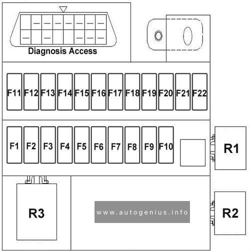
Passenger Compartment Fuse Box
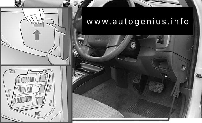
Fuse Box Location
The fuse panel is located on the right-hand side of the dashboard. To open the fuse cover, open the driver’s door, pull the top of the cover out, then pivot downward.
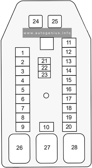
Assignment of the fuses in the passenger compartment
№
Amps
Description
1
10A
Meter
2
–
–
3
10A/15A
Petrol L4: IG coil
HFV6: Engine
Diesel: TCM
4
15A
Back light
5
10A
Turn light
6
10A
Elec. IG
7
10A
Petrol L4: Engine
HFV6: ECU
Diesel: Engine
8
10A
ABS / 4WD
9
20A
Frt wiper
10
10A
SRS
11
10A
Audio
12
20A
Cigar & Acc socket
13
15A
Audio (+B)
14
20A
Door lock
15
10A
Meter (+B)
16
10A
Room light
17
–
–
18
15A
Stop light
19
–
–
20
10A
Starter
21
10A
Spare
22
15A
Spare
23
20A
Spare
24
20A
HFV6, Diesel: RR defog (Slow blow fuse)
25
30A
HFV6, Diesel: Power window (Slow blow fuse)
26
HFV6, Diesel: RR defog relay
27
HFV6, Diesel: Power window relay
28
–
–
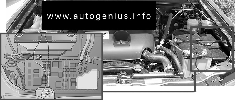
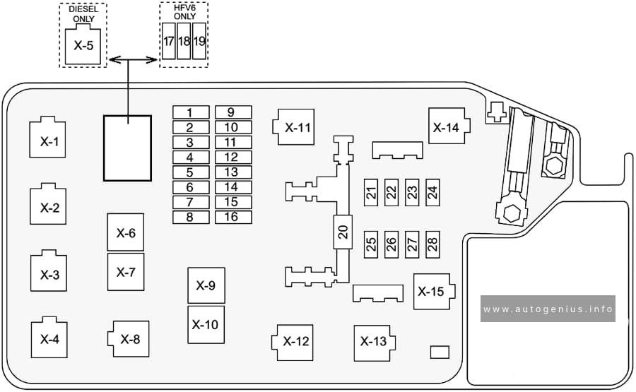
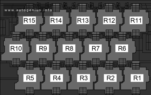
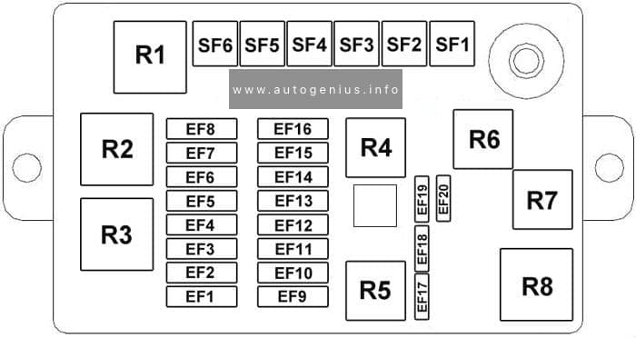
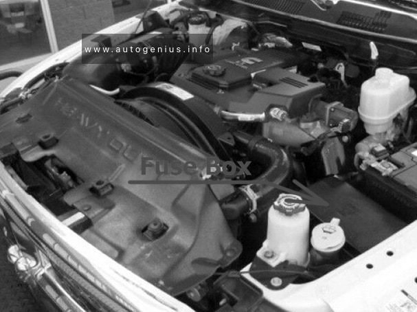
Engine Compartment Fuse Box
Fuse Box Location
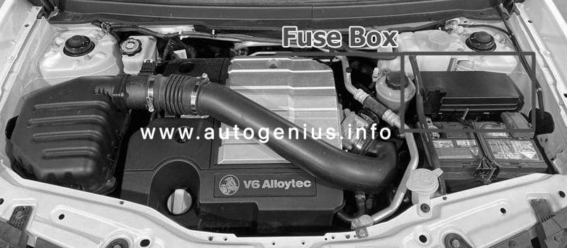
This fuse box is located on the passenger side of the engine compartment. It contains circuit fuses, main fuses and relays. To remove the cover, press the catch on the side of the fuse box toward the engine and release the two tabs at the opposite side.
Year of production: 2011, 2012, 2013, 2014, 2015, 2016
The Holden Captiva 5 (CG-II, facelifted), a compact crossover SUV, was manufactured between 2011 and 2016. This article provides fuse box diagrams for the 2011, 2012, 2013, 2014, 2015, and 2016 models. You’ll also find details about the location of the fuse panels within the vehicle and learn about the fuse and relay assignments (fuse layout).
Passenger Compartment Fuse Box
Fuse Box Location
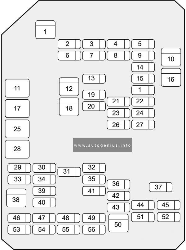
The fuses are located on the left-hand side of the driver’s side footwell. To open the fuse cover, pull the latch rearwards to disengage the cover.
Assignment of the fuses in the passenger compartment
№
Amps
Description
1
30A
DRVR PWR SEAT
2
10A
S/ROOF FOLDING MIRROR
3
20A
FSCM / VENT SOL
4
15A
F/DOOR LOCK
5
20A
DR/LCK
6
20A
TRLR
7
20A
APO JACK (CONSOLE)
8
20A
HTD SEAT PWR / REAR A/C
9
15A
BCM (PRK/TRN)
10
30A
PASS PWR WNDW
11
ACC/RAP RELAY
12
20A
2011-2013: S/ROOF BATT
13
20A
CIGAR
14
15A
BCM (STOP)
15
15A
BCM (CTSY)
16
20A
DRV PWR WNDW
17
CIGAR / APO JACK RELAY
18
20A
2014-2016: S/ROOF BATT
19
20A
APO JACK REAR CARGO
20
15A
RUN/CRANK
21
SPARE
22
30A
AMP (audio system)
23
15A
BCM (TRN SIG)
24
15A
DRL
25
RUN RELAY
26
20A
FRT WSR
27
10A
L/GATE
28
RUN/CRANK RELAY
29
20A
HEATING MAT SW
30
10A
FSCM
31
15A
AWD/VENT
32
15A
2015-2016: RR HEAT SEAT
33
10A
RUN2
34
5A
ISRVM/RCM
35
15A
RR FOG
36
15A
BCM (DIMMER)
37
15A
LOGISTIC MODE
38
40A
HVAC BLWR
39
10A
CLSTR
40
10A
SDM (IGN 1)
41
5A
PWR DIODE
42
10A
2011-2014: XBCM
2015-2016: BCM (VBATT)
43
30A
TRLR BATT
44
15A
RVS / HVAC / DLC
45
2A
PWR / MODING
46
10A
SSPS
47
10A
XBCM
48
20A
BCM (INT LIGHT) / TRLR FOG
49
10A
IPC
50
30A
2015-2016: DC DC CONVERTER
51
10A
SDM (BATT)
52
SPARE
53
2A
OSRVM
54
10A
AUDIO / KEY CAPTURE
55
SPARE
56
2A
STR/WHL SW
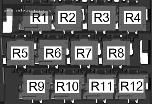
Engine Compartment Fuse Box
Fuse Box Location
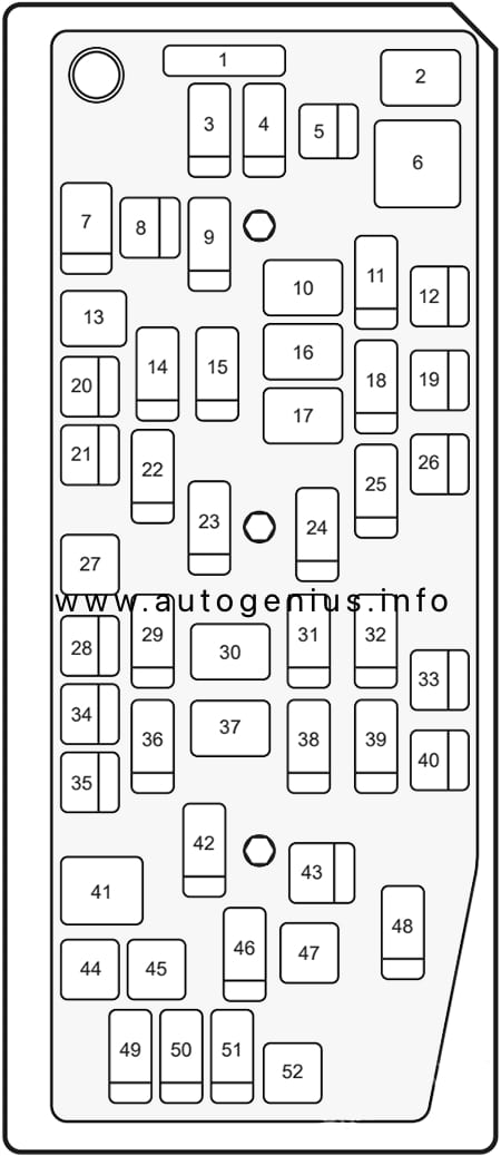
This fuse box is located toward the rear of the engine compartment next to the coolant reservoir, it contains circuit fuses, main fuses and relays. To remove the cover, press the catch on the side of the fuse box toward the engine and release the two tabs at the opposite side.
Year of production: 2010, 2011, 2012, 2013, 2014, 2015, 2016, 2017
This article covers the sixth-generation Volkswagen Jetta (A6, Typ 1B), produced from 2010 to 2017. It provides fuse box diagrams for the 2010, 2011, 2012, 2013, 2014, 2015, 2016, and 2017 models, details the locations of the fuse panels inside the vehicle, and explains the function of each fuse (fuse layout) and relay.
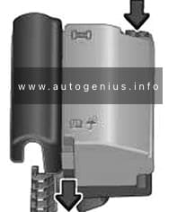
Passenger Compartment Fuse Box
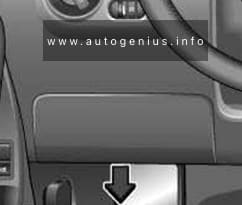
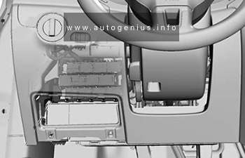
Fuse Box Location
The fuse box is located behind the cover on the driver’s side. Pull the lower part of the cover in the direction of the arrow and remove the cover from the bottom. On the inside of the cover there are plastic tweezers for removing and inserting fuses.
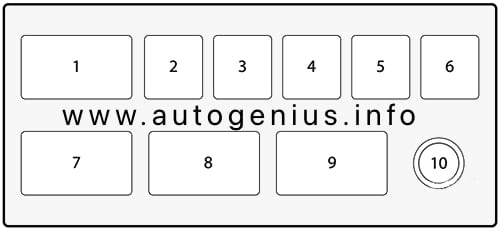
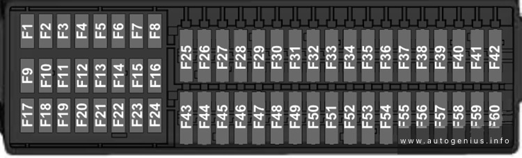
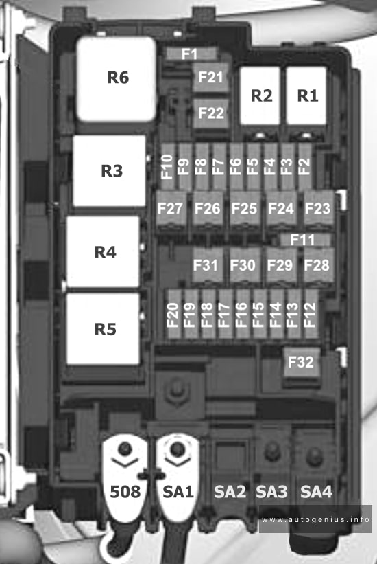
Volkswagen Jetta (A6; 2010 – 2017) – fuse and relay diagram – passenger compartment (holder C)
Assignment of the fuses in the instrument panel (holder C)
№
Amps
Function/Component
F1
10A
2014-2017: Left washer nozzle heater Right washer nozzle heater
F2
5A/7,5A
Electronic steering column lock control module
F3
10A
Instrument cluster control module
F4
2A/10A
2012-2017: Telephone Transceiver Compass magnetic field sensor (vehicles equipped with Start/Stop)
F5
7.5A
2012-2017: Left rear fog lamp bulb
F6
10A
Vehicle electrical system control module (T73a/66) (interior lamp, AW0 only) Rearview camera (2014-2017)
F7
5A
Fog lamp relay (AW0 only) Instrument panel and switch illumination dimmer switch (AW0 only) License plate lamp Vehicle electrical system control module (T52c/27), (AW1 only)
F8
7.5A
Windshield and headlamp washer pump switch (AW0 only) Windshield washer pump (AW0 only) Vehicle electrical system control module (T73b/61), (AW0 only)
F8
–
not used (AW1 only)
F9
5A/15A
Arbag control module Airbag Control Module Front passenger airbag “disabled” indicator lamp Passenger occupant detection system control module
F10
10A
Right steering column switch (T10ls/3) (AW0 only)
F11
10A
2012-2017: Left front headlamp (HID headlamp)
F12
10A
2012-2017: Right front headlamp (HID headlamp)
F13
5A
Automatic dimming interior rearview mirror Light recognition sensor Parking aid control module Ar quality sensor High pressure sensor Climatronic control module Tire pressure monitoring button ASR/ESP button Back-up lamp switch Start/Stop mode switch 28-pin connector (T28/10) Mirror adjusting switch Exterior rearview mirror heating switch AC compressor control module (T14hy/14) (Engine code CNLA) Cornering lamp and headlamp range control module
F14
10A
Left steering column switch (T16ls/1) (AW0 only) ABS control module T26/20 / T47/8 Light switch (T10h/4) (AW1 only) Arbag spiral spring/return spring with slip ring (T16k/14) Fuel pump control module Towing recognition control module (T12a/2) Voltage stabilizer Converter with socket, 12V-230V (T3wr/3) Data bus on board diagnostic interface (AW1 only) Instrument cluster control module Selector lever sensor system control module Tiptronic switch (T10s/9) Power steering control module (T6z/1) Oil level thermal sensor (T6z/4) Hybrid battery unit (T14ax/7) (Engine code CNLA) Electric drive power and control electronics (T28jx/56) (Engine code CNLA)
F15
10A
16-pin connector (diagnostic connection) Instrument panel and switch illumination dimmer switch Headlamp range control adjuster (AW1 only) Fresh air blower relay Mass airflow sensor Positive crankcase ventilation heating element – Structure borne sound control module Left front headlamp Left headlamp beam adjustment motor Right front headlamp Right headlamp beam adjustment motor Vehicle electrical system control module (T73a/44)
F16
10A
Auxiliary engine coolant pump relay Fuel pump control module Engine control module Electric drive button (Engine code CNLA)
F17
10A
2012-2017: Anti-theft alarm system horn (Running change) Anti-theft alarm system interior sensor (Running change) Anti-theft alarm system alarm (Running change)
F18
15A
Left front headlamp Left low beam headlamp bulb (vehicles with China equipment)
F19
15A
Right front headlamp Right low beam headlamp bulb (vehicles with China equipment)
F20
10A
Ignition/starter switch (T10/10) (AW0 only) Tiptronic switch Automatic transmission control module Selector lever sensor system control module Climatronic control module Auxiliary engine coolant heater radio frequency receiver
F21
15A/20A
2012-2017: Vehicle electrical system control module (T73a/73), (AW0 only) Dual tone horn relay (AW1 only) High tone horn (AW1 only) Low tone horn (AW1 only)
Heater/heat output switch Fresh air blower relay AC control module Fresh air blower switch
F34
15A
Left high beam headlamp bulb (AW0 only) Right high beam headlamp bulb (AW0 only) Instrument cluster control module (AW0 only)
F35
10A
Steering column electronics control module (AW1 only) Data bus on board diagnostic interface (AW1 only) Instrument cluster control module (2010-2011) Signal horn activation (2010-2012)
F36
25A
Vehicle electrical system control module (T73a/16) (AW0 only) (T52b/1) (AW1 only) Vehicle electrical system control module (T73a/61) (AW0 only) (Running change)
F37
15A
Left front headlamp Left daytime running lamp bulb
F38
15A
Right front headlamp Right daytime running lamp bulb
F39
20A
Low beam relay
F40
15A
Towing recognition control module (T12a/9)
F41
15A
Towing recognition control module (T12a/12)
F42
20A
Towing recognition control module (T12a/11)
F43
30A
Front passenger door control module
F44
25A/30A
Rear window defogger relay (AW1 only) Rear window defogger Vehicle electrical system control module (T73b/67) (AW0 only)
F45
30A
Driver door control module Front passenger door control module (vehicles with China equipment)
F46
30A
Left rear door control module Right rear door control module
F47
15A
Fuel pump control module Fuel pump relay Fuel primer relay
F48
20A
Vehicle electrical system control module
F49
40A
Fresh air blower Climatronic control module A/C control module
Engine control module Engine component power supply relay
F3
5A/10A
Coolant fan control module Relay for low heat output Relay for high heat output
F4
5A/10A/15A
Oxygen sensor heater Heater for oxygen sensor 1 after catalytic converter High temperature circuit coolant pump (Engine codes CNLA, CRJA) Low temperature circuit coolant pump
Year of production: 2010, 2011, 2012, 2013, 2014, 2015, 2016, 2017, 2018
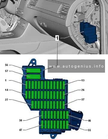
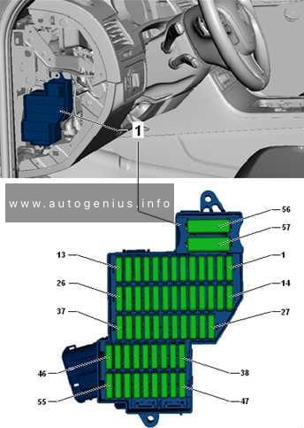
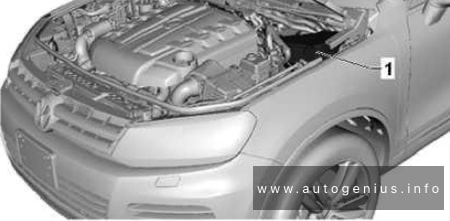
This article provides the second-generation Volkswagen Touareg (7P), manufactured between 2010 and 2018. It provides fuse box diagrams for the Volkswagen Touareg models from 2011 to 2018, along with details on the location of the fuse panels within the vehicle. Additionally, you’ll find information on the fuse layout and the functions of each fuse and relay.
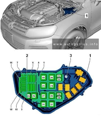
Fuse assignment in fuse box, right-side instrument panel
Assignment of the fuses in the right-side of the instrument panel
No.
А
Function/component
1
–
Not assigned
2
15
Adaptive suspension control unit -J197-
3
10
Axle differential lock control unit -J647-
4
30
Axle differential lock control unit -J647-
5
25
156
Trailer detector control unit -J345-
6
15
Trailer detector control unit -J345-
7
15
256
Trailer detector control unit -J345-
8
15
256
Trailer detector control unit -J345-
9
30
Rear right door control unit -J389-
10
–
Not assigned
11
30
Front passenger door control unit -J387-
12
–
Not assigned
13
15
Trailer detector control unit -J345-6
14
10
Airbag control unit -J234-
Front passenger airbag deactivated warning lamp -K145-
Seat occupied recognition control unit -J706-3
15
10
Transfer box control unit -J646-
16
5
Control unit for electromechanical parking brake -J540-
Operating unit to regulate suspension height -E281-
Left washer jet heater element -Z20-
Right washer jet heater element -Z21-
Button for TCS and electronic stabilisation program -E256-
ABS control unit -J104-
Hill descent control button -E618-
Electromechanical parking brake button -E538-
Auto-hold button -E540-6
Voltage stabiliser -J532-2
17
15
Front right headlight -MX2-
18
30
Igniter for front passenger side seat belt tensioner 2 -N298-
19
5
Tiptronic switch -F189-
Multifunction switch -F125-
Automatic gearbox control unit -J217-
20
25
Front passenger seat position control unit -J720-1
Valve block 1 in front passenger seat -N477-1
Control unit for front passenger multicontour seat -J872-1
Control unit for front right seat ventilation -J799-1
Front passenger seat rake adjustment button -E334-1
Front passenger seat longitudinal adjustment switch -E64-1
Front passenger side height adjustment switch -E290-1
Front passenger seat backrest adjustment switch -E98-1
Front passenger seat lumbar support adjustment switch -E177-1
21
25
Heated rear seats control unit -J786-1
Operating and display unit for rear air conditioning system -E265-1
22
–
Not assigned
23
25
Rear lid control unit -J605-
24
10
Climatronic control unit -J255-
Operating and display unit for rear air conditioning system -E265-1
25
5
Control unit for overhead view camera -J928-
Reversing camera system control unit -J772-
26
30
Heated rear window relay -J9-
27
5
Remote control receiver for auxiliary coolant heater -R149-
28
20
Gearbox hydraulic pump relay -J510-
Transfer box control unit -J646-
Automatic gearbox control unit -J217-
28
55
206
Transfer box control unit -J646-
29
30
ABS control unit -J104-
30
5
Tiptronic switch -F189-5
31
306,7
205
Convenience system central control unit -J393-
32
30
Rear fresh air blower -V80-4
33
30
Convenience system central control unit -J393-
34
–
Not assigned
35
5
Control unit for vehicle location system -J895-4
36
30
Convenience system central control unit -J393-
37
20
Automatic gearbox control unit -J217-5
Gearbox hydraulic pump relay -J510-5
38
15
Cigarette lighter -U1-
12 V socket 2 -U18-
Heated rear seats control unit -J786-
39
15
12 V socket 3 -U19-
12 V socket 4 -U20-
40
20
304
DC/AC converter with socket, 12 V – 230 V -U13-
41
10
Connection 2 for external audio sources -R231-5 Not assigned6
42
5
Trailer detector control unit -J345-
43
10
Axle differential lock control unit -J647-
44
5
Air quality sensor -G238-
45
30
Voltage stabiliser -J532-2
46
30
Voltage stabiliser -J532-2
47
10
Control unit 1 for information electronics -J794-
Display unit for front information display and operating unit control unit -J685-
48
30
Digital sound package control unit -J525-1
49
–
Not assigned
50
5
TV tuner -R78-1
Mobile telephone operating electronics control unit -J412-1
51
20
Radio -R-
52
5
Control unit in dash panel insert -J285-
53
5
DVD changer -R161-
54
5
Interface for external multimedia unit -R215-4
55
–
Not assigned
56
40
ABS control unit -J104-
57
40
Control unit for electromechanical parking brake -J540-
Transfer box control unit -J646-
1) According to equipment
2) Only models with start/stop system
3) Only for American markets
4) From November 2010
5) From November 2012
6) From August 2014
7) Up to November 2012
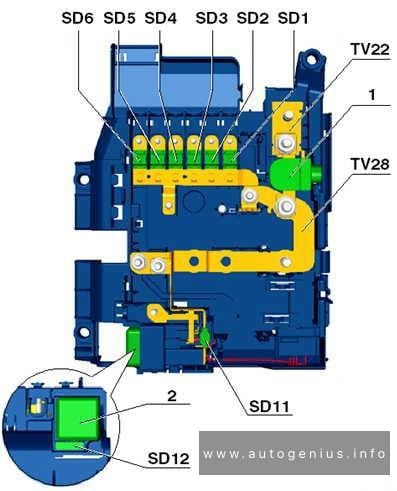
Fuse assignment in fuse box, left-side instrument panel
Radiator fan control unit -J293-
Automatic glow period control unit -J179-
Additional coolant pump relay -J496-
Brake light switch -F-
Exhaust gas recirculation cooler changeover valve -N345-
Exhaust gas recirculation cooling bypass valve -N386-
Valve for oil pressure control -N428-
Throttle valve module -J338-
Radiator fan control unit -J293-
Automatic glow period control unit -J179-
Additional coolant pump relay -J496-
Brake light switch -F-
Exhaust gas recirculation cooler changeover valve -N345-
Coolant valve for cylinder head -N489-
Valve for oil pressure control -N428-
Map-controlled engine cooling system thermostat -F265-
Right electrohydraulic engine mounting solenoid valve -N145-1
Radiator fan control unit -J293-
Automatic glow period control unit -J179-
Glow period control unit 2 -J703-
Additional coolant pump relay -J496-
Brake light switch -F-
Exhaust gas recirculation cooler changeover valve -N345-
Coolant valve for cylinder head -N489-
Valve for oil pressure control -N428-
Throttle valve module -J338-
11
15
Oil level and oil temperature sender -G266-
Heater element for crankcase breather -N79-
Heater element 2 for crankcase breather -N483-
The Ram 5500 Chassis Cab (2011) is the most heavy-duty truck in the Ram Chassis Cab lineup for that year, offering exceptional towing and payload capacities for demanding commercial applications. It is designed to be upfitted for various roles, including tow trucks, dump trucks, flatbeds, and other specialized commercial uses. The 2011 Ram 5500 is ideal for businesses that require a reliable, durable, and powerful vehicle capable of handling extreme loads and rough work environments.
Totally Integrated Power Module (TIPM)
Fuse box location
The totally integrated power module (TIPM) is located in the engine compartment near the battery
The Ram 4500 (2011) is a part of the Ram Chassis Cab lineup, designed for heavy-duty commercial applications. It was developed to handle demanding tasks like towing, hauling, and construction work. The Ram 4500 is positioned between the Ram 3500 and 5500 models, offering more capability than a standard pickup but less than the heaviest-duty versions.
Totally Integrated Power Module
Fuse Box Location
The totally integrated power module (TIPM) is located in the engine compartment near the battery.
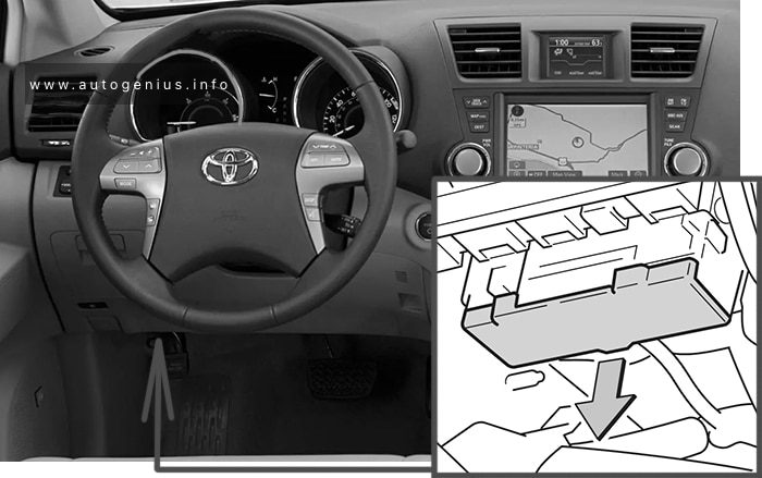
Toyota Highlander (XU40; 2011 – 2013) – fuse box diagram
Year of production: 2011, 2012, 2013
The Toyota Highlander XU40 crossover represents the 2nd generation of the Toyota Highlander model range. Years of production: 2007, 2008, 2009, 2010, 2011, 2012, 2013, 2014. During this time, the model has been restyled. In our material you can find a description of fuses and relays Toyota Highlander 2 with box diagrams and their locations.
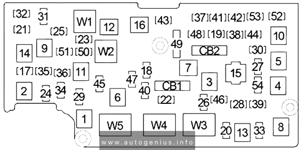
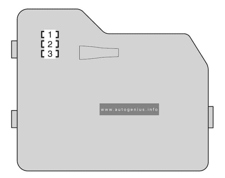
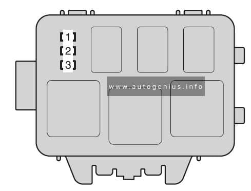
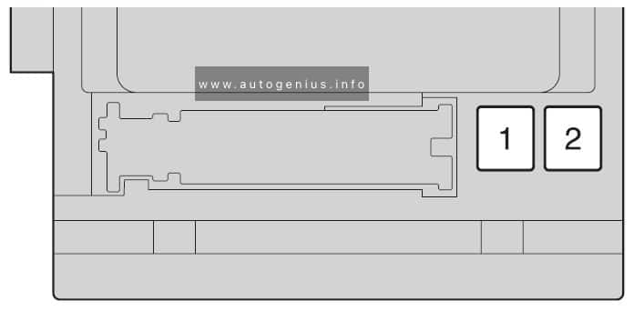
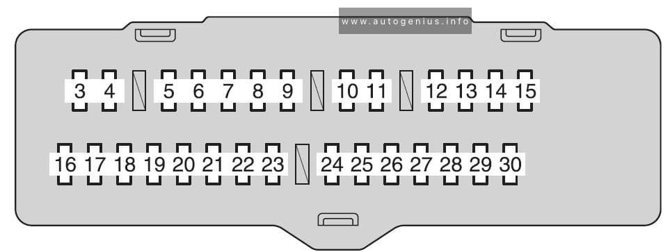
Engine compartment
Fuse box location
There are 2 fuse and relay boxes under the hood.
It is located in the engine compartment (left-side)
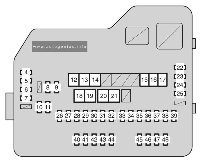
Multiport fuel injection system/sequential multiport fuel injection system
12
HTR
50
Air conditioning system
13
VSC NO.1
50
Enhanced vehicle stability control system
14
FAN MAIN
50
Electric cooling fan
15
VSC NO.2
30
Enhanced vehicle stability control system
16
PTC NO.1
50
Air conditioning system
17
PTC NO.2
30
Air conditioning system
18
PTC NO.3
30
Air conditioning system
19
RR CLR
40
Air conditioning system
20
RR DEF
30
Rear window defogger
21
PBD
30
Power back door
22
ALT
140
MIR HTR, PWR OUTLET, DOOR NO.1, HTR, RR DEF, FAN MAIN, VSC NO.1, PTC NO.1, RR CLR, PTC NO.2, PTC NO.3, VSC NO.2, PBD
23
EPS
80
Electric power steering
24
ST
30
Starting system
25
CRT
10
Rear seat entertainment system
26
RADIO NO.1
158
Audio system
27
ECU-B NO.1
10
Steering sensor, gauges and meters, clock, main body ECU,
wireless remote control, smart key system, power back door, multiinformation display, front passenger occupant classification system
28
DOME
10
Vanity lights, personal lights, interior light, gauges and meters, engine switch light, door courtesy lights
Year of production: 2005, 2006, 2007, 2008, 2009, 2010, 2011
Alfa Romeo 159 (939 series) is a mid-size car, produced by the company since 2005 with sedan and station wagon bodies (SPORTWAGON). This material will be useful for the owner of cars produced in 2006, 2007, 2008, 2009, 2010, 2011 to find and replace fuses and relays on the Alfa Romeo 159 car. We will also show box diagrams with a description of the elements and their location.
Locations
Vehicle fuses are grouped into four blocks:
in the passenger compartment
on the positive terminal of the storage battery
in the engine compartment
in the trunk (usually on the left side).
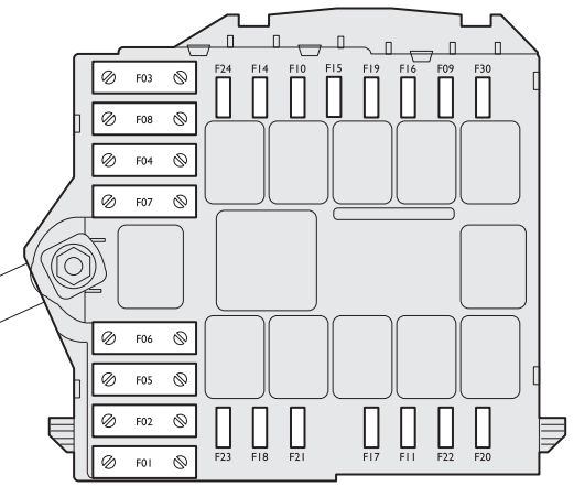
Fuse box on the dashboard
Located behind a plastic cover on the front panel. To access, unscrew the required 2 screws and remove the protective cover.
Alfa Romeo 159 – fuse box – dashboard
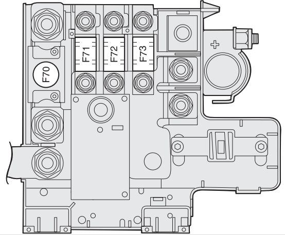
Fuse box on the battery positive pole
To access the fuse box on the battery terminal, press in on the latches and remove the protective cover.
Alfa Romeo 159 – fuse box – battery positive pole
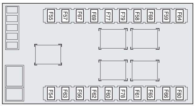
Fuse box near the battery
To access the fuse box next to the battery, you need to unscrew the screws.