RAM Cargo Van (2012 – 2015) – fuse and relay box diagram
Year of production: 2012, 2013, 2014, 2015
The Ram Cargo Van (2012–2015), also known as the Ram C/V Tradesman, was a commercial cargo vehicle based on the Dodge Grand Caravan platform. It was designed to serve businesses and tradespeople who needed a versatile, cost-effective solution for carrying equipment, goods, and materials. Chrysler introduced the Ram Cargo Van as part of the Ram commercial vehicle lineup after it split off Ram Trucks from the Dodge brand. The Ram C/V Tradesman was essentially a converted minivan with its interior reconfigured for commercial use, combining the utility of a cargo van with the drivability of a minivan.
This article covers the Ram Cargo Van (C/V Tradesman), produced between 2012 and 2015. It includes fuse box diagrams for the 2012, 2013, 2014, and 2015 models, along with information on the location of the fuse panels within the vehicle and details on the function of each fuse (fuse layout).
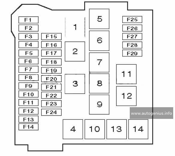
Totally Integrated Power Module
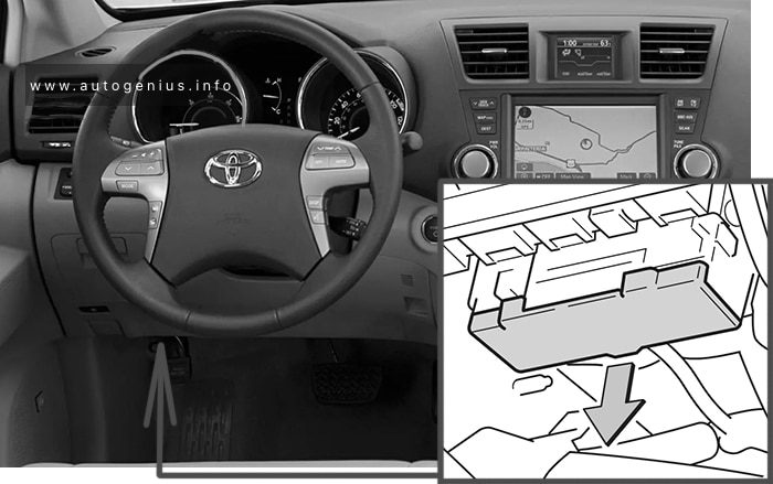
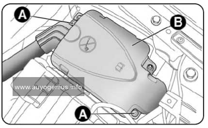
Fuse Box Location
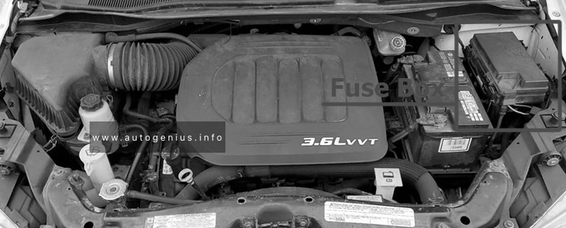
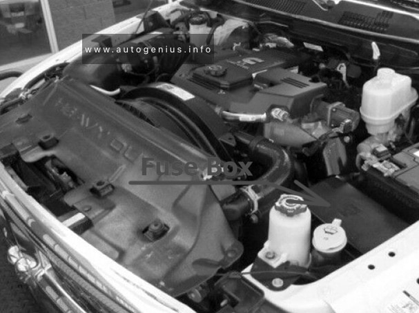
The Totally Integrated Power Module is located in the engine compartment near the battery.
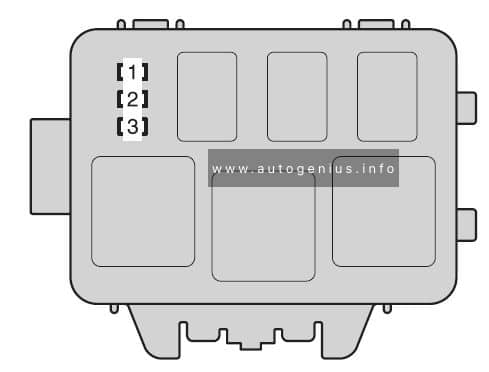
RAM Cargo Van – fuse and relay box location – engine compartment
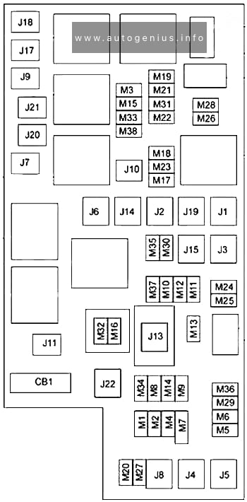
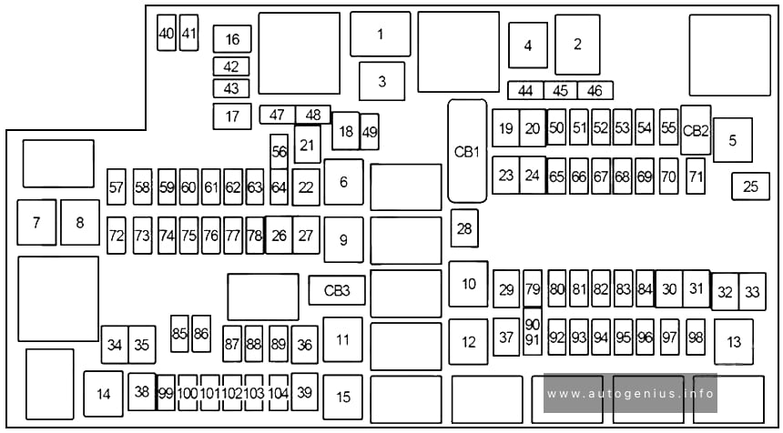
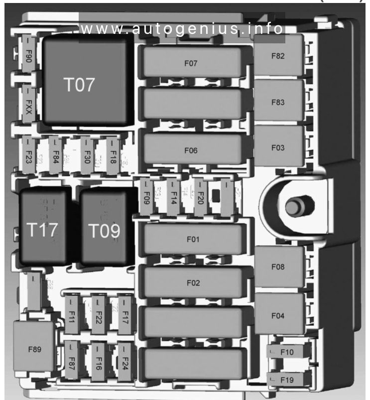
Fuse Box Diagram
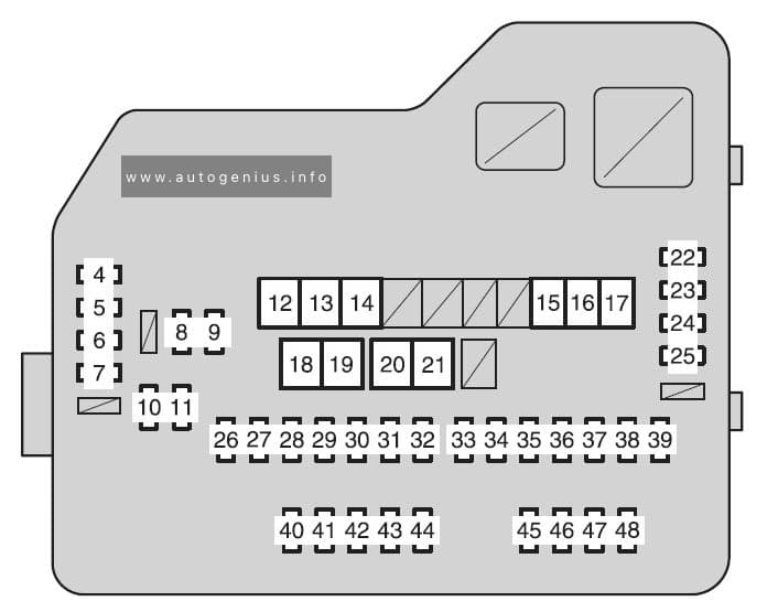
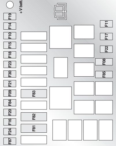
RAM Cargo Van – fuse and relay box diagram – engine compartment
Power windows:
2012: The power windows are fused by a 25 Amp circuit breaker located under the instrument panel near the steering column.
2013-2015: The power windows are fused by a 25 Amp circuit breaker located in the Totally Integrated Power Module.
Assignment of the fuses in the engine compartment
Cavity
Cartridge fuse
Micro Fuse
Description
J1
40
—
Power Folding Seat
J2
30
—
Power Liftgate Module
J3
30
—
Rear Door Module
J4
25
—
Driver Door Node
J5
25
—
Passenger Door Node
J6
40
—
Antilock Brakes Pump/Stability Control System
J7
30
—
Antilock Brakes Valve/Stability Control System
J8
40
—
Power Memory Seat – If Equipped
J9
40
Partial Zero Emissions Vehicle Motor/Flex Fuel – If Equipped
J10
30
—
Headlamp Wash/Manifold Tuning Valve – If Equipped
J11
30
—
Power Sliding Door Module/Anti–Theft Module – If Equipped
J12
30
—
HVAC Rear Blower, Radiator Fan Motor
J13
60
—
Ignition Off Draw (IOD) – Main
J14
40
—
Rear Window Defogger
J15
40
—
Front Blower
J17
40
—
Starter Solenoid
J18
20
—
Powertrain Control Module Trans Range
J19
60
—
Radiator Fan
J20
30
—
Front Wiper LO/HI
J21
20
—
Front/Rear Washer
J22
25
—
Sunroof Module
M1
—
15
Rear Center Brake Lamp/Brake Switch
M2
—
20
Front Fog Lamps
M3
—
20
Front/Rear Axle Locker, Vacuum Pump Motor
M4
—
10
Trailer Tow
M5
—
25
Inverter
M6
—
20
Power Outlet #1 (ACC), Rain Sensor, Cigar Lighter (Instrument Panel or with Console Rear)
M7
—
20
Power Outlet #2 (BATT/ACC SELECT) – Center Seat or with Console Rear
M8
—
20
Front Heated Seat – If Equipped
M9
—
20
Rear Heated Seat – If Equipped
M10
—
15
Ignition Off Draw — Video System, Satellite Radio, DVD, Hands-Free Module, Universal Garage Door Opener, Vanity Lamp, Streaming Video Module – If Equipped
M11
—
10
Climate Control System
M12
—
30
Amplifier/Radio
M13
—
20
Instrument Cluster, SIREN, Clock Module, Multi-Function Control Switch – If Equipped
M14
—
20
Trailer Tow – If Equipped
M15
—
20
Rear View Mirror, Instrument Cluster, Multi-Function Control Switch, Tire Pressure Monitor, Glow Plug Module – If Equipped
Park Assist, Heater Climate Control Module, Headlamp Wash, Compass, Rear Camera, Door Lamps, Flashlight, Relay Diesel Cabin Heater, Rad Fan Diesel – If Equipped
M35
—
10
Heated Mirrors
M36
—
20
Power Outlet #3 (Instrument Panel or with Console Center)
The Ram 5500 Chassis Cab (2013-2015) is a top-tier heavy-duty commercial truck designed for demanding tasks that require maximum power, towing, and payload capabilities. As the largest model in the Ram Chassis Cab lineup, it offers exceptional strength and versatility, making it ideal for various industries such as construction, towing, and custom upfit needs. Built for reliability and durability, the Ram 5500 is well-suited for heavy-duty applications.
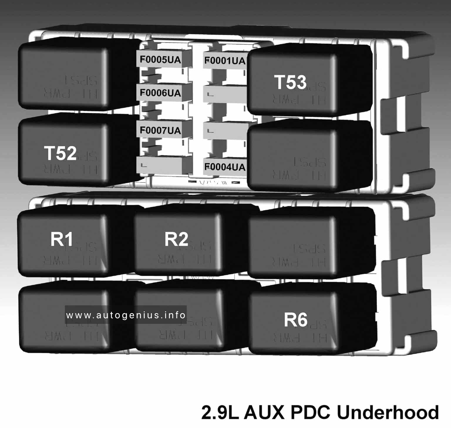
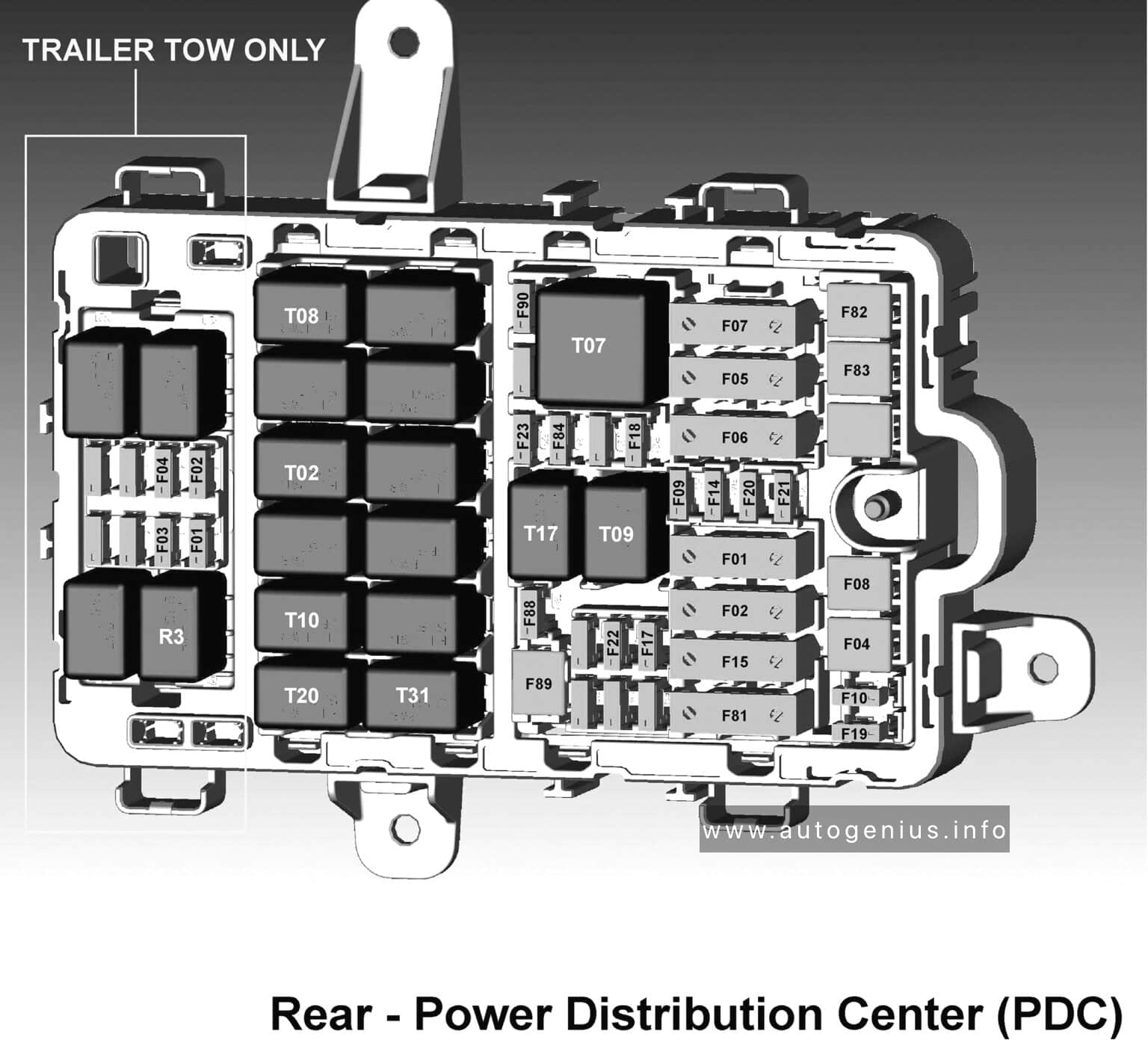
Power Distribution Center
Fuse box location
The Power Distribution Center is located in the engine compartment near the battery.
The Ram 4500 Chassis Cab (2013 – 2015) is a heavy-duty commercial vehicle designed to handle demanding jobs requiring high towing and payload capacities. It sits between the Ram 3500 and 5500 in the Ram Chassis Cab lineup, offering excellent versatility and customization options for industries such as construction, towing, and utility services.
Power Distribution Center
Fuse box location
The Power Distribution Center is located in the engine compartment near the battery.
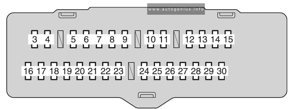
Toyota Highlander (XU40; 2011 – 2013) – fuse box diagram
Year of production: 2011, 2012, 2013
The Toyota Highlander XU40 crossover represents the 2nd generation of the Toyota Highlander model range. Years of production: 2007, 2008, 2009, 2010, 2011, 2012, 2013, 2014. During this time, the model has been restyled. In our material you can find a description of fuses and relays Toyota Highlander 2 with box diagrams and their locations.
Engine compartment
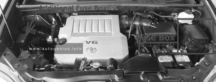
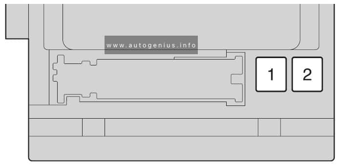
Fuse box location
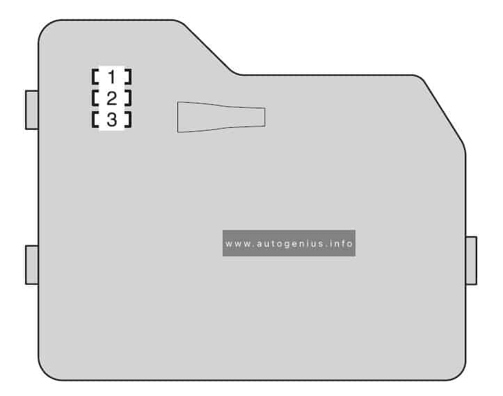
There are 2 fuse and relay boxes under the hood.
It is located in the engine compartment (left-side)
Multiport fuel injection system/sequential multiport fuel injection system
12
HTR
50
Air conditioning system
13
VSC NO.1
50
Enhanced vehicle stability control system
14
FAN MAIN
50
Electric cooling fan
15
VSC NO.2
30
Enhanced vehicle stability control system
16
PTC NO.1
50
Air conditioning system
17
PTC NO.2
30
Air conditioning system
18
PTC NO.3
30
Air conditioning system
19
RR CLR
40
Air conditioning system
20
RR DEF
30
Rear window defogger
21
PBD
30
Power back door
22
ALT
140
MIR HTR, PWR OUTLET, DOOR NO.1, HTR, RR DEF, FAN MAIN, VSC NO.1, PTC NO.1, RR CLR, PTC NO.2, PTC NO.3, VSC NO.2, PBD
23
EPS
80
Electric power steering
24
ST
30
Starting system
25
CRT
10
Rear seat entertainment system
26
RADIO NO.1
158
Audio system
27
ECU-B NO.1
10
Steering sensor, gauges and meters, clock, main body ECU,
wireless remote control, smart key system, power back door, multiinformation display, front passenger occupant classification system
28
DOME
10
Vanity lights, personal lights, interior light, gauges and meters, engine switch light, door courtesy lights
Year of production: 2013, 2014, 2015, 2016, 2017, 2018
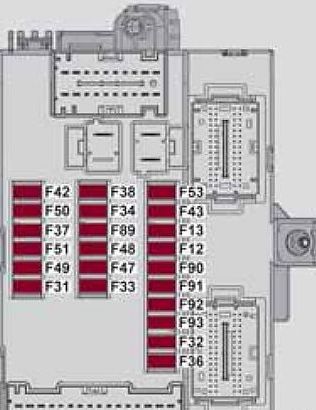
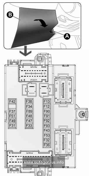
The Alfa Romeo MiTo (Series 955) was first introduced in 2008 and underwent a restyling in 2014. Although there were no significant external changes, a new trim for the headlight surround and a chrome grille were added. Internal changes varied depending on the configuration and year of manufacture. This article focuses on the fuse and relay boxes of the Alfa Romeo MiTo from 2009 to 2018, providing diagrams and locations.
Front roof light, Luggage compartment roof light, Sun visor courtesy light, Door puddle lights, Glove compartment light
F32
5
Radio, sound system setup system (for versions/markets, where provided), Uconnect ™ 5″ radio (for versions/markets, where provided), climate control system control unit, alarm system control unit, volumetric system control unit, EOBD external diagnosis socket, tyre pressure monitoring control unit
F36
10
Instrument panel, brake light on switch
F37
5
Door lock motor on doors, Safe Lock motor on doors, Tailgate unlocking motor
F38
15
Windscreen/rear window washer pump
F43
20
Electric window motor complete with control unit (driver side door)
F47
20
Electric window motor complete with control unit (passenger side door)
F48
20
Parking sensor control unit, Tire pressure control unit, Rain sensor, automatic headlight switch on the interior rearview mirrors, electrochromic (convex) interior rearview mirror, radio navigation (backlight), LED on the display indicating that the seat belts are fastened on the interior rearview mirror, illumination of controls (center dashboard, driver side dashboard, steering wheel controls, Blue & Me controls), front seat heating switches, volumetric alarm control unit, electric sunroof control, PND connector on the dashboard
F49
5
Clutch activation switch, brake light switch, relay switch coils on engine fuse box control unit, control system on internal climate control/heater unit, flow meter, water presence in diesel sensor, radio, radio setup system (for versions/markets, where provided)
F51
5
nstrument pane
F51
5
* – For versions/markets, where provided
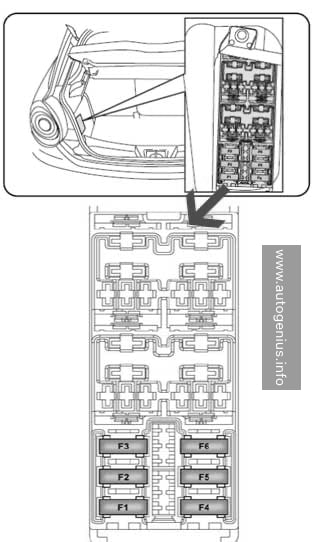
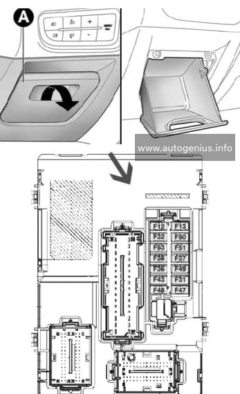
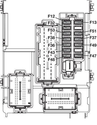
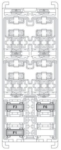
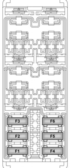
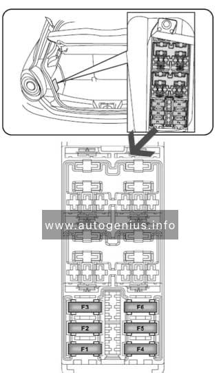
Luggage compartment fuse box
Located on the left under the casing.
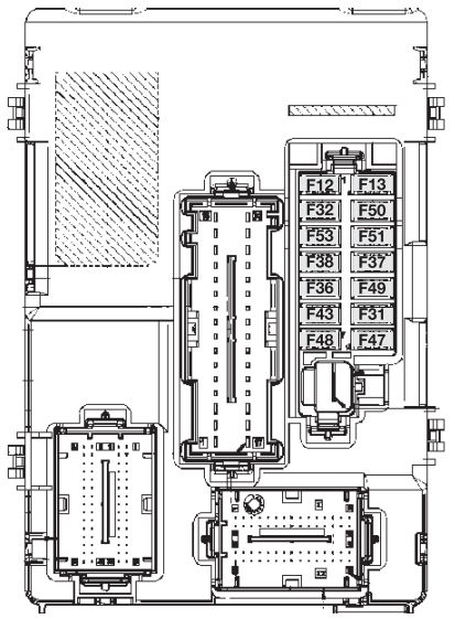
Alfa Romeo MiTo FL – fuse box – luggage
Device protected
Fuse
Ampere rating [A]
Bose HI-FI amplifier control unit
F4
15A
Bassbox subwoofer in the spare wheel compartment
F5
10A
Heated front left and right seats
F6
15A
Electric hatch opening system
F1
20A
Wiring fuses
F2
–
Trunk power socket
F3
15A
WARNING: Terminal and harness assignments for individual connectors will vary depending on vehicle equipment level, model, and market.
Year of production: 2008, 2009, 2010, 2011, 2012, 2013
The Alfa Romeo MiTo (Series 955) was first introduced in 2008 and underwent a restyling in 2014. Although there were no significant external changes, a new trim for the headlight surround and a chrome grille were added. Internal changes varied depending on the configuration and year of manufacture. This article focuses on the fuse and relay boxes of the Alfa Romeo MiTo from 2009 to 2018, providing diagrams and locations.
Front courtesy light, luggage compartment light, Sun visor courtesy light, Door lights, Glove compartment light
F32
5
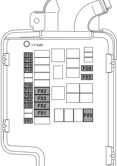
Dashboard
Consumers
Fuse
Ampere rating [A]
Location
Passenger compartment fan
F08
30
Engine compartment
Headlight washer pump
F09
20
Engine compartment
Two-tone horn
F10
15
Engine compartment
Waste gate solenoid, Shut off solenoid, Canister solenoid, Lambda Sensor Heater, VGT solenoid, EGR cooling bypass solenoid, Swirl solenoid, Throttle solenoid, Glow plug preheating control unit
F11
10
Engine compartment
Headlight alignment adjustment system
f13
7,5
Dashboard
Additional heater (PTC 1)
F15
30
Engine compartment
Engine management control unit
F16
5
Engine compartment
Engine management control unit (power supply)
F17
10
Engine compartment
Control system relay coil, Engine management control unit (1.4 versions), Engine cooling system remote control switch coil (300W+300W)
F18
5
Engine compartment
Air conditioning compressor
F19
7,5
Engine compartment
Heated rear windscreen, demisting system
F20
30
Engine compartment
Fuel pump on tank
F21
15
Engine compartment
Engine management system main loads (1.4 versions)
F22
10
Engine compartment
Engine management system main loads (1.6 JTDM versions)
F22
20
Engine compartment
Braking system control unit (control unit and solenoid unit)
F23
20
Engine compartment
Electric steering control unit (power supply + Key), Brake system control unit (power supply + Key), Yaw sensor on tunnel
F24
5
Engine compartment
INT/A key exhaust relay coils on engine fuse box
F31
5
Dashboard
Radio, Blue&MeTM control unit, Climate control unit, Alarm control unit, Volume sensing system control unit, EOBD external diagnostic socket, Tyre pressure detection control unit
F36
10
Dashboard
Instrument panel, Brake light switch, Gas discharge headlights management system
F37
5
Dashboard
Door lock motor on door, Safe Lock motor on doors, Tailgate unlocking motor
F38
15
Dashboard
Windscreen / rearscreen washer pump
F43
20
Dashboard
Electric window motor complete with control unit (driver-side door)
F47
20
Dashboard
Electric window motor complete with control unit (passenger-side door)
F48
20
Dashboard
Parking sensors control unit, Tyre pressure detection control unit, Rain/dusk sensor on rear-view mirror, Electro-chrome sensor on rear-view mirror, Seat belts fastened warning light display on rear-view mirror, Control panel illumination (Central control panel, Driver-side control panel, Steering wheel control panel, Blue&MeTM control panel), Front seat heating pad activation switch, Alarm system volume-sensing sensors control unit, Electric sunroof control unit, PND socket on dashboard
F49
5
Dashboard
Air Bag system control unit
F50
7,5
Dashboard
Clutch switch, Brake light switch, relay coils on engine fuse box, Control system on internal heater/air conditioning unit, Blue&MeTM control unit, Radio wiring, Air flow meter, Water in diesel fuel sensor
F51
5
Dashboard
Instrument panel
F53
5
Dashboard
Bose HI-FI system amplifier control unit
F4
15
Luggage
Bassbox subwoofer in spare wheel compartment
F5
10
Luggage
Left and right front seat heater
F6
15
Luggage
Electric sunroof opening system
F1
20
Luggage
Fuse wiring
F2
—
Luggage
Luggage compartment power socket
F3
15
Luggage
Passenger compartment fan
F83
40
Engine compartment
Power socket on tunnel
F85
15
Engine compartment
Passenger/driver-side door mirror demister, Demister on front jets, Heated windscreen relay coil
F87
7,5
Engine compartment
WARNING: Terminal and harness assignments for individual connectors will vary depending on vehicle equipment level, model, and market.
Year of production: 2013, 2014, 2015, 2016, 2017, 2018, 2019, 2020
Alfa Romeo Giulietta is a compact hatchback produced since 2010. It was created as the older model of the Alfa Romeo MiTo. Our material will help owners of Alfa Romeo Giulietta 2011, 2012, 2013, 2014, 2015, 2016, 2017, 2018, 2019, 2020 (During this time, the model underwent a facelift several times.) in finding and replacing fuses and relays. We will also show fuse box diagrams and locations. NOte the cigarette lighter fuse.
There are 3 main fuse boxes in this model. One is in the engine compartment, the second is in the passenger compartment under the dashboard, and the third is in the luggage compartment.