Volkswagen Transporter (T5.1; 2010 – 2015) – fuse box diagram
Year of production: 2010, 2011, 2012, 2013, 2014, 2015
This article covers the post-facelift fifth-generation Volkswagen Transporter (T5.1), manufactured from 2009 to 2015. It provides fuse box diagrams for Volkswagen Transporter T5.1 models from 2010 to 2015, along with details on the location of the fuse panels within the vehicle and the specific functions of each fuse (fuse layout).
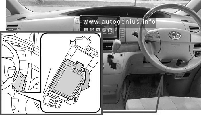
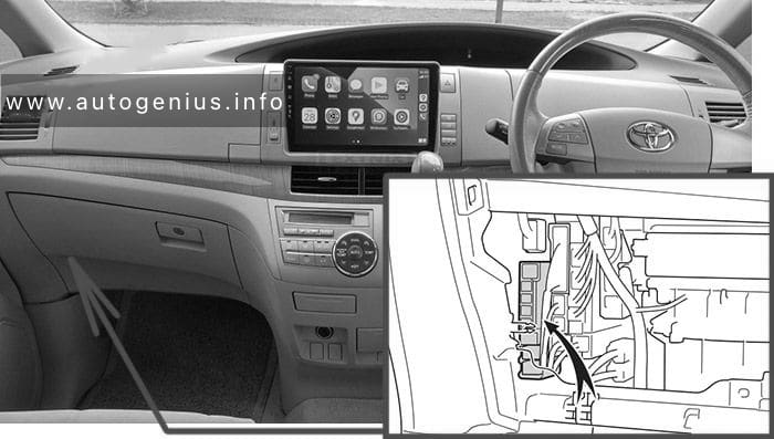
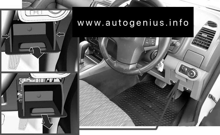
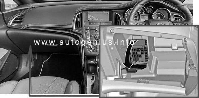
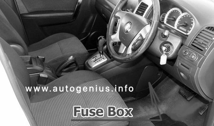
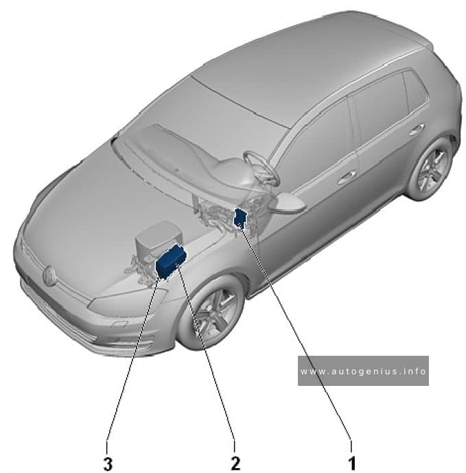
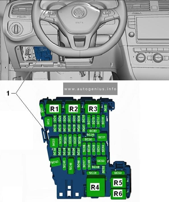
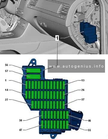
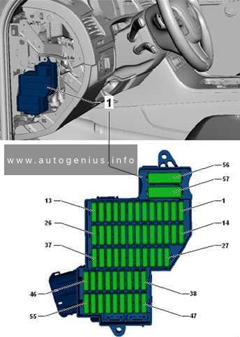
Passenger Compartment Fuse Boxes
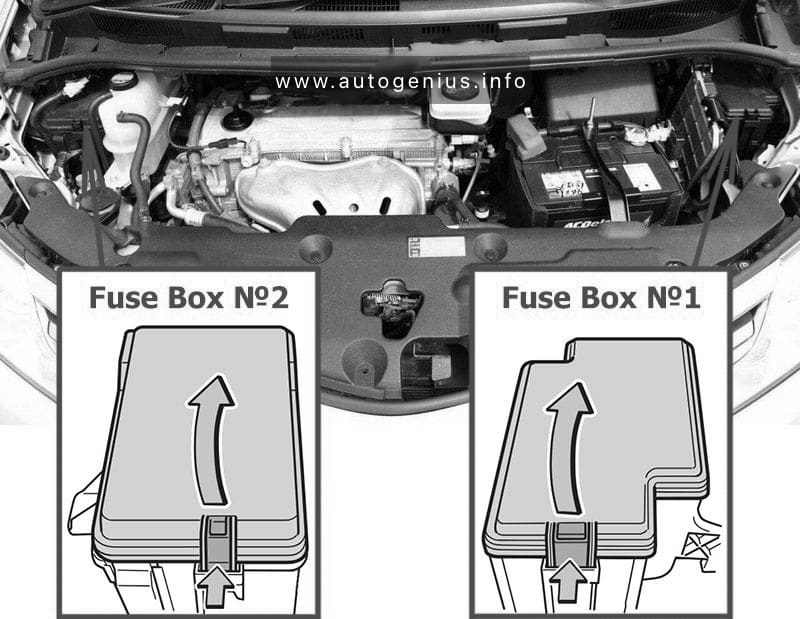
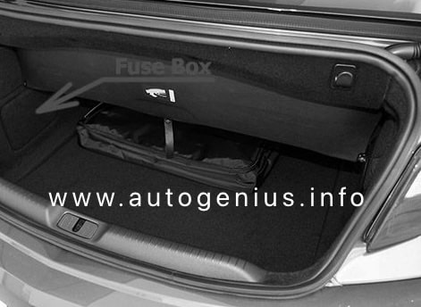
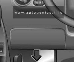
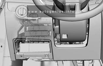
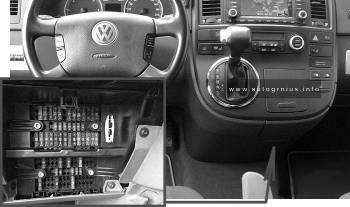
Fuse Box Location
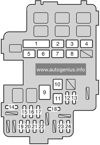
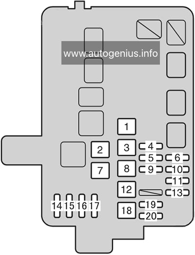
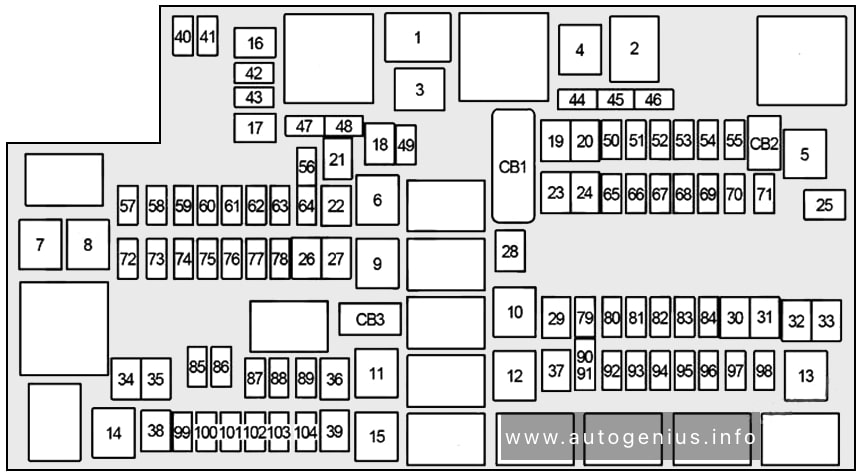
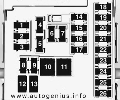
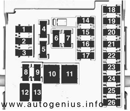
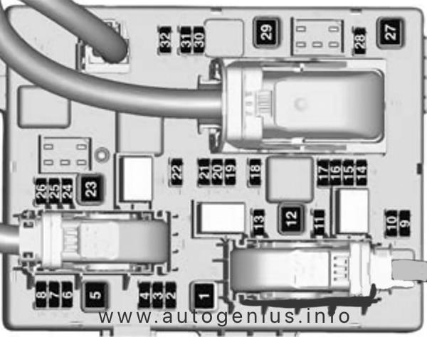
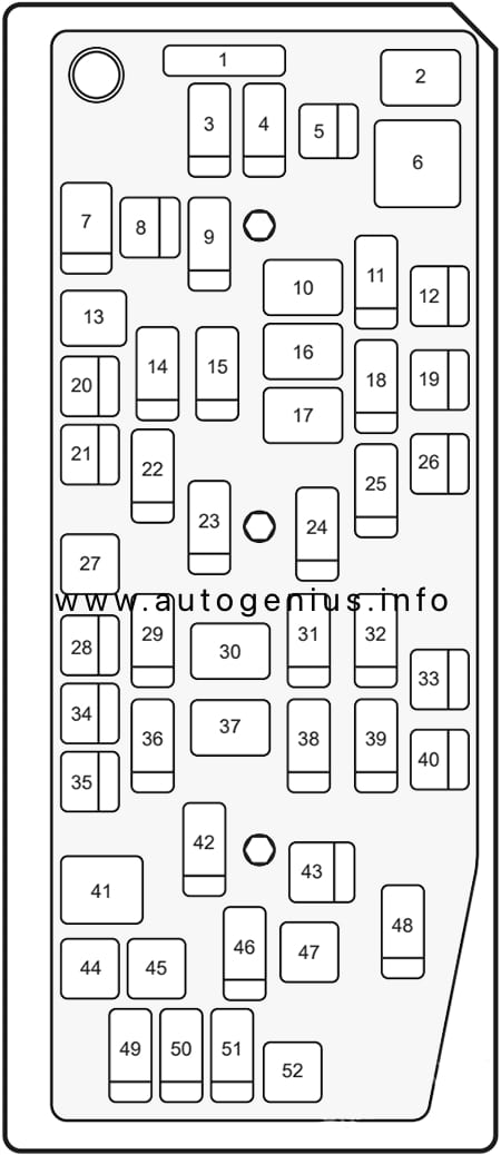
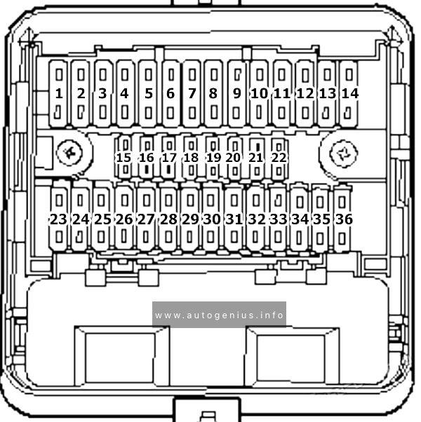
Fuse Box Diagram (-SB-, -SC-)
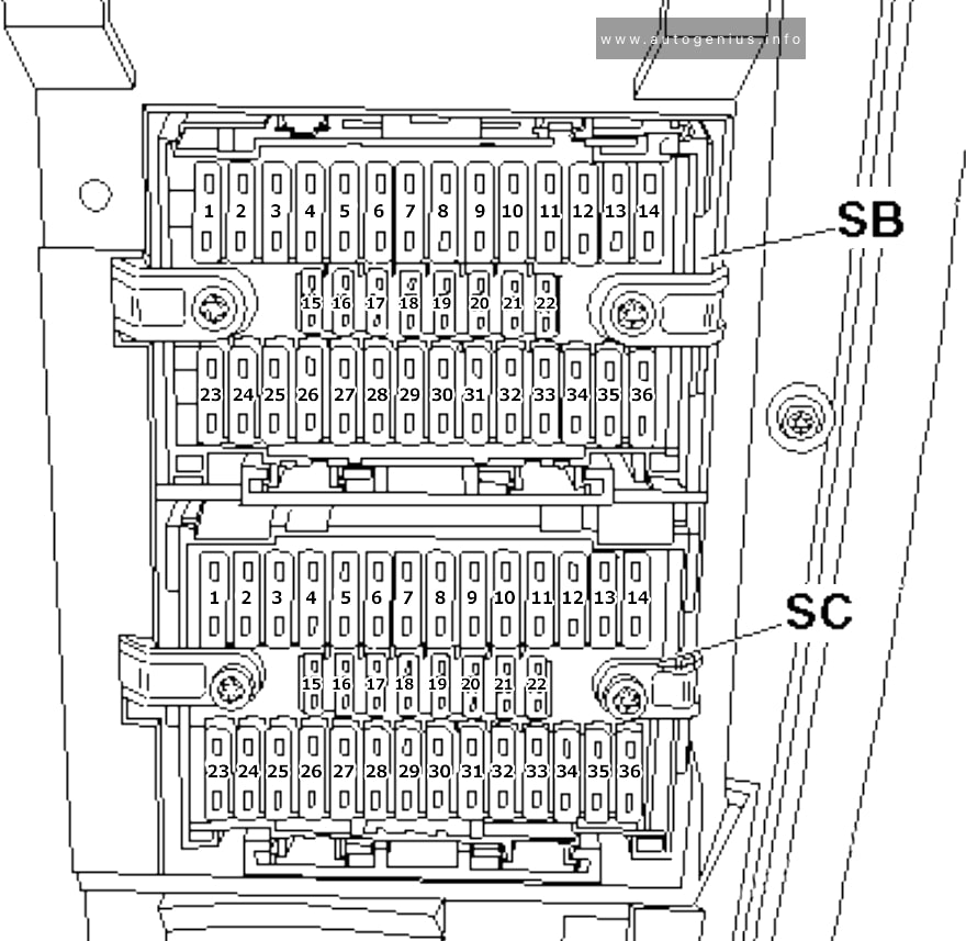
Assignment of the fuses in the instrument panel (fuse holders C and B)
| № | Amps | Function/component |
|---|---|---|
| Fuse holder B | ||
| SB1 | 30A | Terminal 15 voltage supply relay |
| SB2 | 5A | Steering angle sender |
| SB3 | 10A | Onboard supply control unit |
| SB4 | 5A | Lane change assist control unit Lane change assist control unit 2 |
| SB5 | 15A | Front left headlight |
| SB6 | 15A | Front left headlight |
| SB7 | 15A | Onboard supply control unit |
| SB8 | 15A | Rear lid control unit -J605- |
| SB8 | 20A | Alarm horn Onboard supply control unit Left sliding door control unit Rear lid control unit Right sliding door control unit |
| SB9 | 30A | Onboard supply control unit |
| SB10 | 10A | Intermittent wiper switch Rear wiper switch Intermittent wiper regulator Washer pump switch (automatic wash/wipe and headlight washer system) |
| SB11 | 5A | Number plate light |
| SB12 | 5A/30A | Light switch |
| SB13 | 10A | Airbag control unit Front passenger side airbag deactivated warning lamp |
| SB14 | 25A | Headlight dipper/flasher switch |
| SB15 | 7,5A | Fresh air blower switch Rear fresh air blower switch Fresh air blower isolation relay |
| SB16 | 5A | Onboard supply control unit |
| SB17 | 5A | Rear fog light cut-out contact switch Control unit in dash panel insert Rear left fog light bulb |
| SB18 | 5A | Control unit in dash panel insert |
| SB19 | 5A | Operating and display unit for camping equipment Onboard supply control unit 10-pin connector (only models with electric interface, for external use) |
| SB20 | 5A | Diagnostic connection Differential lock control unit (2011-2015) |
| SB21 | 5A | Starter motor relay Engine control unit 10-pin connector (only models with electric interface, for external use) |
| SB22 | 7,5A | Light switch Control unit in dash panel insert Trailer detector control unit Diagnostic connection |
| SB23 | 5A | only models with electric interface, for external use: Starter inhibitor relay Onboard supply control unit Engine control unit 10-pin connector |
| SB23 | 30A | Starter Starter inhibitor relay Engine control unit |
| SB23 | 30A | Starter inhibitor relay Starter inhibitor relay, clutch pedal switch |
| SB24 | 5A | Steering angle sender |
| SB25 | 7,5A | Fresh air blower switch Front blower Bitron regulation sender Climatronic control unit Air conditioning system control unit |
| SB26 | 30A | Light switch |
| SB27 | 15A | Front right headlight |
| SB28 | 15A | Front right headlight Control unit in dash panel insert |
| SB29 | – | – |
| SB30 | 10A | Left washer jet heater element Right washer jet heater element Rear window wiper motor Rear right wing door window wiper motor Rear left wing door window wiper motor |
| SB31 | 30A | Onboard supply control unit |
| SB32 | 30A | Onboard supply control unit |
| SB33 | 30A | Radio Control unit with display for radio and navigation system |
| SB34 | 25A | Fuse 14 on fuse holder D Fuse 17 on fuse holder D Fuse 20 on fuse holder D Fuse 24 on fuse holder D |
| SB35 | 5A | Connection (58s), in roof wiring harness Connection 1 (58d), in main wiring harness Connection 2 (58d), in main wiring harness Connection 3 (58d), in main wiring harness Connection (58b), in driver side door wiring harness |
| SB36 | 25A | Onboard supply control unit -J519- (T73a/13) |
| Fuse holder C | ||
| SC1 | 15A | 10-pin connector |
| SC2 | 5A | Interior monitor send and receive module 1 Interior monitor send and receive module 2 |
| SC3 | 10A | Red Cross light switch Red Cross light warning lamp |
| SC3 | 15A | Taxi meter Taxi alarm remote control, control unit |
| SC4 | 10A | Rear differential lock switch Rear differential lock vacuum switch Differential lock control unit Four-wheel drive control unit |
| SC5 | 10A | 6-pin connector |
| SC6 | 5A | Oil level and oil temperature sender |
| SC7 | 10A | Rotating light switch |
| SC7 | 30A | Alarm system control unit |
| SC8 | 5A | Parking aid control unit |
| SC9 | 5A | Cruise control system switch |
| SC10 | 10A | Switches and instruments illumination regulator Headlight range control, control unit Left headlight range control motor Right headlight range control motor |
| SC11 | 15A | Taxi meter Taxi alarm system 2 control unit Alarm system relay 1 Taxi alarm remote control, control unit Two-way radio |
| SC12 | 5A | Front left headlight |
| SC12 | 30A | Onboard supply control unit |
| SC13 | 5A | Drive train CAN bus isolation relay |
| SC14 | 5A | Front right headlight |
| SC14 | 30A | Onboard supply control unit |
| SC15 | 5A | Mobile telephone operating electronics control unit Voice amplification control unit |
| SC16 | 7,5A | Interface for external multimedia unit TV tuner |
| SC17 | 7,5A | Onboard supply control unit Interior light and luggage compartment light Interior monitor deactivation switch Automatic anti-dazzle interior mirror |
| SC18 | 5A | Rear fresh air blower switch |
| SC18 | 5A | Operating and display unit for rear Climatronic Rear blower regulation sender |
| SC19 | 5A | Automatic anti-dazzle interior mirror |
| SC20 | 10A | Onboard supply control unit |
| SC21 | 5A | Rain sensor |
| SC22 | 10A | High pressure sender Air quality sensor Air conditioning system relay Coolant shut-off valve relay |
| SC23 | 7,5A/10A | Operating and display unit for camping equipment Roof display unit Residual heat relay Remote control receiver for auxiliary heating Remote control receiver for auxiliary coolant heater |
| SC24 | 7,5A | Interior light and luggage compartment light |
| SC25 | 25A | Heated front seats control unit |
| SC26 | 10A | Tachograph |
| SC27 | 30A | Terminal 15 voltage supply relay 2 |
| SC28 | 5A | Mirror adjustment switch Mirror adjustment change-over switch |
| SC29 | 20A | Heater control unit |
| SC30 | 5A | Operating and display unit for camping equipment |
| SC30 | 5A | Auxiliary coolant heater relay |
| SC31 | 5A | Onboard supply charger unit |
| SC31 | 25A | Sliding sunroof adjustment control unit |
| SC32 | 20A | Headlight washer system relay |
| SC33 | 5A | Tachograph |
| SC34 | 5A | Airbag coil connector and return spring with slip ring Multifunction steering wheel control unit |
| SC35 | 20A | Onboard supply control unit |
| SC36 | 5A | Operating and display unit for camping equipment 10-pin connector (only models with electric interface, for external us) 10-pin connector (for optimal equipment police (UF4/UF5) only) |
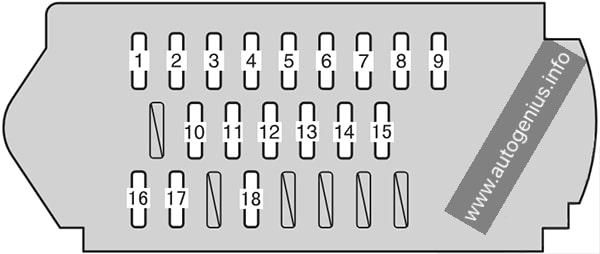
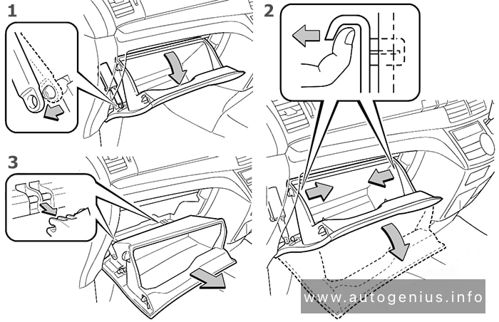
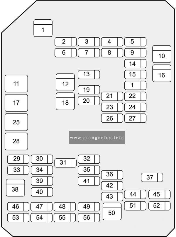
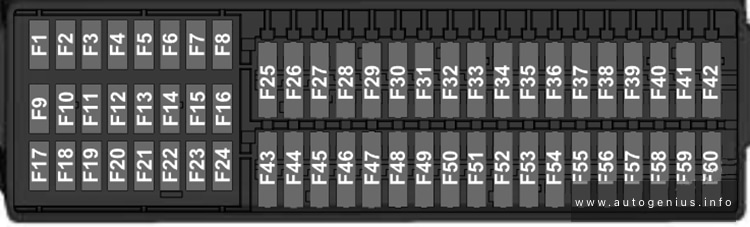
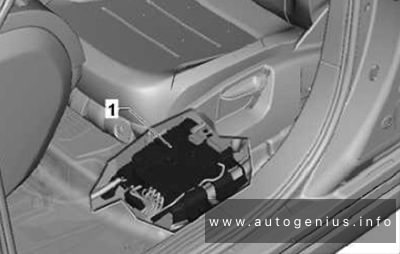
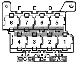
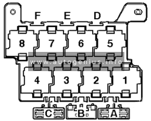
Fuse Holder F
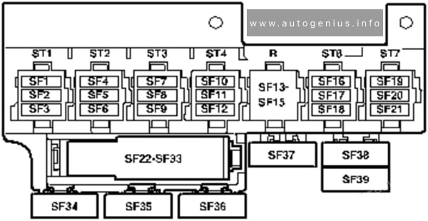
Assignment of the fuses in the instrument panel (fuse holders F)
| № | Amps | Function/component |
|---|---|---|
| 1 | 5A | 10-pin connector (models with electric interface, for external use) 6-pin connector |
| 2 | 3A | 10-pin connector (models with electric interface, for external use) |
| 3 | 15A | 10-pin connector (models with electric interface, for external use) Accident data memory |
| 3 | 5A | Accident data memory |
| 4 | 15A | 10-pin connector (models with electric interface, for external use) |
| 5 | 5A | 10-pin connector (models with electric interface, for external use) |
| 6 | 25A | 6-pin connector (models with electric interface, for external use) |
| 7 | 15A | 12V socket |
| 7 | 30A | Transformer with socket, 12V – 230V/115V (camper only, not for camper Beach) |
| 8 | 20A | Heater control unit |
| 8 | 25A | Auxiliary heater control unit |
| 9 | 25A | Rear fresh air blower switch Fresh air blower isolation relay |
| 9 | 30A | Rear fresh air blower switch Fresh air blower isolation relay Rear fresh air blower |
| 10 | 15A/30A | Fresh air blower switch Auxiliary heater relay Air conditioning system control unit Fresh air blower series resistor with overheating fuse |
| 11 | 15A | Cigarette lighter |
| 12 | 5A | 10-pin connector (models with electric interface, for external use) 6-pin connector Accident data memory |
| 13 | ||
| 14 | ||
| 15 | ||
| 16 | 30A | Onboard supply charger unit (camper only, not for camper Beach) |
| 17 | 30A | Roof hydraulics control unit (camper only, not for camper Beach) |
| 18 | 10A | Camper only, not for camper Beach: Map reading light bulb Rear right reading light Right interior light Luggage compartment light on left Kitchenette light 1 Kitchenette light 2 Kitchenette light 3 |
| 19 | 10A | Camper only, not for camper Beach: Refrigerator box |
| 20 | 5A | Camper only, not for camper Beach: Water pump switch Water pump |
| 21 | 5A | Camper only, not for camper Beach: Operating and display unit for camping equipment |
| 22 | 15A | 12V socket 2 |
| 23 | 15A | 12V socket 3 |
| 24 | 10A | Switch-over relay 1 for roof ventilator Switch-over relay 2 for roof ventilator Switch for roof ventilator to ventilate load area Switch for roof ventilator to extract air from load area |
| 24 | 15A | 12V socket 4 |
| 25 | 15A | Trailer detector control unit |
| 26 | 20A | Trailer detector control unit |
| 27 | 20A | Trailer detector control unit |
| 28 | 7,5A | Reversing camera system control unit |
| 29 | – | – |
| 30 | 5A | 2020: Voice amplification control unit |
| 31 | – | – |
| 32 | – | – |
| 33 | 15A | Driver seat lumbar support adjustment switch |
| 34 | 40A | Right sliding door control unit |
| 35 | 80A | Battery isolation relay Second battery charging circuit relay |
| 36 | 40A | Left sliding door control unit |
| 37 | 40A | Fresh air blower (models with second battery) |
| 38 | 40A | 6-pin connector (models with electric interface, for external use) |
| 39 | – | – |
| Equipment camper Beach only: | ||
| S131 | 10A | Right interior light Rear right interior light Kitchenette light 1 Kitchenette light 3 |
| S132 | 10A/15A | 12V socket |
| S133 | 15A | 12V socket 5 Rear left reading light Kitchenette light 2 |
Coupling station on left of seat box (10-pin)
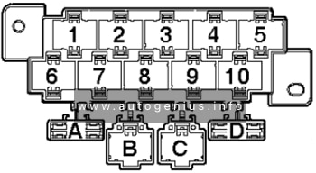
| № | Amps | Function/component |
|---|---|---|
| A | – | – |
| B | – | – |
| C | – | – |
| D | 30A | Amplifier |
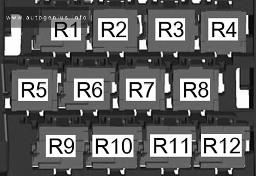
Fuses on relay carrier 1 (cockpit) 8-pin
Under dash panel (center, under the fuses).
| № | Amps | Function/component |
|---|---|---|
| 6 | 15A | Alarm system control unit (Taxi) |
| 6 | 10A | Taxi alarm system 2 control unit (Taxi) |
| A | – | – |
| B | 30A | Driver door control unit Front passenger door control unit |
| C | – | – |
Fuses on relay carrier 2 (cockpit) 8-pin
Under dash panel (center, under the fuses).
| № | Amps | Function/component |
|---|---|---|
| A | – | – |
| B | – | – |
| C | 40A | Fresh air blower switch Air conditioning system control unit |
| C | 40A | Fresh air blower switch Air conditioning system control unit Auxiliary coolant heater relay (models with auxiliary heating) Fresh air blower |
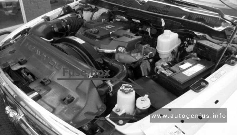
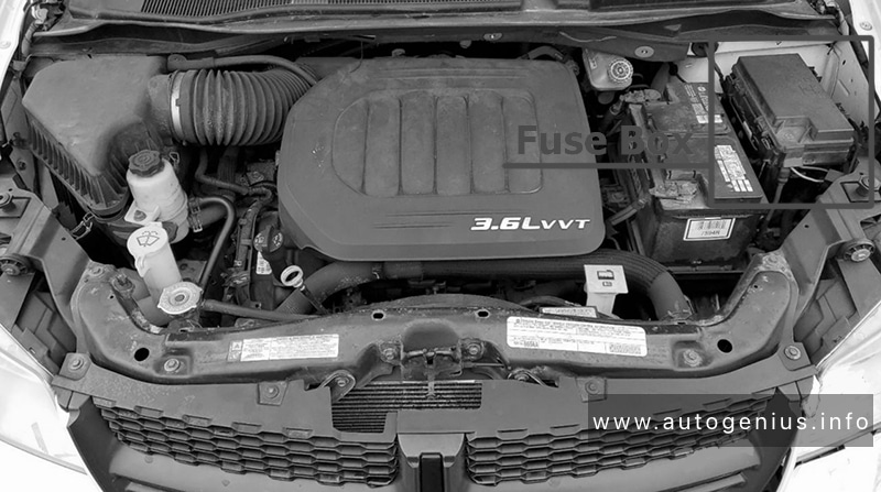
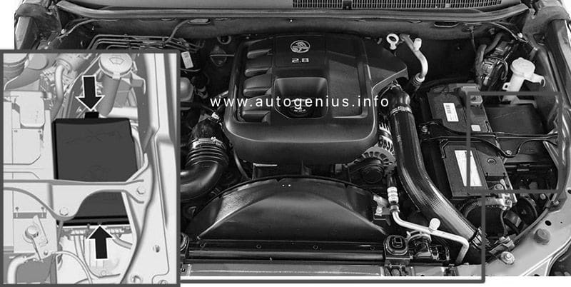
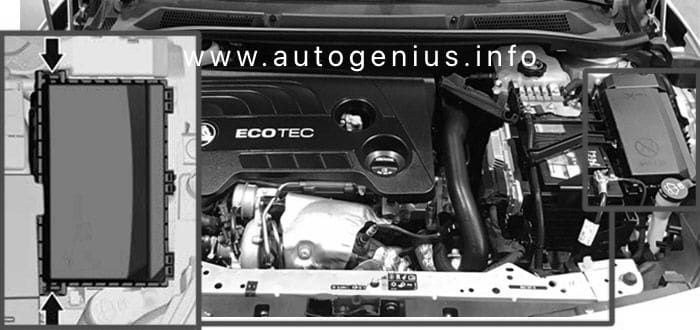
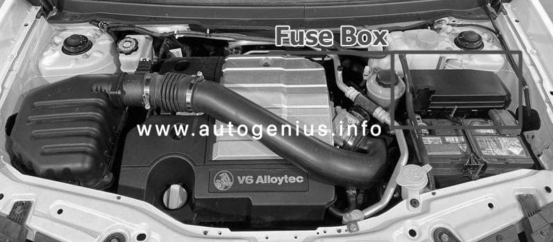
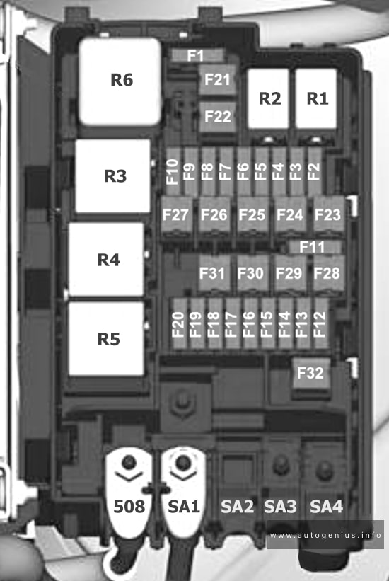
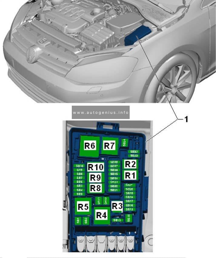
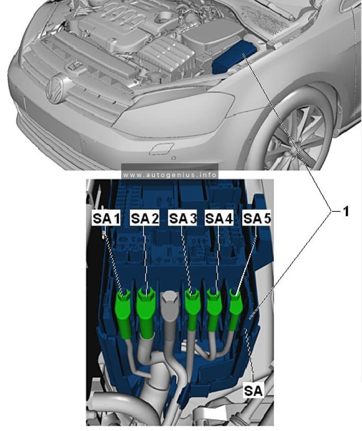
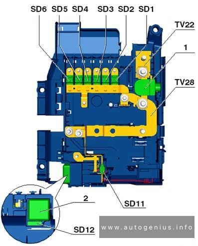
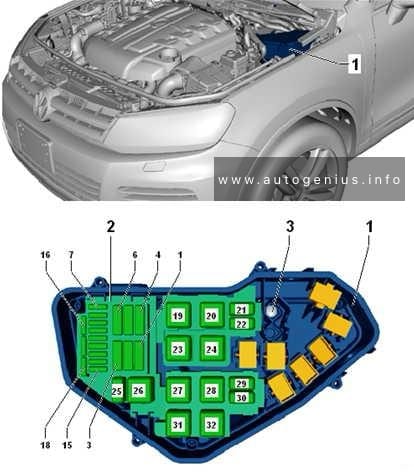
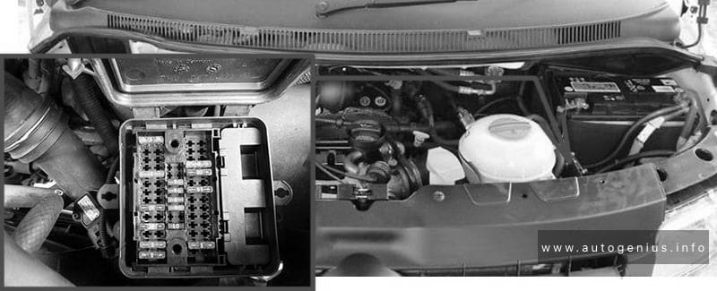
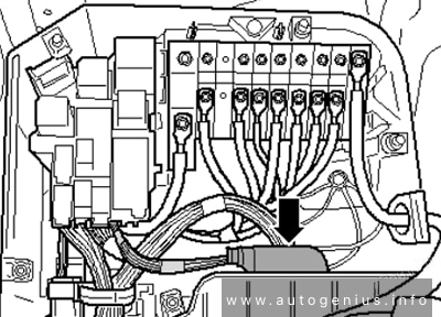
Engine Compartment Fuse Boxes
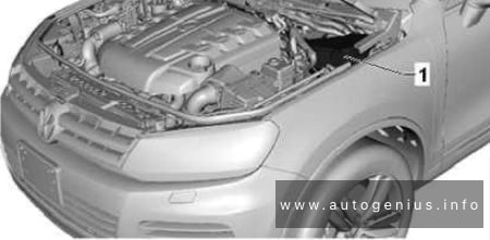
Fuse Box Location
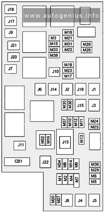
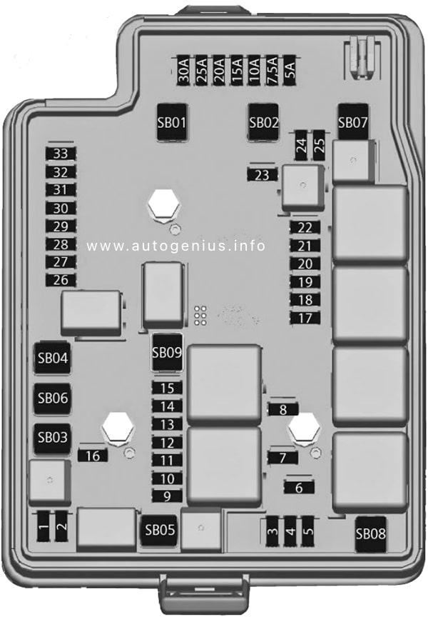
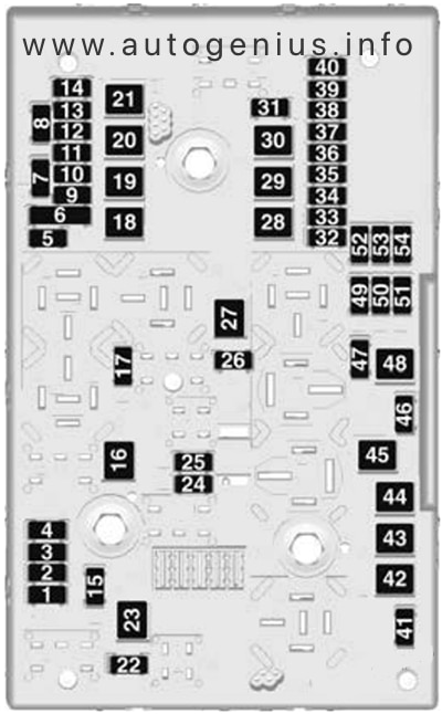
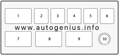
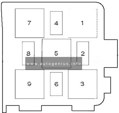
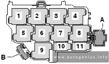
Fuse Box Diagram (-SD-)
Assignment of the fuses in the engine compartment (fuse holder D)
| № | Amps | Function/component |
|---|---|---|
| 1 | 5A | Radiator fan control unit |
| 2 | 5A | Additional coolant pump relay Residual heat relay Circulation pump |
| 3 | 5A | Heater element for crankcase breather |
| 4 | 30A | 2011-2015: Voltage stabiliser (models with stop/start system) Control unit with display for radio and navigation system (models with stop/start system) Radio (models with stop/start system) Fuse 18 on fuse holder B (models with stop/start system) Fuse 15 on fuse holder C (models with stop/start system) Fuse 16 on fuse holder C(models with stop/start system) |
| 5 | 15A | Mechatronic unit for dual clutch gearbox Selector lever lock solenoid Selector lever |
| 6 | 30A | ABS control unit |
| 7 | 7,5A | Washer pump Windscreen and rear window washer pump |
| 8 | – | – |
| 9 | 5A | Engine control unit |
| 10 | 5A | Secondary air pump relay (for engine code AXA) Activated charcoal filter system solenoid valve 1 (for engine code AXA) |
| 10 | 15A | Charge pressure control solenoid valve (for engine codes CAAA, CAAB, CAAC, CAAD, CAAE, CCHA, CCHB, CFCA) Exhaust flap valve (for engine code CFCA) Exhaust gas recirculation cooler change-over valve (for engine codes CAAA, CAAB, CAAC, CAAD, CAAE, CCHA, CCHB, CFCA) |
| 10 | 10A | Charge pressure control solenoid valve (for engine code CJKA) Activated charcoal filter system solenoid valve 1 (for engine code CJKA) Inlet camshaft control valve 1 (for engine code CJKA) Turbocharger air recirculation valve (for engine code CJKA) Intake manifold flap valve (for engine code CJKA) |
| 11 | 30A | Headlight dipper/flasher switch Headlight main beam relay |
| 12 | 10A | Fuel pressure regulating valve (for engine codes CAAA, CAAB, CAAC, CAAD, CAAE, CCHA, CCHB, CFCA) Fuel metering valve (for engine codes CAAA, CAAB, CAAC, CAAD, CAAE, CCHA, CCHB, CFCA) |
| 13 | 10A | 2010-2011: Left gas discharge light control unit |
| 14 | 5A | Fuel pump relay (for engine codes CAAA, CAAB, CAAC, CAAD, CAAE, CCHA, CCHB, AXA, CFCA) Electric fuel pump 2 relay (for engine codes CAAA, CAAB, CAAC, CAAD, CAAE, CCHA, CCHB, CFCA) |
| 15 | 10A | Reversing light switch |
| 16 | 5A | Brake light switch Air mass meter (for engine code AXA) |
| 17 | 5A | TCS and ESP button Tyre pressure monitor display button ABS control unit |
| 18 | 5A | Power steering control unit |
| 19 | 5A | Clutch pedal switch Clutch position sender Air mass meter (for engine codes CAAA, CAAB, CAAC, CAAD, CAAE, CCHA, CCHB, CFCA) |
| 20 | 5A | Engine control unit Air mass meter (for engine code CJKA) |
| 21 | 5A | Exhaust gas recirculation valve (for engine code AXA) |
| 22 | 10A | Injector, cylinder 1~4 (for engine code AXA) |
| 23 | 10A | 2010-2011: Right gas discharge light control unit |
| 24 | 5A | Mechatronic unit for dual clutch gearbox Selector lever |
| 25 | 30A | Engine control unit (for engine code AXA) Ignition transformer (for engine code AXA) |
| 25 | 20A | Actuator 1~8 for camshaft adjustment (for engine code CJKA) |
| 26 | 5A | 2010-2011: Front left headlight |
| 27 | 10A | Continued coolant circulation pump (for engine codes CAAA, CAAB, CAAC, CAAD, CAAE, CCHA, CCHB, CFCA) |
| 28 | 15A | Treble tone horn (for models with taxi equipment) |
| 29 | 5A | 2010-2011: Front right headlight |
| 30 | 20A | Fuel pump relay (for engine codes CAAA, CAAB, CAAC, CAAD, CAAE, CCHA, CCHB, CFCA) Fuel system pressurisation pump (for engine codes CAAA, CAAB, CAAC, CAAD, CAAE, CCHA, CCHB, CFCA) Electric fuel pump 2 relay (for engine codes CAAA, CAAB, CAAC, CAAD, CAAE, CCHA, CCHB, CFCA) Supplementary fuel pump (for engine codes CAAA, CAAB, CAAC, CAAD, CAAE, CCHA, CCHB, CFCA) Fuel system pressurisation pump (for engine code AXA) Fuel pump control unit (for engine code CJKA) Fuel system pressurisation pump (for engine code CJKA) |
| 31 | 15A | Lambda probe heater Lambda probe 1 heater after catalytic converter (for engine code AXA, CJKA) |
| 32 | 5A | Electric fuel pump 2 relay (for engine code AXA) |
| 32 | 30A | Engine control unit (for engine codes CAAA, CAAB, CAAC, CAAD, CAAE, CCHA, CCHB, CFCA) |
| 32 | 30A | Engine control unit (for engine code CJKA) Ignition coil 1~4 with output stage (for engine code CJKA) |
| 33 | 5A | Automatic glow period control unit (for engine codes CAAA, CAAB, CAAC, CAAD, CAAE, CCHA, CCHB, CFCA) Fuel shut-off valve switch-off relay (for engine code CJKA) Additional coolant pump relay Coolant pump relay (for engine code CJKA) Continued coolant circulation pump (for engine code CJKA) |
| 34 | 5A | Onboard supply control unit |
| 35 | 15A | Fuel shut-off valve switch-off relay (for engine code CJKA) Fuel pressure regulating valve (for engine code CJKA) |
| 35 | 5A | Battery monitor control unit (models with stop/start system) |
| 36 | 30A | Starter (models without stop/start system) Starter inhibitor relay (models without stop/start system) |
| 36 | 5A | Data bus diagnostic interface (models with stop/start system) |
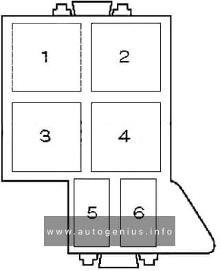
High power fuses (-SA-)
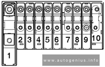
| № | Amps | Function/component |
|---|---|---|
| 1 | 175A/225A | Alternator |
| 2 | 125A | X-contact relief relay Positive connection 2 (30), in main wiring harness Positive connection 5 (30), in main wiring harness Positive connection 6 (30), in main wiring harness Positive connection 7 (30), in main wiring harness Positive connection 8 (30), in main wiring harness Positive connection 9 (30), in main wiring harness Fuse 9 on fuse holder B Fuse 14 on fuse holder B |
| 3 | 50A/100A | Second battery charging circuit relay Positive connection 14 (30), in main wiring harness Positive connection 15 (30), in main wiring harness |
| 4 | 70A | Positive connection (30), in engine compartment wiring harness |
| 5 | 50A | ABS control unit fuse 1 Fuse 6 on fuse holder D |
| 6 | 50A/60A | Automatic glow period control unit Secondary air pump relay |
| 7 | 100A | Radiator fan control unit |
| 8 | 40A/50A/100A | Positive connection 1 (30), in interior wiring harness Positive connection 2 (30), in interior wiring harness Fuse 9 on fuse holder F Fuse 14 on fuse holder F Fuse 22 on fuse holder F Fuse 23 on fuse holder F Fuse 24 on fuse holder F |
| 9 | 100A | Positive connection (30), in main wiring harness Positive connection 3 (30), in main wiring harness |
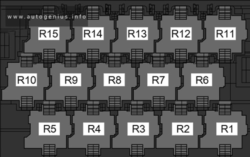
Relay carrier electronics box (8-pin)
| № | Amps | Function/component |
|---|---|---|
| A | – | – |
| B | 40A | ABS control unit |
WARNING: Terminal and harness assignments for individual connectors will vary depending on vehicle equipment level, model, and market.