Vauxhall Grandland (2017 – 2021) – fuse and relay box diagram
Year of production: 2017, 2018, 2019, 2020, 2021, 2022, 2023, 2024
The Opel Grandland X was produced from 2017 to 2024 and underwent a restyling during its production run. It is also known as the Vauxhall Grandland. In this post, you’ll find detailed information about the fuses and relays in the Grandland, including fuse box diagrams, their locations.
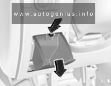
Passenger compartment fuse box
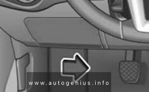
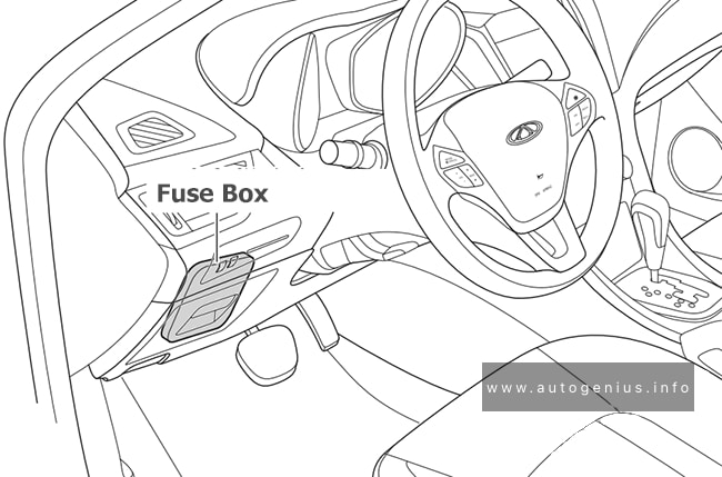
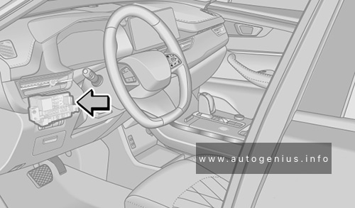
Fuse Box Location
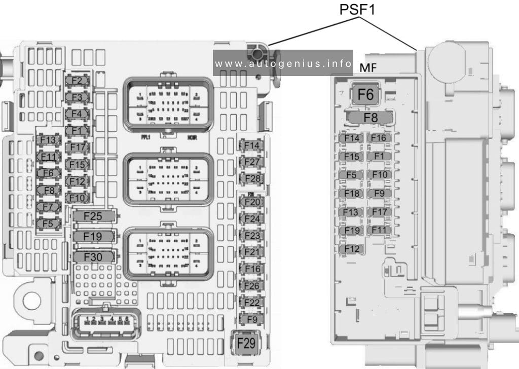
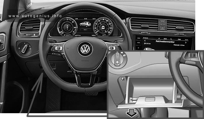
The main fuse box is located on the left side at the bottom of the instrument panel.

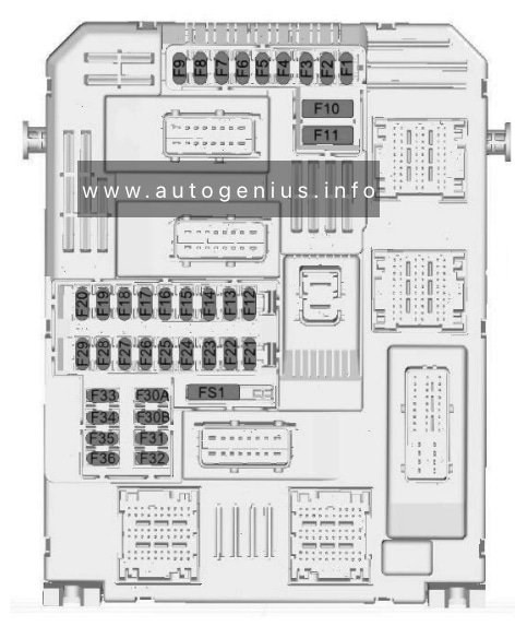
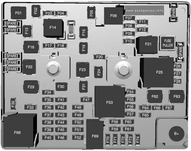
Fuse Box Diagram

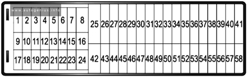
Type 1
Assignment of the fuses in the passenger compartment (type 1)
| № | Description |
|---|---|
| 1 | Interior mirror / Electric power steering wheel / Selective drive control / Radar / Diesel exhaust system |
| 3 | Trailer Position Control Module |
| 4 | Signal |
| 5 | Window washer (front/rear) |
| 6 | Window washer (front/rear) |
| 7 | Rear socket |
| 8 | Rear wiper |
| 10 | Door lock/rear door lock |
| 11 | Door lock/rear door lock |
| 12 | Stop-Start System / Diagnostic Connector Module / Brake System |
| 13 | Infotainment system / Climate control system |
| 14 | Alarm siren |
| 15 | Climate control system |
| 16 | Stop-start/Brake system |
| 17 | Instrument panel |
| 18 | Parking assistant |
| 19 | Steering Column Electrical System / Steering Wheel Controls |
| 21 | Anti-theft alarm |
| 22 | Camera / Rain sensor / Automatic lighting control |
| 23 | Seat belt reminder |
| 24 | Automatic Transmission /Advanced Parking Assist / Panoramic View System |
| 25 | Air bag |
| 26 | Electronic stability control |
| 27 | Anxiety |
| 28 | OnStar or BTA module |
| 29 | Infotainment system |
| 32 | Cigarette lighter/ front socket |
| 34 | Heated rear window / Heated windshield / Inductive charging |
| 35 | Light switch/ diagnostic connector module |
| 36 | Lighting |
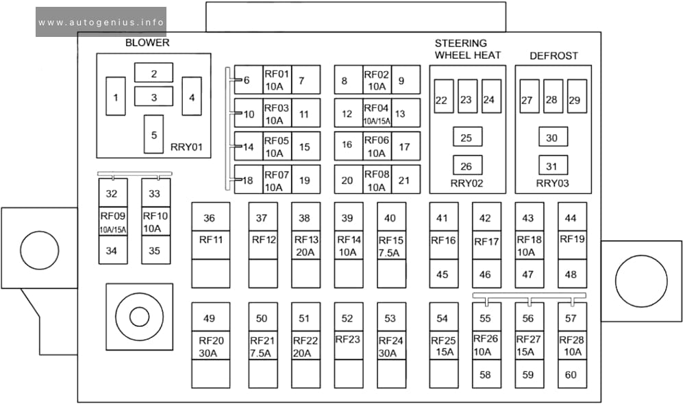
Type 2
Assignment of the fuses in the passenger compartment (type 2)
| № | Amp | Description |
|---|---|---|
| 1 | 3 | Electronic Key System – Anti-Theft Alarm – Ignition Switch |
| 2 | 3 | Steering angle sensor |
| 3 | 3 | Instrument connector – comelec system |
| 4 | 7,5 | Instrument connector – Diagnostic connector – Double brake pedal contactor – Central voltage maintainer |
| 5 | 5 | Multi-function screen – Rear view camera – Parking assistance computer – Transmission control module |
| 6 | 15 | Reserve |
| 7 | 10 | Audio Amplifier |
| 8 | 20 | Rear window wiper |
| 9 | 5 | “Ground” of front and rear lamps |
| 10 | 30 | Drive of central and internal locks of front and rear doors + fuel tank flap |
| 11 | 30 | Power supply for drives of front and rear external and internal locks |
| 12 | 3 | Security alarm |
| 13 | 3 | Additional heater activation module |
| 14 | 15 | |
| 15 | 5 | |
| 16 | 5 | Electric power steering |
| 17 | 10 | 12B connector in trunk or cargo area |
| 18 | 5 | Autonomous telematics unit – OnStar or BTA module |
| 19 | 5 | |
| 20 | 15 | Interior fuse box 3 |
| 21 | 3 | Indoor lighting – Charger for portable lamp – Individual lamps |
| 22 | 3 | Glove box lighting – Individual lamps |
| 23 | 3 | Blind Spot Warning System – Exterior Mirror Adjustment – Inductive Charging |
| 24 | 5 | Common Connection Unit – Steering Wheel Communication Module CV00 |
| 25 | 5 | Switch for headlight range control – rear view mirror |
| 26 | 3 | Instrument Connector – Driver and Passenger Seat Belt Display |
| 27 | 3 | Rain and light sensor – Steering column switch |
| 28 | 10 | Front center element – Multiplex front panel – Car radio – Display of information in the driver’s field of vision |
| 29 | 5 | Motor switching unit (PSF1) |
| 30 | 15 | Audio system |
| 31 | 5 | Airbag control unit |
| 32 | 5 | Reserve |
| 33 | 15 | Cigarette lighter or instrument panel 12V connector |
| 34 | 3 | Trailer connection box |
| 35 | 5 | Instrument panel control computer |
| 36 | 20 | Car radio |
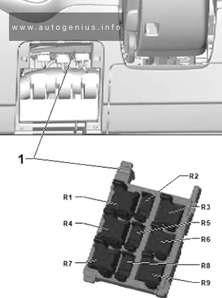
| Relay | ||
| R1 | Power + accessories | |
| R2 | Power supply “plus” CAN “Comfort” | |
| R3 | Rear window wiper | |
| R4 – R9 | Electric motors for driving front and rear external and internal locks | |
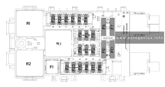
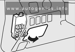
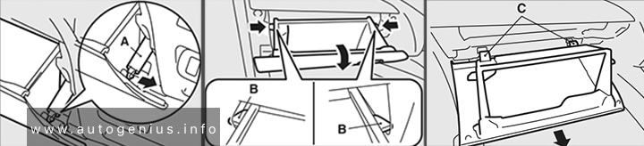
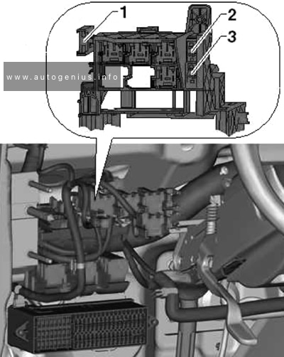
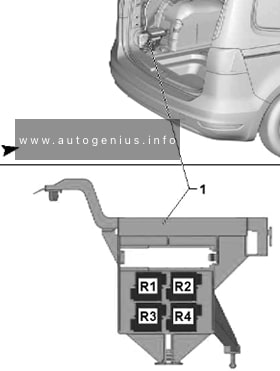
Fuse and relay box
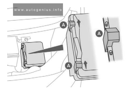
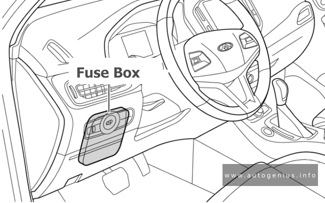
Fuse Box Location
This block is located behind the main fuse box and is mounted on the front wall of the passenger compartment.
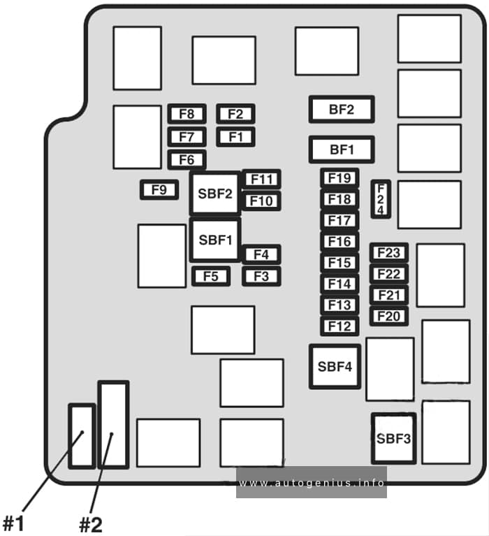
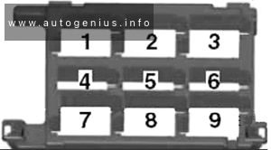
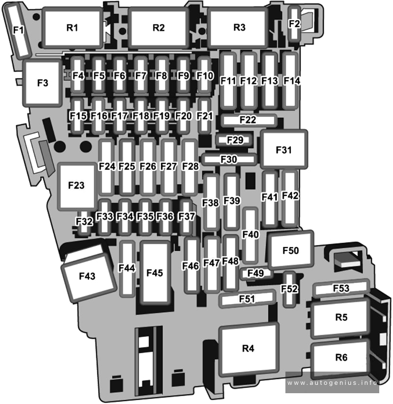
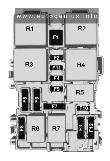
Type 1
Fuse Box Diagram

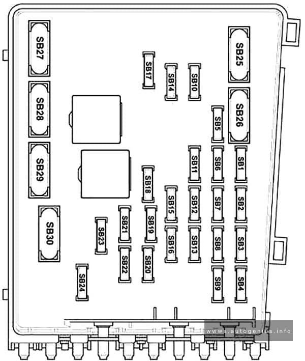
Assignment of the relays in the passenger compartment (behind main fuse box) type 1
| Number | Amp | Description |
| F1 | 40 | Heated rear window |
| F2 | 7,5 | Electric mirrors |
| F3 | 20 | Relay socket 230A ECO: Power front windows |
| F4 | 15 | Trunk socket 12V |
| F5 | 30 | Rear window lift motors |
| F6 | 30 | Electric motors for front window lifters |
| F7 | 25 | Heated seats |
| F8 | 20 | Additional air fan for rear seats |
| F9 | 30 | Power tailgate unit (6290) |
| F10 | 40 | Left seat belt reel |
| F11 | 5/20 | Trailer switching unit 7/13 channels |
| F12 | 30 | Electrically adjustable driver’s seat |
| F13 | 30 | Hatch 40A Right seat belt reel |
| F14 | 30 | Power passenger seat |
| F15 | 30 | Sunroof |
| F16 | 10 | Rear view mirror unit |
| F17 | 10 | Lighting and mirror memory unit |
| F18 | 25 | Radio Amplifier |
| F19 | 30 | Reserve |
| F20 | 3 | Electric tailgate drive unit (6290) |
| F21 | 3 | Trunk switch (6292) |
| F22 | 20 | Reserve |
| F23 | 3 | Trailer connection box |
| Relay | ||
| R1 | 230A connector | |
| R2 | Trunk socket 12V | |
| R3 | Heated rear window and exterior mirrors | |
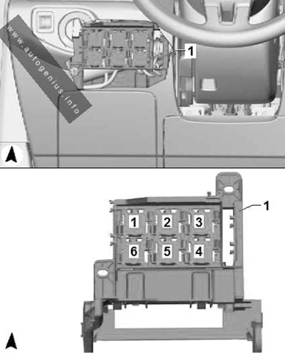
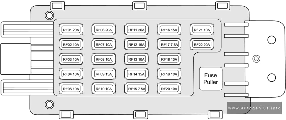
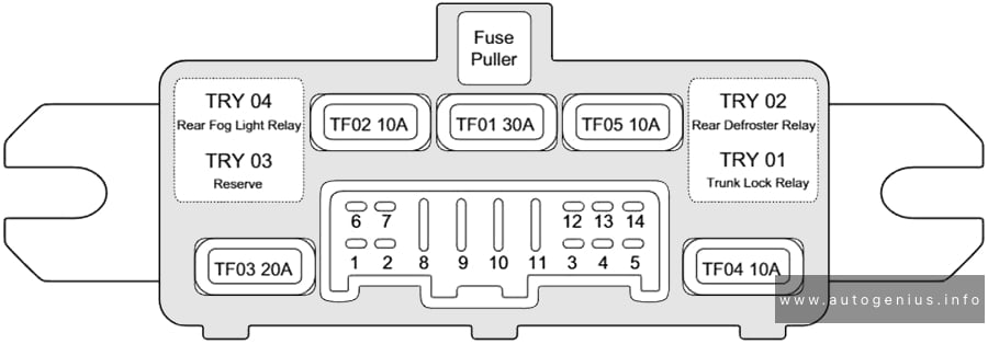
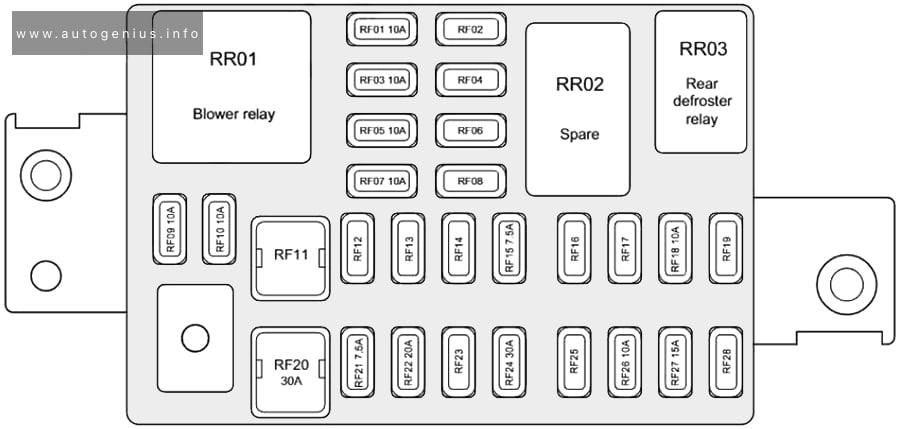
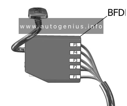
Type 2
Fuse Box Diagram
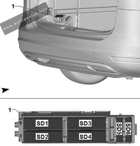
Assignment of the relays in the passenger compartment (behind main fuse box) – type 2
| Number | Amp |
Description |
| F1 | 40 | Heater / rear window defroster |
| F2 | 10 | Heated exterior side mirrors |
| F3 | 10 | Electric windows – front |
| F4 | 10/15 | Folding side mirrors / Adjustable outside mirrors |
| F5 | 30 | Power windows – rear |
| F6 | Seat heating | |
| F7 | – | |
| F8 | Fuse Box (Right Side of Dashboard) | |
| F9 | – | |
| F10 | 20 | Heated front seats |
| F11 | 20 | Front seat massage function |
| F12 | Empty (reserved) | |
| Relay | ||
| R01 | Seat heating relay | |
| R02 | Power window relay | |
| R03 | Rear window defroster/heater relay | |
| R04 | – | |
| R05 | – | |
| R06 | – | |
| R07 | – | |
Engine compartment fuse box
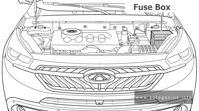
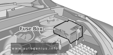
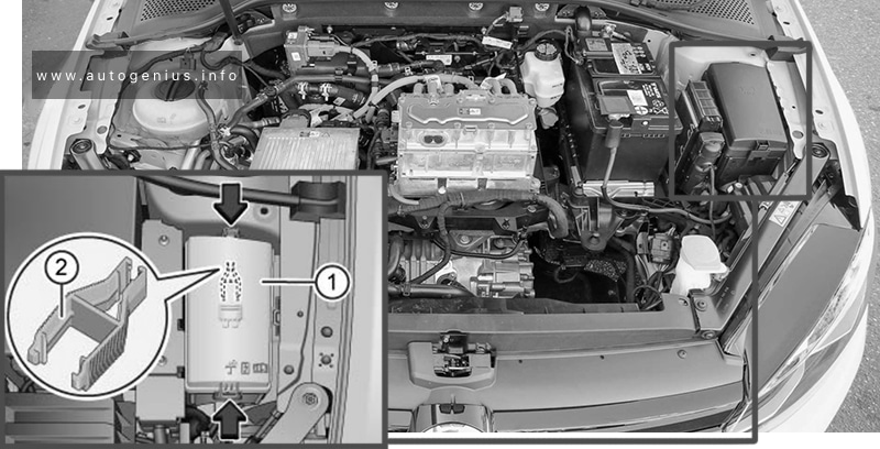
Fuse Box Location
In the engine compartment, under the hood, on the left side, next to the battery, there is a fuse and relay box.

Type 1
Fuse Box Diagram

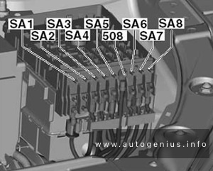
Assignment of the fuses in the engine compartment (type 1)
| № | Amp | Description |
|---|---|---|
| 1 | 15 | Engine control, Pressure conversion relay activation (1032) – Diesel injectors |
| 2 | 5 | Electric fan relay control |
| 3 | 5 | Starter/Alternator K207 Battery Control Module |
| 4 | 5 | SCR injector, P17 Information display module |
| 5 | 15 | Diesel fuel booster pump, Fuel pump |
| 6 | 20 | Engine control, controlled fuel pump |
| 7 | 10 | Solenoid valve for diesel fuel supply control pump – Proportional solenoid valve TGV |
| 8 | 10 | Water in diesel fuel sensor – Oil pump electra valve – NOx sensor DW10F |
| 9 | 10 | Electric ignition switch P16 Instrument panel |
| 10 | 5 | Start/Stop relay KL9 |
| 11 | 15 | Switching and protection unit control – Fuel additive pump – Traction control switch |
| 12 | 5 | Reserve |
| 13 | 5 | Network voltage maintenance device |
| 14 | 25 | A/C compressor solenoid |
| 15 | 5 | Power Steering Computer, Diagnostic Connector, Vehicle Distance Assist (Radar) |
| 16 | 20 | Rear air conditioning unit pump |
| 17 | 10 | Intelligent Switching Box |
| 18 | ||
| 19 | 30 | Reserve |
| 20 | 15 | Power supply for front and rear windshield washer pumps |
| 21 | 20 | Headlight washer pump |
| 22 | 15 | Horn |
| 23 | 15 | Right headlights |
| 24 | 15 | Left headlights |
| 25 | 30 | Reserve |
| 26 | ||
| 27 | 5 | Reserve |
| 28 | 5 | |
| 29 | 30 | Starter |
| 30 | 30 | Diesel fuel heater |
| MF1 | 5 | With controlled air intake module |
| MF11 | 5 | Reserve |
| MF12 | 15 | Automatic transmission computer AX6 |
| MF13 | 20 | Heater (coolant and interior heating) |
| MF14 | Comelec automatic transmission | |
| MF15 | Reserve | |
| MF16 | Reserve | |
| MF17 | Reserve | |
| MF18 | 5 | Double Brake Pedal Contactor |
| MF19 | 5 | Reserve |
| Relay | ||
| R1 | Diesel engine control computer | |
| R2 | Switching off the engine communication unit | |
| R3 | Switching off the engine communication unit | |
| R4 | Engine computer, central voltage maintainer, electric fan, reversing generator | |
| R5 | Fuel Pump – NOX Sensor | |
| R6 | Electrical power from the ignition switch | |
| R7 | Starter | |
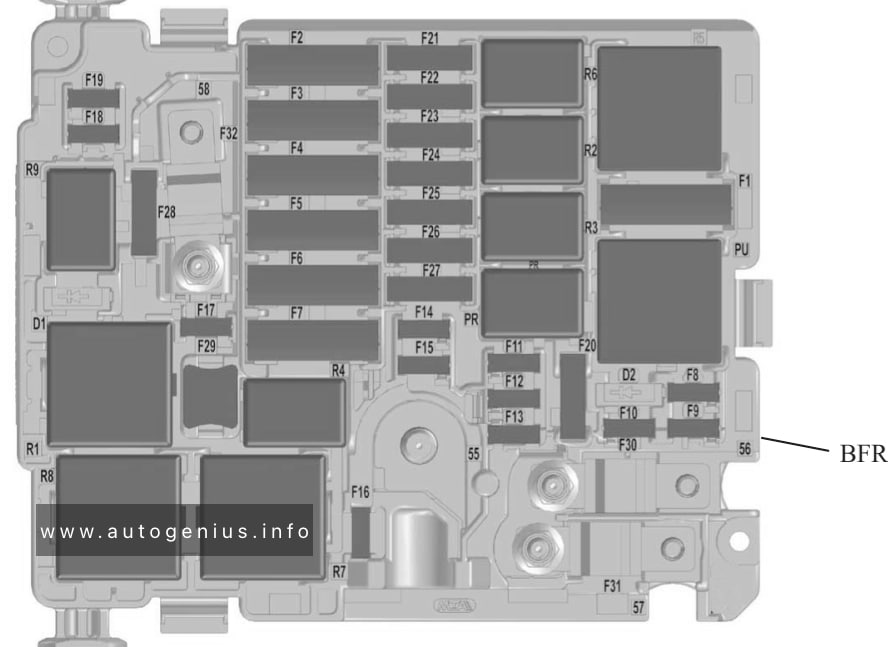
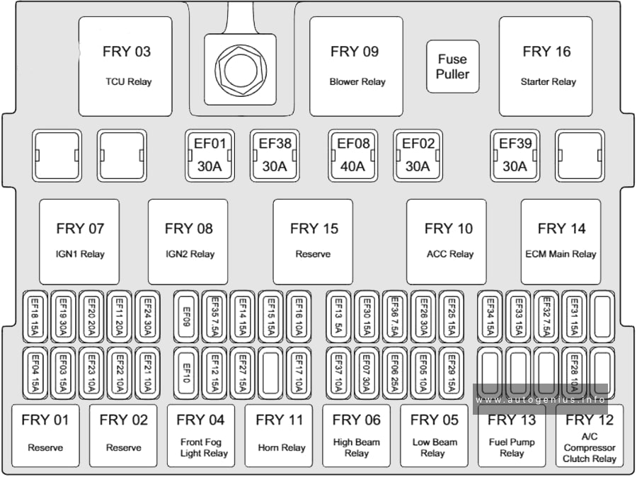
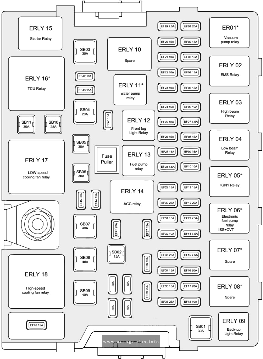
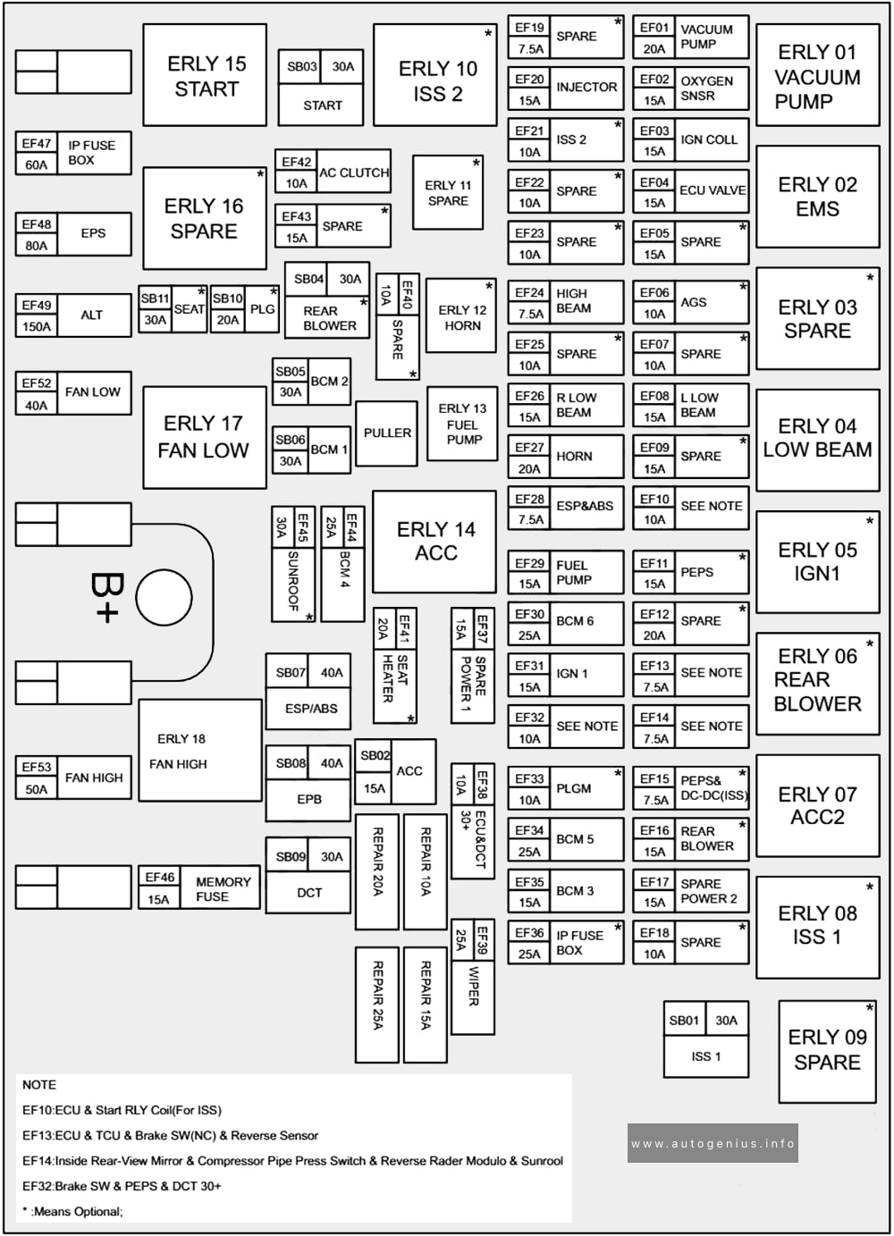
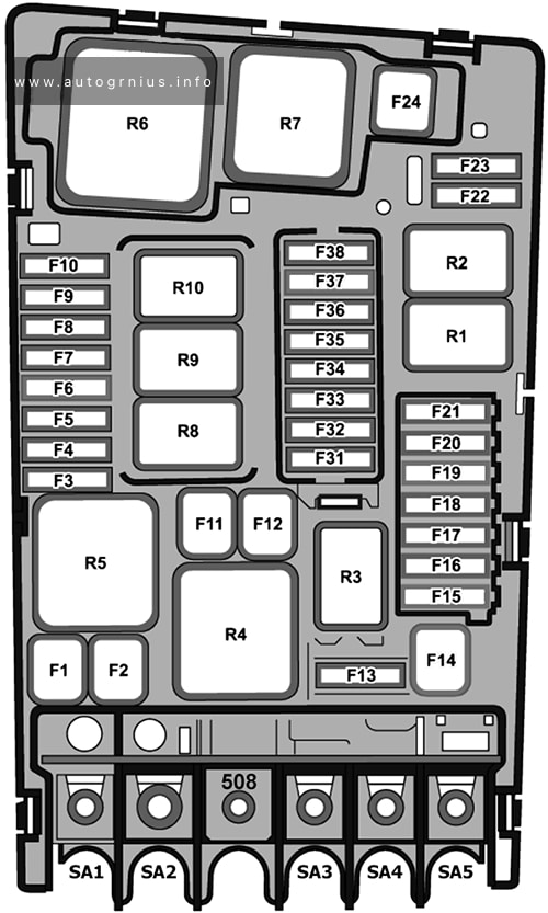
Type 2
Fuse Box Diagram

Assignment of the fuses in the engine compartment (type 2)
| № | Amp | Description |
|---|---|---|
| F1 | 40 | Air conditioner fan |
| F2 | 60 | Computer ABS/ESP system |
| F3 | 80 | Interior fuse box 3 |
| F4 | 30 | Computer ABS/ESP system |
| F5 | 50 | Intelligent Switch Unit (Right turn signals, front right side marker lights, right brake lights, left reverse lights, right fog lights.) |
| 20 | Heated windshield | |
| F6 | 60 | Two-speed cooling fan control unit (GMV) 20A BVA AxN8 calculator – BVA Ax6III calculator (thermal) |
| F7 | 70 | Intelligent Switching Box |
| F8 | 15 | Engine Control Fuel Pump, Pilot Controlled Thermostat – Oil Pump Solenoid Valve (EC Flush – Electrical Solenoid Valve – Intake Air Flow Meter – Oxygen Sensors (EP6FADTX), Pilot Controlled Thermostat – Switchable Water Supply, Electrical Solenoid Valve (EP6FDT) |
| 20 | Computer engine (for EB2DT or EP6FDT) l Controlled booster pump (for DV6F or DW10F) | |
| F9 | 15 | 15A Piloted lift pump (DW10F), intake and exhaust valves v solenoid valves – Piloted thermostat – Oil pump solenoid valve (EC flush – Electrical solenoid valve – Intake air flow meter – Oxygen sensors (EP6FADTX), Piloted thermostat – Switchable Water Supply Electric Solenoid Valve (EP6FDT) |
| F10 | 15 | 15A Engine Computer – Diesel Flow Control Pump Solenoid – Turbocharger Pressure Control Solenoid Valve (DV5R and DW10F) – Thermostat S (DV5R) – Purge Heater – Adjustable Intake and Exhaust Valve Solenoid Valves (EP6FADTX) – Cylinder Flush – Oxygen Sensors Raised (EB2ADTS ) ) |
| F11 | 20 | 20A Engine computer |
| F12 | 5 | Instruments – GMV relay – Istars – DMTC, electric water cooling with turbocharging (EB2ADTS and EP6FADTX), intelligent service unit (EP6FADTX) |
| F13 | 5 | Intelligent Switch Box |
| F14 | 5 | Battery charge level block |
| F15 | 20 | Electrically heated windshield |
| F16 | 15 | Fog lights |
| 10 | Daytime running lights | |
| F17 | 10 | GMP relay diagnostics BFRM – BSI1 – Engine computer – Lower Nox sensor (injectors DV5R and DW10 (DV5R) |
| F18 | 10 | Right headlights high beam |
| F19 | 10 | Left headlights high beam |
| F20 | 30 | Engine computer l Charge pump (for ER6EDT) – ignition coils (EB2ADTS and EP6FADTX) |
| F21 | 30 | Starter |
| F22 | 40 | Reserve – Taxi |
| F23 | 40 | Starter/Alternator |
| F24 | 40 | Fuse box in passenger compartment 5 |
| F25 | 40 | Interior fuse box 3 |
| F26 | 15/20 | Heater |
| F27 | 25 | Intelligent Switching Unit (Right Low Beam Headlight – Right Reversing Lights – Left Fog Lights – Left Rear Parking Lights – Third Brake Light.) |
| F28 | 30 | Power supply for urea pump and urea tube heating resistor (UCE or DV5R) – Nox sensor (DW10F) – Engine computer (EP6FADTX) – (BlueInjection, AdBlue) |
| F29 | 40 | Windshield wiper |
| F30 | 80 | Pre-heating unit |
| F31 | 80 | Switching and protection unit |
| F32 | 80 | Power steering, Left low beam headlight – Static turn lights – Side turn indicators – Left turn indicators – Front left and rear right side lights – Left brake lights – License plate lights. |
| Relay | ||
| R1 | Engine control computer / Euro6 diesel (SCR module power supply) | |
| R2 | Air Conditioning Compressor/Heated Windshield | |
| R3 | Starter / thermal preconditioning | |
| R4 | Fog lights/daytime running lights | |
| R5 | Air conditioner fan | |
| R6 | Starter | |
| R7 | Front wiper | |
| R8 | Front wiper | |
| R9 | ||
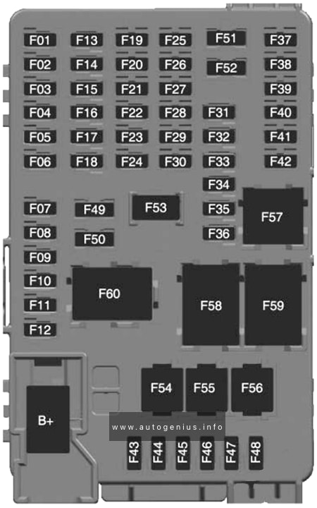
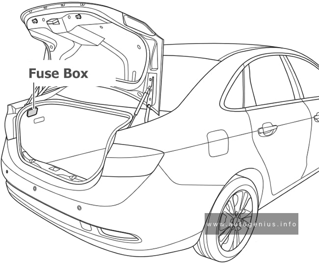
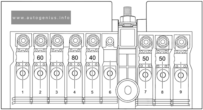
Battery fuse box
Fuse Box Location
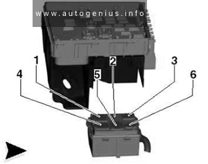
A high power fuse box is attached to the positive terminal of the battery.
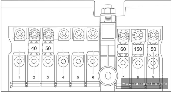
Fuse Box Diagram
Assignment of the fuses in battery fuse box
| № | Amp | Description |
|---|---|---|
| 1 | 60 | Electrical control unit for two-speed fan motor |
| 2 | 100 | Fuse box |
| 3 | 80 | Power steering |
| 4 | 80 | Interior fuse box |
| 5 | 80 | Interior fuse box |
WARNING: Terminal and harness assignments for individual connectors will vary depending on vehicle equipment level, model, and market.