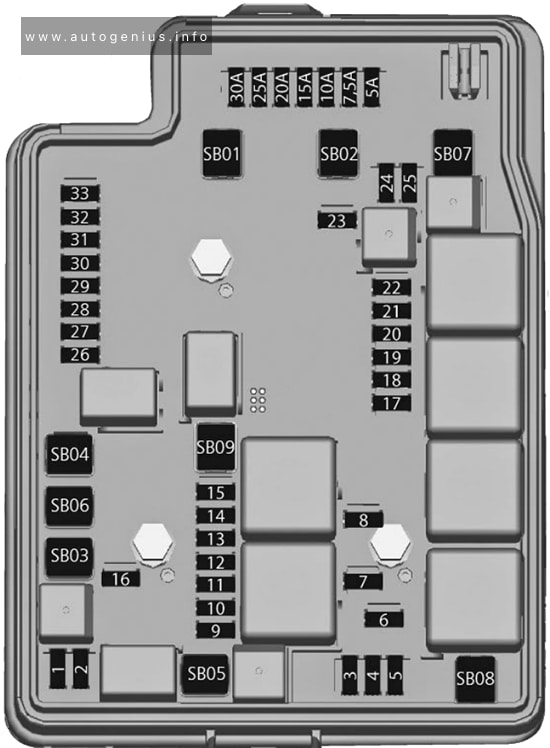
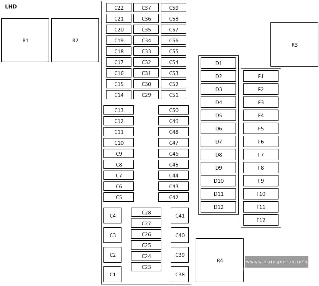
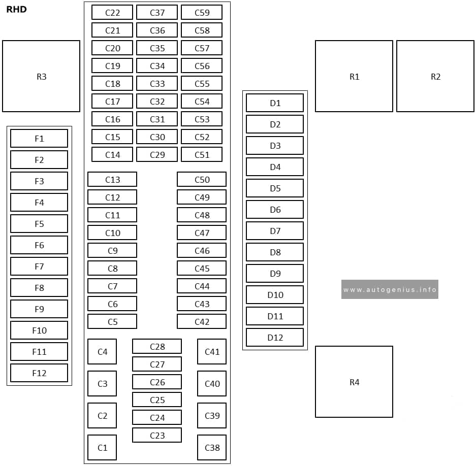
| № |
Amps |
Function/component |
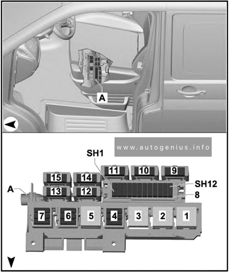
| C1 |
40 A |
Sender for front Bitron blower regulation
Fresh air blower
Auxiliary coolant heater relay
Fresh air blower switch
Air conditioning system control unit |
| C2 |
60 A |
X-contact relief relay
Positive connection (X), in interior wiring harness |
| C3 |
30 A |
Onboard supply control unit |
| C4 |
40 A |
Window regulator thermal fuse -S43-
Fuses on fuse holder C: #18, 22, 57, 58, 59
Fuses on fuse holder D: #1-7, 9
Fuses in fuse holder F: 1, 2, 3, 5, 6, 7, 9, 10 |
| C5 |
7.5 A / 15 A |
Onboard supply control unit |
| C6 |
30 A |
Onboard supply control unit |
| C7 |
30 A |
Terminal 15 voltage supply relay
Positive connection 2 (15) in interior wiring harness |
| C8 |
5 A |
Light switch |
| C9 |
5 A |
Steering column combination switch
Headlight dipper and flasher switch
Onboard supply control unit |
| C10 |
30 A |
Control unit 1 for information electronics
Radio |
| C11 |
30 A |
Onboard supply control unit |
| C12 |
15 A |
Onboard supply control unit |
| C13 |
30 A |
Onboard supply control unit |
| C14 |
5 A |
Differential lock control unit
Isolation relay for powertrain CAN bus
16-pin connector (diagnostics) |
| C15 |
7.5 A |
Fresh air and air recirculation flap switch
Climatronic control unit
Air conditioning system control unit |
| C16 |
5 A |
Onboard supply control unit |
| C17 |
10 A |
Onboard supply control unit |
| C18 |
7.5 A |
USB hub
Two-way signal amplifier for mobile telephone/data services
Storage compartment with interface for mobile telephone
Reversing camera |
| C19 |
7.5 A |
Positive connection, in roof wiring harness |
| C20 |
7.5 A |
Positive connection 1 (30a) in main wiring harness |
| C21 |
10 A |
Onboard supply control unit
Relay 1 for ignition bypass
Interface for external use 6-pin connector
X-contact relief relay |
| C22 |
5 A |
Dash panel insert |
| C23 |
5 A |
Interface for external use 10-pin connector
Starter inhibitor relay |
| C23 |
30 A |
Starter
Starter inhibitor relay
Starter relay 1
Starter relay 2 |
| C24 |
7.5 A |
Fresh air and air recirculation flap switch
Rear fresh air blower switch
Fresh air blower isolation relay |
| C25 |
10 A |
Rear window wiper motor
Rear left wing door window wiper motor
Rear right wing door window wiper motor
Left washer jet heater element
Right washer jet heater element |
| C26 |
5 A |
Terminal 75 voltage supply relay 1
Onboard supply control unit
Interface for external use 6-pin connector |
| C26 |
15 A |
Interface for external use 10-pin connector |
| C27 |
25 A |
Heated front seats control unit |
| C28 |
5 A |
Auxiliary coolant heater relay |
| C29 |
10 A |
Airbag control unit
Warning lamp for airbag deactivated on front passenger side |
| C30 |
10 A |
Mirror adjustment switch
Headlight range control regulator
Accident data recorder button
High-pressure sender
Air quality sensor
Oil level and oil temperature sender
Trailer detector control unit
Parking aid control unit
Headlight range control unit
Accident data memory
Front left headlight
Front right headlight
4-pin connector
10-pin connector
Diagnostic connection
Left headlight range control motor
Right headlight range control motor
Coolant shut-off valve relay
Climatronic coolant shut-off valve
Voltage supply relay 2
Parking aid control unit |
| C31 |
– |
not assigned |
| C32 |
7.5 A |
Light switch
Operating and display unit for camping equipment
Accident data recorder button
Start/Stop operation button
Tachograph
Steering angle sender
Electronically controlled damping control unit
Multifunction steering wheel control unit
Onboard supply control unit
Accident data memory
Main beam assist control unit
Dash panel insert
Automatic anti-dazzle interior mirror
Headlight dipper and flasher switch
Onboard supply control unit |
| C33 |
10 A |
Rear differential lock switch
Vacuum switch for rear differential lock
All-wheel drive control unit
Differential lock control unit
Differential lock valve 1
Differential lock valve 2 |
| C34 |
5 A |
Operating and display unit for camping equipment
Internet access control unit
10-pin connector
Interface for external use 10-pin connector |
| C35 |
10 A |
10-pin connector
12-pin connector |
| C35 |
15 A |
Taximeter
Mirror taximeter
Taxi alarm remote control, control unit |
| C36 |
15 A |
Intermittent wiper switch
Rear wiper switch
Washer pump switch (automatic wash/wipe and headlight washer system)
Onboard supply control unit
Washer pump
Rear window wiper motor
Windscreen and rear window washer pump
Rear left wing door window wiper motor
Rear right wing door window wiper motor |
| C37 |
5 A |
Cruise control system switch
Cruise control system (CCS) SET button
Adaptive cruise control unit
Lane change assist control unit
Lane change assist control unit 2 |
| C38 |
40 A |
Ignition/starter switch |
| C39 |
20 A |
Ignition/starter switch |
| C40 |
20 A |
12 V socket 6 |
| C40 |
30 A |
Auxiliary heater relay
Fresh air blower series resistor with overheating fuse |
| C41 |
30 A |
Onboard supply control unit |
| C42 |
25 A / 30 A |
Fresh air blower isolation relay
Rear fresh air blower switch |
| C42 |
30 A |
Rear blower regulation sender
Rear fresh air blower |
| C43 |
30 A |
Control unit for reducing agent heater |
| C44 |
15 A |
Rear lid control unit |
| C44 |
20 A |
Alarm horn
Onboard supply control unit
Rear lid control unit
Left sliding door control unit
Right sliding door control unit |
| C45 |
30 A |
Amplifier |
| C46 |
20 A |
Auxiliary heater control unit |
| C47 |
25 A |
Onboard supply control unit |
| C48 |
25 A |
Sliding sunroof adjustment control unit |
| C49 |
15 A |
Cigarette lighter |
| C50 |
25 A |
Headlight washer system relay
Headlight washer system pump |
| C51 |
5 A |
Steering angle sender |
| C52 |
5 A |
Interior monitor send and receive module 1
Interior monitor send and receive module 2 |
| C53 |
5 A |
Rain and light sensor |
| C54 |
7.5 A |
Operating and display unit for camping equipment
Roof display unit
Remote control receiver for auxiliary heater
Remote control receiver for auxiliary coolant heater
Residual heat relay
Circulation pump |
| C55 |
5 A |
Operating and display unit for camping equipment
Onboard supply control unit
Roof hydraulics control unit
10-pin connector
Interface for external use 10-pin connector |
| C56 |
5 A |
Starter inhibitor relay
Engine/motor control unit
Interfacefor external use 10-pin connector
Interface for external use 10-pin connector |
| C57 |
5 A |
Operating and display unit for rear air conditioning system |
| C58 |
10 A |
Tachograph |
| C59 |
5 A |
Taximeter
Mirror taximeter |
| C59 |
10 A |
Red cross light switch
Red cross light bulb |
| C59 |
10 A |
Rotating light switch
Rotating light relay
Rotating light motor |
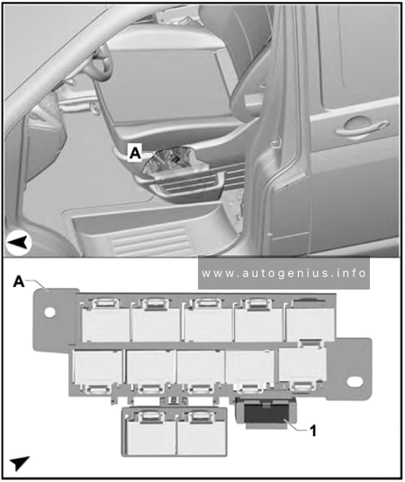
|
|
|
| D1 |
5 A |
Two-way radio button
Front interior light (door contact) button
Ignition bypass button
Button for daytime running light switch-off |
| D1 |
5 A |
Voltage supply relay 1
Voltage supply relay 2
Parking aid control unit |
| D1 |
15 A |
Interior light switch (taxi)
Taximeter
Taxi alarm remote control, control unit
Two-way radio |
| D1 |
20 A |
All-wheel drive control unit |
| D2 |
30 A |
Special vehicle control unit |
| D3 |
15 A |
Onboard charging unit
Internet access control unit |
| D3 |
15 A |
Alarm horn relay
Treble horn |
| D3 |
30 A |
Rear lid power opening control unit |
| D4 |
10 A |
Interior light relay
Switch and instrument illumination regulator |
| D4 |
15 A |
Alarm system relay 1
Onboard supply control unit
Front left headlight |
| D5 |
15 A |
Alarm system relay 1
Onboard supply control unit
Front right headlight |
| D5 |
15 A |
Electronically controlled damping control unit |
| D6 |
15 A |
Interface for external use 10-pin connector |
| D6 |
25 A |
10-pin connector |
| D7 |
5 A |
Interface for external use 10-pin connector |
| D7 |
5 A |
6-pin connector |
| D7 |
5 A |
Interior light switch (taxi)
Taxi sign switch |
| D8 |
5 A |
Accident data memory |
| D8 |
5 A |
Accident data memory
6-pin connector |
| D8 |
15 A |
Interface for external use 10-pin connector |
| D9 |
10 A |
Relay 1 for ignition bypass
Relay 2 for ignition bypass |
| D9 |
25 A |
Interface for external use 6-pin connector |
| D10 |
5 A |
Interface for external use 10-pin connector
10-pin connector |
| D11 |
10 A |
Accident data memory |
| D11 |
15 A |
Accident data memory
10-pin connector |
| D11 |
15 A |
Interface for external use 10-pin connector |
| D11 |
15 A |
Accident data memory
Interface for external use 10-pin connector |
| D12 |
3 A |
10-pin connector
Interface for external use 10-pin connector |
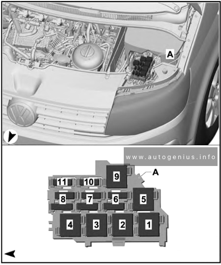
|
|
|
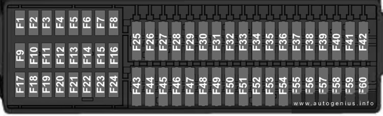
| F1 |
20 A |
All-wheel drive control unit |
| F2 |
5 A / 10 A |
Interior light relay
Switch and instrument illumination regulator |
| F3 |
30 A |
Driver seat adjustment control unit
Switch module for front passenger seat
Front passenger seat longitudinal adjustment motor
Front passenger seat front height adjustment motor
Front passenger seat rear height adjustment motor
Front passenger seat backrest adjustment motor |
| F4 |
5 A |
Emergency call module control unit and communication unit |
| F5 |
15 A |
Electronically controlled damping control unit |
| F6 |
30 A |
Driver seat adjustment control unit
Switch module for front passenger seat
Front passenger seat longitudinal adjustment motor
Front passenger seat front height adjustment motor
Front passenger seat rear height adjustment motor
Front passenger seat backrest adjustment motor |
| F7 |
5 A |
Accident data memory |
| F8 |
– |
not assigned |
| F9 |
5 A |
Diagnosis wire relay |
| F9 |
5 A |
Voltage supply relay 1
Voltage supply relay 2
Parking aid control unit |
| F10 |
30 A |
Rear lid power opening control unit |
| F11 |
20 A |
12 V socket 6 |
| F12 |
– |
not assigned |
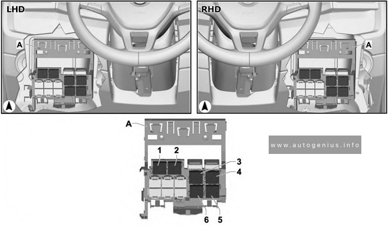
|
|
|
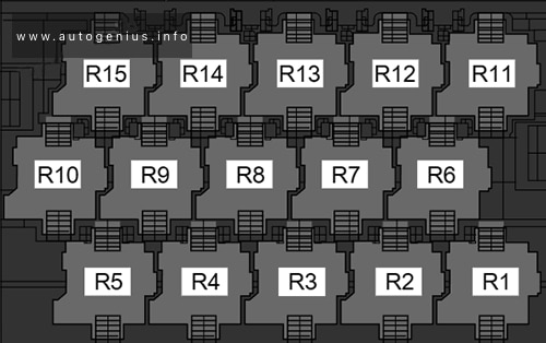
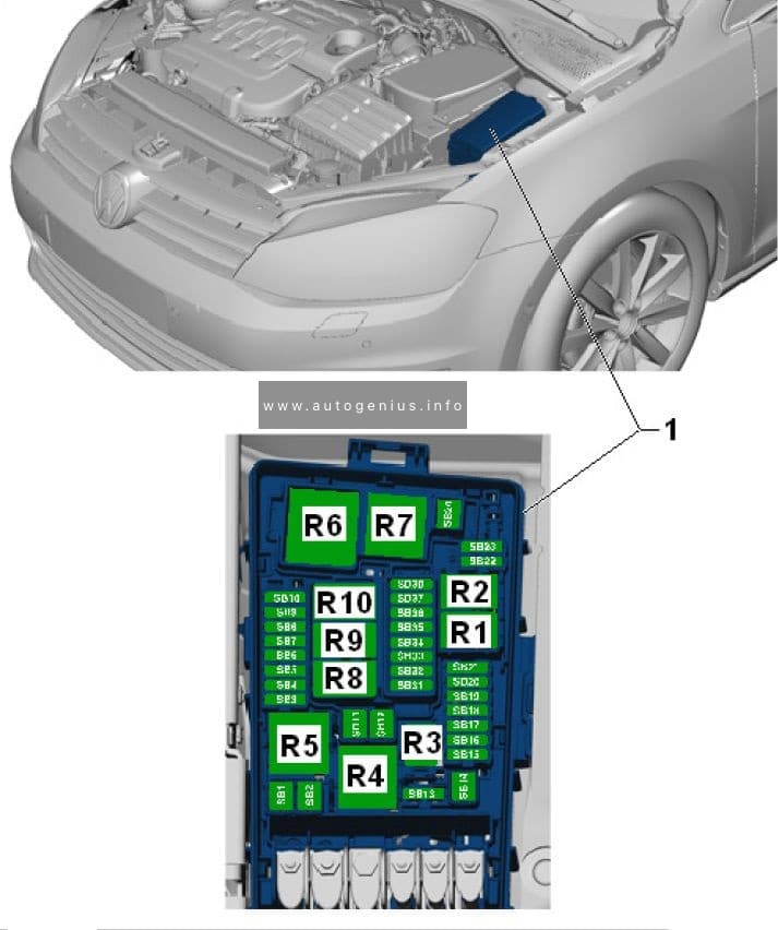
| R1 |
|
X-contact relief relay |
| R2 |
|
Diagnosis wire relay |
| R2a |
|
Voltage supply relay 1 |
| R2b |
|
Voltage supply relay 2 |
| R3 |
|
Fresh air blower isolation relay |
| R4 |
|
Terminal 15 voltage supply relay |