Chery Tiggo 7 (T15; 2016 – 2020) – fuse and relay box diagram

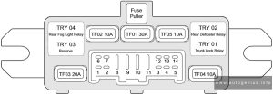
Chery Tiggo 7 (T15; 2016 – 2020) – fuse and relay box diagram

Year of production: 2016, 2017, 2018, 2019, 2020


Passenger Compartment Fuse Panel

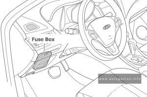
Fuse Box Location

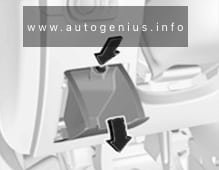
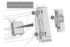
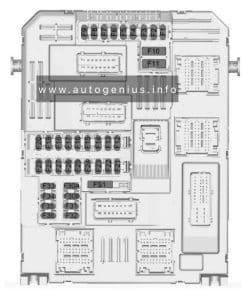
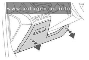
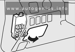
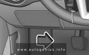
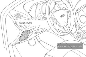
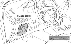
Instrument panel fuse and relay box is located on the lower left side of instrument panel.

Chery Tiggo 7 - fuse and relay box location - passenger compartment
Chery Tiggo 7 – fuse and relay box location – passenger compartment


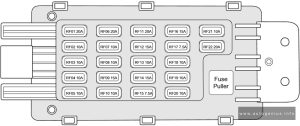
Fuse Box Diagram

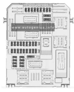
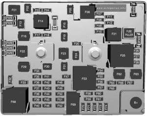
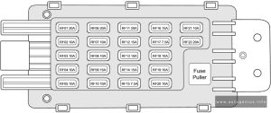
Chery Tiggo 7 - fuse and relay box diagram - passenger compartment
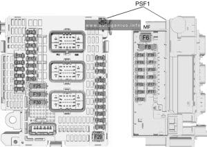
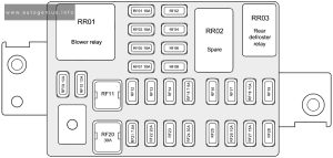
Chery Tiggo 7 – fuse and relay box diagram – passenger compartment


Assignment of the fuses in the instrument panel 

Description
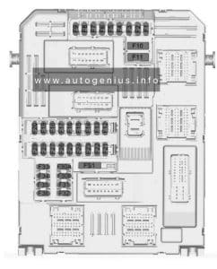
RF01 BCM
RF02
RF03 Steering Wheel Rotation Angle Sensor, EPS
RF04 Main Blind Spot Monitor Radar, Auxiliary Blind Spot Monitor Radar
RF05 Airbag Module
RF06
RF07 A/C Wire Harness Interface, Audio Head Unit, Automatic A/C Panel, Headlight Adjustment Switch, DCT Shift Mechanism
RF08
RF09 A/C Wire Harness Interface, Audio Head Unit, Audio Head Unit, Automatic A/C Panel
RF10 Instrument Cluster, Rain Sensor
RF11
RF12
RF13
RF14
RF15 Around View Monitor
RF16
RF17
RF18 A/C Panel, Left/Right Outside Rear View Mirror, A/C Wire Harness Interface
RF19
RF20 Power Supply of Blower Relay Output Terminal
RF21
RF22
RF23
RF24 Power Supply of Rear DEF Relay Output Terminal
RF25
RF26 Mirror Adjustment Switch, BCM, Sunroof
RF27 Cigarette Lighter
RF28

Engine Compartment Fuse Box

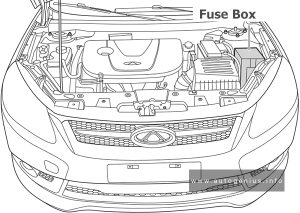
Fuse Box Location

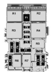
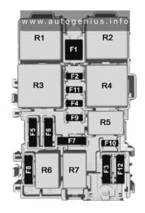
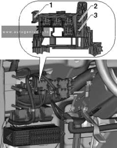
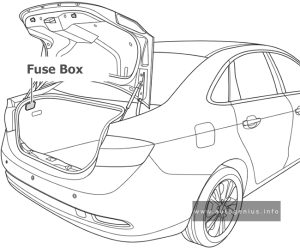
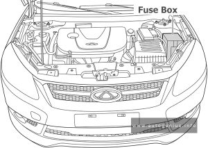
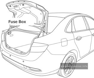
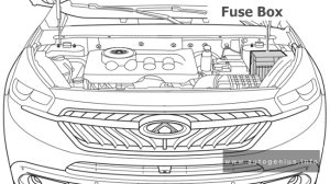
The fuse box is located on the left side of engine compartment and the rear side of left headlight.

Chery Tiggo 7 - fuse and relay box location - engine compartment
Chery Tiggo 7 – fuse and relay box location – engine compartment


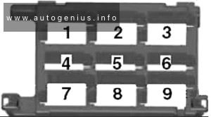
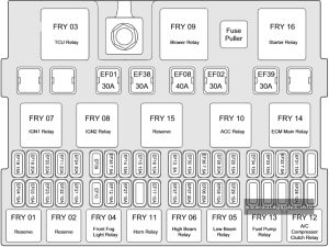
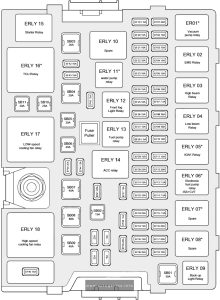
Fuse Box Diagram

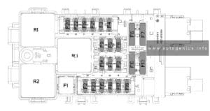
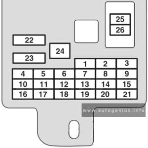
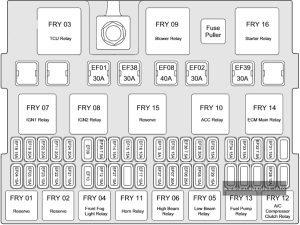
Chery Tiggo 7 - fuse and relay box diagram - engine compartment
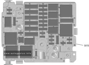
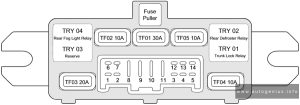
Chery Tiggo 7 – fuse and relay box diagram – engine compartment


Assignment of the fuses in the engine compartment

Description
SB01 Reserve
SB02 ACC
SB03 Starter/drive chain
SB04 TCU/DCT
SB05 BCM 2
SB06 BCM 1
SB07 ESP/ABS
SB08 EPB
SB09 ACM/EPB
SB10 ESP/ABS
SB11 Seat adjustment SEAT
EF01 Vacuum pump
EF02 Oxygen sensor
EF03 Ignition coil 3
EF04 ECU solenoid valve
EF05 PPD& HVH
EF06 Reserve
EF07 Right headlight high beam
EF08 Left headlight low beam
EF09 Reserve
EF10 ECU & fan controller with hybrid system
EF11 PEPS
EF12 LT & PTC water pump
EF13 ECU & TCU brake switch 15+ Sreversing sensor & IPU with hybridsystem
EF14 Inner mirror & A/C pressure switch& reversing radar
EF15 PEPS & 4WD
EF16 Electronic oil pump
EF17 Reserve
EF18 Back-up light
EF19 Alternator excitation
EF20 Injector
EF21 Reserve
EF22 Water pump
EF23 POD & PPD & EAC
EF24 Horn
EF25 Left headlight high beam
EF26 Right headlight low beam
EF27 Front fog light
EF28 ESP & ABS & ACM
EF29 Fuel pump
EF30 BCM 6
EF31 IGN 1
EF32 Brake switch & PEPS & DOT 30+
EF33 ACM
EF34 BCM 5
EF35 BCM 3
EF36 Reserve
EF37 Spare power 2
EF38 ECU & TCU 30+
EF39 Wiper
EF40 4WD & IPU
EF41 Seat heating
EF42 Air conditioning compressor
EF43 Reserve
EF44 BCM 4
EF45 Sunroof
EF46 Marine insurance
EF51


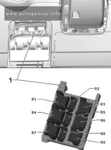
Power fuses

Fuse Box Diagram

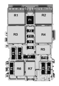
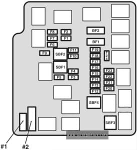
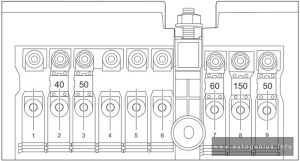
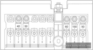
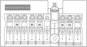
Chery Tiggo 7 - fuse and relay box diagram - engine compartment (power fuses)
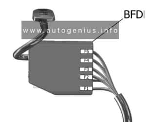
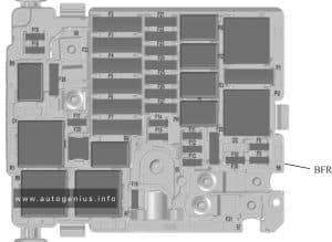
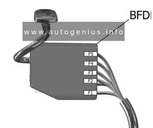
Chery Tiggo 7 – fuse and relay box diagram – engine compartment (power fuses)


Assignment of the power fuses

Amps Description
1
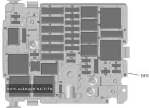
2 60A Instrument Panel Fuse and Relay Box
3
4 80A EPS
5 40A Low-speed Cooling Fan
6
7 150A Alternator
8 50A High-speed Cooling Fan
9

WARNING: Terminal and harness assignments for individual connectors will vary depending on vehicle equipment level, model, and market.

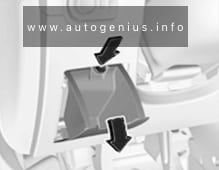
Chery Tiggo 8 (T18; 2017 – 2020) – fuse and relay box diagram

Chery Tiggo 8 (T18; 2017 – 2020) – fuse and relay box diagram

Year of production: 2017, 2018, 2019, 2020


The Chery Tiggo 8 PRO, a mid-size crossover, has been available since 2020 and continues to be produced. In this guide, you’ll find fuse box diagrams for the 2020, 2021, 2022, and 2023 models. It also provides information on the location of the fuse panels inside the vehicle, along with details about the fuse assignments (fuse layout) and relays.


Passenger Compartment Fuse Panel

Fuse Box Location

The fuses are located on the lower left side of instrument panel.

Chery Tiggo 8 PRO (2020 - 2023) - fuse and relay box location - passenger compartment
Chery Tiggo 8 PRO (2020 – 2023) – fuse and relay box location – passenger compartment


Fuse Box Diagrams

Chery Tiggo 8 PRO (2020 - 2023) - fuse and relay box diagram - passenger compartment (T1D)
Chery Tiggo 8 PRO (2020 – 2023) – fuse and relay box diagram – passenger compartment (T1D)


Assignment of the fuses in the instrument panel

Description
RF01 BCM & Instrument Cluster & Gateway
RF02
RF03 EPS & Angle Sensor
RF04 Multi-View Camera System
RF05 Airbag Module
RF06
RF07 A/C Control Panel & Radio Control Module & Head Lamps Adjust Sw Power & TBOX & Shift Lever (DCT)
RF08
RF09 A/C Control Panel & Radio Contrl Module & TBOX & DCDC
RF10 Instrument Cluster
RF11
RF12
RF13
RF14 Tachograph
RF15 Defrost Relay & EPB & Panoramic Image Module & OBD Diagnostic Interface & Sub-instrumentation Switch & Kick Wire Sensor
RF16
RF17
RF18 A/C Control Panel & Defrost Work Feedback
RF19
RF20 Rry01 Blower RLY
RF21
RF22
RF23
RF24 Rry03 Defrost RLY
RF25
RF26 BCM & Radio & Power Rear View Mirror Switch
RF27 Cigarette Lighter
RF28 Spare Power

Engine Compartment Fuse Box

Fuse Box Location

The fuse box is located on the left side of engine compartment and the rear side of left headlight.

Chery Tiggo 8 (T18; 2017 - 2020) - fuse and relay box location - engine compartment
Chery Tiggo 8 (T18; 2017 – 2020) – fuse and relay box location – engine compartment


Fuse Box Diagram

Chery Tiggo 8 (T18; 2017 - 2020) - fuse and relay box diagram - engine compartment
Chery Tiggo 8 (T18; 2017 – 2020) – fuse and relay box diagram – engine compartment


Assignment of the fuses in the engine compartment

Description
SB01 ISS 1
SB02 ACC
SB03 Start control
SB04 Rear Blower
SB05 BCM 2
SB06 BCM 1
SB07 ABS/EPS
SB08 ESP (EPB)
SB09 DCT
SB10 PLG
SB11 Seat adjustment
EF01 ERLY 01 vacuum pump RLY
EF02 Lambda sensor heating upstream & lambda sensor heating downstream
EF03 Ignition coil
EF04 ECU solenoid valve
EF05
EF06 AGS
EF07
EF08 Left Low beam power
EF09
EF10 ERLY 02 ECU RLY
EF11 PEPS
EF12
EF13 ECU & DCT & brake SW
EF14 AC & Sunroof & Reverse Radar Module
EF15 PEPS & DC-DC (ISS)
EF16 Rear Blower
EF17
EF18
EF19
EF20 Injector Cyl1.2.3.4
EF21 ISS 2
EF22
EF23
EF24 ERLY 20 High beam RLY
EF25
EF26 Right Low beam power
EF27 ERLY 12 horn RLY
EF28 ESP (EPB)
EF29 ERLY13 fuel pump RLY
EF30 BCM
EF31 IGN (a) & IGN (b)
EF32 PEPS & brake SW
EF33 PLG
EF34 BCM
EF35 BCM
EF36
EF37 Spare Power
EF38 ECU & DCT
EF39 Wiper RLY
EF40
EF41 Seat Heater
EF42 ERLY 19 AC clutch RLY
EF43
EF44 BCM
EF45 Sunroof
EF46 30IP (b) & DC-DC (ISS)
EF47 IP Fuse Box power
EF48 EPS power
EF49 ALT power
EF52 ERLY 17 Low Fan RLY
EF53 ERLY 18 High Fan RLY


WARNING: Terminal and harness assignments for individual connectors will vary depending on vehicle equipment level, model, and market.
Buick Enclave (2018 – 2021) – fuse and relay box diagram

Buick Enclave (2018 – 2021) – fuse and relay box diagram

Year of production: 2018, 2019, 2020, 2021


The Buick Enclave from model years 2018 to 2021 is part of the second generation of this midsize luxury SUV, which saw a significant redesign in 2018. 

Passenger compartment

Fuse Box Location

Buick Enclave - fuse and relay box location - passenger compartment
Buick Enclave – fuse and relay box location – passenger compartment


Fuse Box Diagram

Buick Enclave - fuse and relay box diagram - passenger compartment
Buick Enclave – fuse and relay box diagram – passenger compartment


Assignment of the fuses in the passenger compartment

Description
F1 Body control module 6
F2 Diagnostic link
F3 Electric steering column lock
F4 Rear USB port
F5 2021: Rear sunshade / Park/Reverse/Neutral/Drive/Low
F6 Heating, ventilation, and air conditioning
F7 Body control module 3
F8 2021: Adaptive front lighting system
F9 Right front heated seat
F10 Airbag
F11 2018-2020: Electronic precision shift
F12 Amplifier
F13 Body control module 7
F14 Left front heated seat
F15 Not Used
F16 Sunroof
F17 Communication gateway module
F18 2018-2020: Instrument cluster
2021: Instrument cluster / Head-up display
F19 Body control module 1
F20 Wireless charger module
F21 Body control module 4
F22 Infotainment
F23 Body control module 2
F24 2021: Park/Reverse/Neutral/Drive/Low
F25 2018-2020: Park assist
2021: Park assist/Shifter interface board
F26 Communications integration module
F27 Video
F28 Radio/Heating, ventilation, and air conditioning display
F29 Radio
F30 Steering wheel controls
F31 Front blower
F32 DC AC inverter
F33 Driver power seat
F34 Passenger power seat
F35 Feed/Body control module 4
F36 Electric power steering
F37 Power outlet/ Wireless charger/ Accessory
F38 Body control module 8
F39 Steering wheel controls backlighting
F40 Not Used (Circuit Breaker)
F41 Not Used (Circuit Breaker)
F42 Auxiliary power outlet / Lighter


Engine compartment

Fuse Box Location

Buick Enclave - fuse and relay box location - engine compartment
Buick Enclave – fuse and relay box location – engine compartment


Fuse Box Diagram

Buick Enclave - fuse and relay box diagram - engine compartment
Buick Enclave – fuse and relay box diagram – engine compartment


Assignment of the fuses in the engine compartment

Description
F1 Antilock brake system pump
F2 Starter 1
F3 DC DC transformer 1
F4 Not Used
F5 DC DC transformer 2
F6 Not Used
F7 Not Used
F8 Not Used
F9 Vacuum pump
F10 Front wiper
F11 Not Used
F12 Not Used
F13 Starter 2
F14 Not Used
F15 Rear wiper
F20 Not Used
F21 Not Used
F22 Electronic brake control module
F23 Parking/Trailer lamps
F24 Right trailer stoplamp/Turn signal lamp
F25 Steering column lock
F26 Not Used
F27 Left trailer stoplamp/Turn signal lamp
F28 Not Used
F29 Not Used
F30 Washer pump
F31 Not Used
F32 Left low-beam headlamp
F33 Front fog lamps
F34 Horn
F35 Not Used
F36 Not Used
F37 Right low-beam headlamp
F38 Automatic headlamp leveling motor
F39 Transmission control module
F40 Left rear bus electrical center/ Ignition
F41 Instrument cluster
F42 Heating, ventilation, and air conditioning
F43 2018-2020: Head-up display
2021: Head-up display/ Reflective light auxiliary display
F44 Communication gateway module/ Run/Crank
F45 Not Used
F46 Not Used
F47 Not Used
F48 Not Used
F49 Interior rearview mirror
F50 2018-2020: Fuel system control module
2021: Fuel system control module / Shifter interface board / Run/Crank
F51 Heated steering wheel
F52 Folding seats switch
F53 2021: Coolant pump
F54 2018-2020: Coolant pump
F55 Air conditioning clutch
F56 2018-2020: Integrated chassis control module
F57 Engine control module/lgnition
F58 Transmission control module/ Ignition
F59 Engine control module battery
F60 Engine control module-even
F61 O2 sensor 1/MAF
F62 Not Used
F63 O2 sensor 2/ Canister/Engine oil/ Turbo
F64 Aeroshutter
F65 Engine control module powertrain 1
F66 Engine control module powertrain 2
F67 Engine control module-odd
F68 Not Used
F69 Not Used
F70 Not Used
F71 Not Used
F72 Not Used
F73 Not Used
F74 Not Used
F75 Not Used
F76 Not Used
F77 Not Used
Relays
K1 Starter 1
K2 Run/Crank
K3 Vacuum pump
K4 Not Used
K5 Air conditioning
K6 2018-2020: Coolant pump
K7 Engine control module
K8 Folding seats
K9 Not Used
K10 Starter 2

Luggage compartment

Fuse Box Location

Buick Enclave - fuse and relay box location - luggage compartment
Buick Enclave – fuse and relay box location – luggage compartment


Fuse Box Diagram

Buick Enclave - fuse and relay box diagram - luggage compartment
Buick Enclave – fuse and relay box diagram – luggage compartment


Assignment of the fuses in the luggage compartment

Description
F1 Not Used
F2 Trailer
F3 Folding seats
F4 Rear blower
F5 Rear drive control
F6 Not Used
F7 Right window
F8 Rear defogger
F9 Left window
F10 Not Used
F11 Trailer reverse
F12 USB port/Third row seats
F13 Not Used
F14 Not Used
F15 Not Used
F16 Not Used
F17 Camera
F18 Not Used
F19 2018-2019: Ventilated seats
2020-2021: Ventilated seats / Massage
F24 Lumbar
F25 Not Used
F26 Trailer brake lamps
F27 2018-2019: Not Used
2020-2021: Massage
F28 Passive entry/ Passive start
F29 Not Used
F30 Canister vent
F31 Not Used
F32 Heated mirrors
F33 USB port/Second row seats
F34 Liftgate module
F35 2018-2020: Fuel system control module
2021: Fuel system control module / Fuel tank zone module.
F36 Not Used
F37 Not Used
F38 Window module
F39 Rear closure
F40 Memory seat module
F41 Automatic occupancy sensor
F42 Not Used
F43 Not Used
F44 Not Used
F45 Liftgate motor
F46 Rear heated seats
F47 Not Used
F48 Not Used
F49 Not Used
F50 Not Used
F51 Not Used
F52 Semi-active dampening system module
F53 Not Used
F54 External object calculating remote system/Side blind zone alert
F56 Universal remote system/Overhead console
F57 Hands free closure release
CB1 Not Used (Circuit Breaker)
CB2 Not Used (Circuit Breaker)
CB3 Rear auxiliary power outlet (Circuit Breaker)
Relays
K1 Not Used
K2 Not Used

WARNING: Terminal and harness assignments for individual connectors will vary depending on vehicle equipment level, model, and market.
Chevrolet Trax (2018 – 2022) – fuse and relay box diagram

Chevrolet Trax (2018 – 2022) – fuse and relay box diagram


Year of production: 2018, 2019, 2020, 2021, 2022


The Chevrolet Trax is a compact crossover SUV that Chevrolet produced from 2013, with the 2018-2022 models representing the latter part of its first generation.


Passenger Compartment Fuse Box

Fuse Box Location

The instrument panel fuse block is on the underside of the driver side instrument panel.

Chevrolet Trax - fuse and relay box location  - passenger compartment
Chevrolet Trax – fuse and relay box location – passenger compartment


Fuse Box Diagram

Chevrolet Trax - fuse and relay box diagram  - passenger compartment
Chevrolet Trax – fuse and relay box diagram – passenger compartment


Assignment of the fuses in the passenger compartment

Fuses Description
F1 Body control module 1
F2 Body control module 2
F3 Body control module 3
F4 Body control module 4
F5 Body control module 5
F6 Body control module 6
F7 Body control module 7
F8 Body control module 8
F9 Discrete logic ignition switch
F10 Sensing diagnostic module battery
F11 Data link connector
F12 HVAC module/ICS
F13 Liftgate relay
F14 Central gate module
F15 2018-2020: Lane departure warning/GENTEX
F16
F17 2018-2020: Electrical steering column lock
F18 Parking assist module/Side blind zone alert
F19 Body control module/Regulated voltage control
F20 Clock spring
F21 A/C/Accessory power outlet/ PRNDM
F22 Auxiliary power outlet/DC front
F23 2018-2020: HVAC/MDL/ICS
F24
F25 OnStar module/ Eraglonass
F26 2018: Heated steering wheel.
2019-2021: Electric vacuum pump
F27 2018-2020: Instrument cluster/ Auxiliary heater/ Auxiliary virtual image display
2021-2022: Instrument cluster
F28 2018-2020: Trailer feed 2
F29 2018-2020: Infotainment system
F30 2018-2020: DC DC 400W
F31 Instrument cluster module battery
F32 Silver box audio module/Navigation
F33 2018-2020: Trailer feed 1
F34 Passive entry/ Passive start
Midi Fuses
M01 2018-2020: Positive temperature coefficient
S/B Fuses
S/B01 2018: Passenger power seat 1
2019-2020: Powertrain cooling – 1
2021-2022: HVAC Aux heater – 1
S/B02 2018: Not Used.
2019-2020: Powertrain cooling – 2
2021-2022: HVAC Aux heater – 2
S/B03 Front power windows
S/B04 Rear power windows
S/B05 Logistic mode relay/ DC DC 400W
S/B06 Driver power seat
S/B07
S/B08 2018-2020: Trailer interface module
Circuit Breaker
CB1
Relays
RLY01 Accessory/Retained accessory power
RLY02 Liftgate
RLY03
RLY04 Blower
RLY05 Logistic mode

Engine Compartment Fuse Box

Fuse Box Location

Chevrolet Trax - fuse and relay box location  - engine compartment
Chevrolet Trax – fuse and relay box location – engine compartment


Fuse Box Diagram

Chevrolet Trax - fuse and relay box diagram  - engine compartment
Chevrolet Trax – fuse and relay box diagram – engine compartment


Assignment of the fuses in the engine compartment

Description
Mini Fuses
1 Sunroof
2 2018-2020: Exterior rearview mirror switch/ Driver side power window/ Rain sensor/ Universal garage door opener
2021-2022: Exterior rearview mirror switch/ Driver side power window/ Rain sensor
3 Canister vent solenoid
4
5 Electronic brake control module valve
6 2018-2020: Intelligent battery sensor
7 208-2021: Electric steering column lock
8 Transmission control module/FICM
9 Automatic occupancy sensing module
10 2018-2020: Headlamp leveling switch/ Headlamp leveling motor/ Rear vision camera/ Interior rearview mirror
2021: Rear vision camera/ Interior rearview mirror
2022: Rear vision camera
11 Rear wiper
12 Rear window defogger
13 Power lumbar switch
14 Exterior rearview mirror heater
15 Fuel system control module batterv
16 Heated seat module/ Memory module
17 2018-2020: TIM DC DC converter/Fuel system control module RC/ Compass module
2021: Fuel system control module RC/ Blow byheater
2022: Fuel system control module RC
18 Engine control module RC/ Transmission control module RC/ FICM RC
19 2018-2020: Fuel pump
20
21 Fan relay (auxiliary BEC)
22
23 Ignition coil/ Injector coil
24 Washer pump
25 2018-2020: Automatic headlamp leveling
26 EMS Var 1
27
28 2021-2022: Ignition 3
29 Engine control module powertrain/ Ignition 1/lgnition 2
30 EMS Var 2
31 Left high-beam headlamp
32 Right high-beam headlamp
33 Engine control module battery
34 Horn
35 A/C clutch
36 2018-2020: Front fog lamps
J-Case Fuses
1 Electronic brake control module pump
2 Front wiper
3 Linear power module blower
4 IEC RC
5
6
7
8 Cooling fan low – mid
9 Cooling fan – high
10 2018-2021: EVP
11 Starter solenoid
U-Micro Relays
2 2018-2021: Fuel pump
4
HC-Micro Relays
7 Starter
Mini Relays
1 Run/Crank
3 Cooling fan – mid
4
5 Powertrain relay
8 Cooling fan – low
HC-Mini Relays
6 Cooling fan – high


Auxiliary relay box

Relay Box Location
Chevrolet Trax - fuse and relay box location  - engine compartment (auxiliary relay box)
Chevrolet Trax – fuse and relay box location – engine compartment (auxiliary relay box)


Relay Box Diagram

Chevrolet Trax - fuse and relay box diagram  - engine compartment (auxiliary relay box)
Chevrolet Trax – fuse and relay box diagram – engine compartment (auxiliary relay box)


Assignment of the fuses in the auxiliary relay box

Relays Usage
01 2018-2020: Electric vacuum pump
02 Cooling fan control 1
03 Cooling fan control 2
04 2018-2020: Trailer (1.4L only)

Rear Compartment Fuse Box

Fuse Box Location

The rear compartment fuse box is located in the passenger side.

Chevrolet Trax - fuse and relay box location  - rear compartment
Chevrolet Trax – fuse and relay box location – rear compartment


Fuse Box Diagram

Chevrolet Trax - fuse and relay box diagram  - rear compartment
Chevrolet Trax – fuse and relay box diagram – rear compartment


Assignment of the fuses in the rear compartment 

Fuses Description
F1 2018-2020: Amplifier audio
F2 Rear drive control module
F3
F4
F5
F6
F7
F8
F9
F10
F11
F12
F13
F14
F15 _
F16
F17
S/B Fuses
S/B1 2018-2020: DC-DC transformer 400W
S/B2 2018-2020: DC-DC transformer 400W
S/B3 DC/AC inverter module
S/B4
S/B5
Relays
RLY01
RLY02
RLY03
RLY04
RLY05
Circuit Breakers
CB1


WARNING: Terminal and harness assignments for individual connectors will vary depending on vehicle equipment level, model, and market.
Honda Accord Hybrid (2018 – 2019) – fuse and relay box diagram

Honda Accord Hybrid (2018 – 2019) – fuse and relay box diagram

Year of production: 2018, 2019


The Honda Accord Hybrid (2018-2019) is a midsize sedan that blends the Accord’s well-known comfort, practicality, and refinement with hybrid efficiency. This generation introduced an advanced hybrid system aimed at providing impressive fuel economy without sacrificing performance. The Accord Hybrid was a part of the 10th-generation Accord lineup, which featured a more sophisticated design, modern technology, and a spacious, high-quality interior.


Passenger compartment fuse box

Fuse box location

Located under the dashboard.

Honda Accord Hybrid - fuse and relay location - passenger compartment
Honda Accord Hybrid – fuse and relay location – passenger compartment


Fuse box diagram


Assignment of the fuses in the Passenger compartment (2018, 2019)

Circuit Protected Amp
1
2 Driver’s Side Door Unlock 10 A
3 Passenger’s Side Door Unlock 10 A
4 ACCESSORY 10 A
5 ACC Key Lock 7.5 A
6 SRS 10 A
7
8 IG Hold2 (10 A)
9 SMART 10 A
10
11 Driver’s Side Door Lock 10 A
12 Driver’s Door Lock (10 A)
13 Passenger’s Side Door Lock 10 A
14 IG2_Option 10 A
15 Daytime Running Lights 10 A
16 Accessory Power Socket (Console Compartment) (20 A)
17 Moonroof (20 A)
18
19
20 Shift By Wire ECU (10 A)
21 Driver’s Door Unlock (10 A)
22
23
24 Premium Audio (20 A)
25
26
27
28
29
30
31
32 IG Hold3 (15 A)
33 Driver’s Power Seat Sliding (20 A)
34 Passenger’s Power Seat Sliding (20 A)
35 IG1_Option2 10 A
36 Meter 10 A
37 IG 1 _Option 1 10 A
38 Driver’s Power Seat Reclining (20 A)
39 Passenger’s Power Seat Reclining (20 A)
40 Driver’s Lumbar Support (10 A)
41
42 Front Air Ventilated Seat (20 A)
43 +B_Option 10 A
44 ADS (20 A)
45
46 SRS 10 A
47
48 Head-Up Display (10 A)
49 Door Lock 20 A
50 Front Accessory Power Socket 20 A
51 Rear Passenger’s Side Power Window 20 A
52 Rear Driver’s Side Power Window 20 A
53 Front Passenger’s Power Window 20 A
54 Driver’s Power Window 20 A

Engine Compartment Fuse Box

Fuse box location

Located near the battery.

Honda Accord Hybrid - fuse and relay location - engine compartment
Honda Accord Hybrid – fuse and relay location – engine compartment


Fuse box diagram


Assignment of the fuses in the Engine compartment (2018, 2019)

Circuit Protected Amp
1 Battery 150 A
2 (70 A)
2 EPS 70 A
2 (30 A)
2 Fuse Box Main 2 60 A
2 Electric Servo Brake 40 A
2 ABS/VSA FSR 40 A
2 SBW 1 30 A
2 IG Main 1 30 A
3 Rear Defogger 40 A
3 Fuse Box Main 1 60 A
3 (30 A)
3 Heater Motor 40 A
3 (40 A)
3 (30 A)
3 (30 A)
3 (30 A)
4 (30 A)
4 Fuse Box Option 2 (70 A)
4 (40 A)
4 Fuse Box Option 1 60 A
5 RFC 40 A
5 (30 A)
5 SRM2 30 A
5 ABS/VSA Motor 40 A
5 IG Main 2 30 A
5 ENG EWP 30 A
6 SRM1 30 A
7
8 Wiper Motor 30 A
9 Brake Light 10 A
10 EVTC 20 A
11 PCU EWP 15 A
12 RFC Coil 10 A
13 IGP 15 A
14 IG Hold 10 A
15 FI ECU 10 A
16 Battery Sensor 7.5 A
17 DBW 15 A
18 Ignition Coil 15 A
19 Hazard 15 A
20
21 P-ACT ECU 7.5 A
22 Heated Steering Wheel (10 A)
23
24 Audio 15 A
25 Rear Seat Heaters (20 A)
26 Heated Windshield (15 A)
27 Back Up 10 A
28 Horn 10 A
29 Front Fog Lights (10 A)
30 A/C EWP (10 A)
31
32 Washer Motor 15 A
33
34 (10 A)
35 Audio Sub (7.5 A)
36 IGPS (LAF) 7.5 A
37 IG1 E-PARKING 7.5 A
38 IG1 IPU 10 A
39 IG1 TCU 10 A
40 IG1 Fuel Pump 20 A
41 IG1 ABS/VSA 7.5 A
42 IG1 ACG 10 A
43 IG1 RFC 7.5 A
44 IG1 Monitor 7.5 A

WARNING: Terminal and harness assignments for individual connectors will vary depending on vehicle equipment level, model, and market.
Ram 5500 Chassis Cab (2018 – 2024) – fuse and relay box diagram

Ram 5500 Chassis Cab (2018 – 2024) – fuse and relay box diagram

Year of production: 2018. 2019, 2020, 2021, 2022, 2023, 2024


The Ram 5500 Chassis Cab (2018-2024) is the largest and most capable model in the Ram Chassis Cab lineup, designed specifically for heavy-duty commercial applications. Built to handle the most demanding tasks, such as heavy towing, hauling, and various custom upfits, the Ram 5500 offers exceptional power, durability, and flexibility for industries like construction, towing, and utility services.


Engine  Compartment

Fuse Box Location

The Power Distribution Center is located in the engine compartment near the battery. This center contains cartridge fuses, micro fuses, relays, and circuit breakers. A description of each fuse and component may be stamped on the inside cover, otherwise the cavity number of each fuse is stamped on the inside cover.

Ram 5500 Chassis Cab (2018 - 2024) - fuse and relay box location - engine compartment
Ram 5500 Chassis Cab (2018 – 2024) – fuse and relay box location – engine compartment


Fuse box diagram (Power Distribution Center)

Ram 5500 Chassis Cab (2018 - 2024) - fuse and relay box diagram - engine compartment
Ram 5500 Chassis Cab (2018 – 2024) – fuse and relay box diagram – engine compartment


Assignment of the fuses in the engine compartment

Cartridge Fuse Micro Fuse Description
F01 80A Black 2018-2018: Rad Fan Control Module – If Equipped (DS 1500 Only)
2019-2024: Spare
F02 60A Yellow 2018-2021: ABS Pump Motor (HD Only)
2022-2024: ABS Pump Mtr
F03 60A Yellow Rad Fan HI/Lo (if Equipped)
F04 50A Red 2019-2024: 400W Inverter
F05 40A Green / 50A Red Air Suspension Comp
F06 40A Green 2018: Antilock Brakes / Electronic Stability Control Pump
2019: ABS Pump Motor (DS 1500 Only)
2020-2024: Steering Torque Overlay Module (STOM)
F07 40A Green Starter Solenoid
F08 20A Blue 2018: Emissions Diesel – If Equipped
2019: NOX Sensor – If Equipped; Aux Relay Output – SSV Only
2020-2024: NOX Sensor (if Equipped)
F09 30A Pink / 40A Green 2018: Diesel Fuel Heater – If Equipped
2019: Aux Relay Output / Diesel Fuel Heater – If Equipped
2020-2024: Gas – Brake Vacuum Pump (if Equipped) / Diesel – Fuel Heater (if Equipped)
F10 40A Green / 50A Red Body Controller / Exterior Lighting #2
F11 30A Pink / 40A Green 2018: Integrated Trailer Brake Module – If Equipped
2019-2024: Brake System Module (ECU and Valves)
F12 40A Green Body Controller #3 / Power Locks
F13 40A Green HVAC Blower Motor
F14 40A Green Body Controller #4 / Exterior Lighting
F15 30A Pink 2019-2024: Power Side Step (if Equipped)
F16 30A Pink Smart-Bar Module (if Equipped)
F17 30A Pink 2019-2024: Winch Control Module – If Equipped
F18 Spare
F19 20A Blue / 30A Pink Diesel SCR Feed (if Equipped)
F20 30A Pink Passenger Door Mod
F21 30A Pink Drive Train Control Module
F22 20A Blue / 25A White / 30A Pink 2018: Engine Control Module
2019: Engine Control Module GPEC / Heavy Duty / Other – If Equipped
2020-2024: Gas – ECM (if Equipped) / Diesel – PCM (if Equipped)
F23 30A Pink Body Controller #1 / Interior Lighting
F24 30A Pink Driver Door Mod
F25 30A Pink Front Wiper
F26 30A Pink 2018-2019: Antilock Brakes / Stability Control Module / Valves – If Equipped
2020-2024: Spare
F27 Spare
F28 20A Blue Trailer Tow Backup Lights – If Equipped
F29 20A Blue Trailer Tow Parking Lights – If Equipped
F30 30A Pink 2018: Trailer Tow Receptacle
2019-2021: Trailer Tow Receptacle / Trailer Tow (Separate E-Brake) / Trailer Tow (BUX)
2022-2024: Trailer Tow
F31 30A Pink 2018: Urea Heater Control – If Equipped
2019: Diesel Heater Control – If Equipped (DS 1500 LD Diesel)
2020-2024: Spare
F32 Spare
F33 20A Blue 2018: Special Services Vehicle Only
2019-2024: Transmission Control Module (if Equipped)
F34 30A Pink Vehicle System Interface Module #2 (if Equipped)
F35 30A Pink Sunroof (if Equipped)
F36 30A Pink Rear Defroster (EBL) (if Equipped)
F37 30A Pink 2018: Cummins Diesel Fuel Heater #2 (If Equipped)
2019: Fuel Heater #2, Aux Relay 2 – If Equipped (HD Only); SSV (DS 1500 Only)
2020-2024: Diesel Frame / Fuel Heater (if Equipped)
F38 30A Pink 2018: Power Inverter 115V AC (If Equipped)
2019: Integrated Trailer Brake Module – If Equipped (HD Only); Power Inverter 115V AC – If Equipped (DS 1500 Only)
2020-2024: Integrated Trailer Brake Module (if Equipped)
F39 20A Blue 2018-2019: Power Outlet – Special Services Only
2020-2024: Spare
F40 10A Red 2019-2024: Ventilated Seats (if Equipped)
F41 10A Red 2018: Active Grille Shutter (If Equipped)
2019-2024: Active Grille Shutter / Active Air Dam (if Equipped)
F42 20A Yellow Horn
F43 15A Blue 2019-2024: Heated Steering Wheel (if Equipped)
F44 10A Red Diagnostic Port
F45 Spare
F46 10A Red Upfitters Relay Coils (if Equipped)
F47 Spare
F48 Spare
F49 10A Red / 15A Blue 2018: Instrument Panel Cluster (Except Fleet Vehicles)
2019: Instrument Panel Cluster / HVAC (DS 1500 Only); Instrument Cluster / MOD CSG (HD Only)
2020-2024: IP Cluster / CSG
F50 20A Yellow Air Suspension Control Module (if Equipped)
F51 10A Red 2018-2021: Ignition Node Module / Keyless Ignition Node Module, Radio Frequency Hub Module / Electric Steering Column Lock
2022-2024: Ignition Node Module / Keyless Ignition Node Module, Radio Frequency Hub Module
F52 5A Tan Battery Sensor
F53 20A Yellow Trailer Tow – Left Turn/Stop Lights
F54 20A Yellow Non Memory Adjustable Pedals (if Equipped)
F55 10A Red 2023-2024: Fwd Utility Lamps
F56 10A Red / 15A Blue 2018-2019: Additional Diesel Content (If Equipped)
2020-2024: Fuel Vapor Blocking Valve (VBV)
F57 20A Yellow TCM / PCM / Solenoid Trans Pressure SW
F58 10A Red 2019-2024: Bed Lighting (LED)
F59 Spare
F60 15A Blue 2018: Underhood Lamp
2019: Underhood Lamp / TCM – If Equipped (DS 1500 Only)
2020-2024: Spare
F61 10A Red 2018: PM Sensor (If Equipped)
2019: UREA Sensor / PM Sensor – If Equipped (DS 1500 LD Diesel & Cummins Diesel)
2020-2024: NH3 Sensor / PM Sensor (if Equipped)
F62 10A Red Air Conditioning Clutch
F63 20A Yellow 2018: Ignition Coils (Gas), Urea Heater (Cummins Diesel)
2019: Ignition Coils (Gas), Ignition Coils Capacitors (Gas) / Short Runner Valve Actuator / Urea Heater Control Unit (DS 1500 LD Diesel) / RLY Coil Feed-SCR (DS 1500 LD Diesel)
2020-2024: Ignition Coils / CAPS
F64 25A Clear Fuel Injectors / PCM (if Equipped)
F65 10A Red 2018: Spare
2019-2021: MOD Inverter (Wake Up) / Power Port / USB IP / WCPM – If Equipped (HD Only)
2022: Spare
2023-2024: RVDMP / MOD BLE (if Equipped)
F66 10A Red 2018: Sunroof / Passenger Window Switches / Rain Sensor
2019: Sunroof / Light and Rain Sensor Module / Inside Rearview Mirror / Passenger Window SW / USB Port Rear / Feed for R/A RLY #2 Coil (If Equipped)
2020-2021: Sunroof / USB Rear (If Equipped)
2022-2024: Sunroof / USB Rear / Inside Rearview Mirror/ Passenger Window SW
F67 10A Red 2018: CD / DVD / Bluetooth Hands-free Module (If Equipped)
2019: CD / DVD / UCI Port – If Equipped (HD Only); Bluetooth Hands-Free Module / CD – If Equipped (DS 1500 Only)
2020: CDM / UCI Port / USB Front
2021: UCI Port / USB Front
2022: UCI Port / USB Front / Trailer Gateway Module (360 Camera) / Tachograph
2023-2024: UCI Port / Trailer Gateway Module (360 Camera) / Tachograph
F68 10A Red 2019-2024: AEB RACAM HTR (if Equipped)
F69 15A Blue SCR Mod 12 Volt (if Equipped)
F70 30A Green 2018: Fuel Pump Motor
2019-2021: Fuel Pump Motor / K09 RLY Coil Feed (If Equipped)
2022-2024: Fuel Pump Mtr / Fuel Htr RLY
F71 25A Clear 2018: Amplifier
2019-2024: Amplifier / Active Noise Cancelation
F72 10A Red 2018: PCM (If Equipped)
2019: PCM / DC/DC Converter Voltage – If Equipped (DS 1500 Only)
2020-2024: Spare
F73 20A Yellow Fuel Transfer Pump (if Equipped)
F74 20A Yellow / 10A Red 2018-2019: Brake Vacuum Pump Gas/Diesel (If Equipped)
2020-2024: Backup Alarm
F75 10A Red 2018: Coolant Temperature Valve Actuator
2019: ATMM / Coil-SCR Module RLY – If Equipped (HD Only); Coolant Temperature Valve – If Equipped (DS 1500 Only)
2020-2024: ATMM / Coil-SCR Module RLY (if Equipped)
F76 10A Red 2018: Antilock Brakes / Electronic Stability Control
2019: Electronic Stability Control (HD Only); Brake System Module / Stop Lamp Switch / Electric Park Brake / Clutch Pedal Switch (DS 1500 Only)
2020-2024: Electronic Stability Control (ESC) (if Equipped)
F77 10A Red 2018: Drivetrain Control Module / Front Axle Disconnect Module
2019: Drivetrain Control Module / Front Axle Disconnect Module / TCM (HD Only); Drivetrain Control Module / ELSD / Front Axle Disconnect Module / Transmission Control Relay / RDM / Power Take Off Unit – If Equipped (DS 1500 Only)
2020-2024: Drivetrain Control Module / Front Axle Disconnect Module / TCM / STOM
F78 10A Red / 15A Blue 2018: Engine Control Module / Electric Power Steering
2019: Engine Control Module / Powertrain Control Module / AEB RACM MOD / Feed To AUX PDC Relay Coils (HD Only)
2020-2021: Engine Control Module / Powertrain Control Module / AEB RACM MOD / Feed To AUX PDC Relay Coils / HRLS
2022-2024: ECM / PCM / IRCM / AUX Relay Feed / HRLS
F79 15A Blue 2018: Clearance Lights
2019-2024: ID / Clearance Lt
F80 10A Red 2018: Universal Garage Door Opener / Compass
2019: Universal Garage Door Opener/Compass/Anti-Intrusion Module (DS 1500 Only); ASSY Overhead Console / SW Assist / SW 911 – If Equipped (HD Only)
2020-2024: Overhead Console / Assist / 911
F81 20A Yellow Trailer Tow Right Turn/Stop Lights
F82 10A Red Steering Column Control Module / Cruise Control
F83 10A Red 2023-2024: TLR AST / TLR RVS CTL / TLR KNB
F84 15A Blue 2018: Switch Bank / Instrument Cluster
2019-2024: ASBM / HVAC / ICS / Rear Heated Seat Switches
F85 10A Red ORC (Airbag)
F86 10A Red ORC (Airbag)
F87 10A Red 2018: Air Suspension – If Equipped / Trailer Tow / Steering Column Control Module
2019: Air Suspension / ITBM / Steering Column Control Module / MOD Gateway CAN-C Trailer TPM (HD Only); Air Suspension / Trailer Tow / DC/DC Converter (Voltage Stabilizer) / Steering Column Control Module / Occupant Classification Sensor (DS 1500 Only)
2020-2021: Air Suspension / ITBM / Steering Column Control Module / MOD Gateway CAN-C Trailer TPM
2022-2024: Air Susp / ITBM / SCCM / TLR TPM
F88 15A Blue Instrument Panel Cluster
F89 Spare
F90 20A Yellow Power Outlet / Batt (Customer Selectable)
F91 20A Yellow Power Outlet / Acc (Customer Selectable)
F92 10A Red 2023-2024: Invertor MOD / USB-IP / WCPM (if Equipped)
F93 20A Yellow 2018-2019: Cigar Lighter
F94 10A Red 2018: Shifter / Transfer Case Module
2019: Shift-By-Wire / Transfer Case Switch (DS 1500 Only); Shift-By-Wire/Transfer Case Switch / Module TPM Trailer (HD Only) / Module Gateway Can-C Trailer TPM (HD Only)
2020-2022: Shift-By-Wire / Transfer Case Switch / Module TPM Trailer / Module Gateway Can-C Trailer TPM
2023-2024: SBW / TCASE SW / TRL TPM – GTWY
F95 10A Red 2018: Rear Camera / Park Assist
2019: Rearview Camera / Park Assist / CHMSL Camera / Blind Spot Sensor / Surround View Camera (HD Only) Rear Camera / Park Assist/ Blind Spot Sensor / Compass (DS 1500 Only)
2020-2024: Rearview Camera / Park Assist / CHMSL Camera / Blind Spot Sensor / Surround View Camera
F96 10A Red 2018: Rear Seat Heater Switch
2019: Rear Seat Heater Switch / Trunk Lamp With Flashlamp Charger / Truck Lamp – If Equipped (DS 1500 Only); Trailer Camera – If Equipped (HD Only)
2020-2024: Trailer Camera (if Equipped)
F97 20A Yellow / 25A Clear 2018-2019: Rear Heated Seats & Heated Steering Wheel (If Equipped)
2020-2024: Front Heated Seat Passenger (if Equipped)
F98 20A Yellow / 25A Clear 2018-2019: Front Heated Seats (If Equipped)
2020-2024: Front Heated Seat Driver (if Equipped)
F99 10A Red 2018: Climate Control
2019: HVAC / DASM (DS 1500 Only); HVAC/ In-Car Temperature Sensor / CSG MOD / Humidity Sensor (HD Only)
2020-2021: HVAC / In-Car Temperature Sensor / CSG MOD
2022-2024: HVAC / In-Car Temperature Sensor / CSG MOD / Module Gateway Trailer / Tachograph
F100 10A Red Upfitter Box Feed (if Equipped)
F101 20A Yellow 2018: Electrochromatic Mirror / Smart High Beams (If Equipped)
2019: SSV Only
2020-2024: Rear Heated Seat Right (if Equipped)
F102 20A Yellow 2019-2024: Rear Heated Seat Left / Run RLY #3 Coil (if Equipped)
F103 10A Red HeadLamp AFLS (if Equipped)
F104 20A Yellow 2018: Power Outlets (Instrument Panel / Center Console)
2019: Power Outlets (Instrument Panel / Center Console) / Trunk – If Equipped (DS 1500 Only); UCI Port / USB Rear (HD Only)
2020-2024: UCI Port / USB Rear

WARNING: Terminal and harness assignments for individual connectors will vary depending on vehicle equipment level, model, and market.
Ram 4500 (2018 – 2024) – fuse and relay box diagram

Ram 4500 (2018 – 2024) – fuse and relay box diagram

Year of production: 2018. 2019, 2020, 2021, 2022, 2023, 2024


The Ram 4500 Chassis Cab (2018-2024) is a heavy-duty truck designed for commercial use, offering a balance of power, durability, and versatility. Built for industries that require high towing, payload capacity, and customization options, the Ram 4500 is positioned between the lighter-duty Ram 3500 and the more robust Ram 5500. It’s commonly used for applications such as towing, construction, and utility services, where strength and adaptability are essential.


Engine  Compartment

Fuse Box Location

The Power Distribution Center is located in the engine compartment near the battery. This center contains cartridge fuses, micro fuses, relays, and circuit breakers. A description of each fuse and component may be stamped on the inside cover, otherwise the cavity number of each fuse is stamped on the inside cover.

Ram 4500 Chassis Cab (2018 - 2024) - fuse box location - engine compartment
Ram 4500 Chassis Cab (2018 – 2024) – fuse and relay box location – engine compartment


Fuse box diagram (Power Distribution Center)

Ram 4500 Chassis Cab (2018 - 2024) - fuse and relay box diagram - engine compartment
Ram 4500 Chassis Cab (2018 – 2024) – fuse and relay box diagram – engine compartment


Assignment of the fuses in the engine compartment

Cartridge Fuse Micro Fuse Description
F01 80A Black 2018-2018: Rad Fan Control Module – If Equipped (DS 1500 Only)
2019-2024: Spare
F02 60A Yellow 2018-2021: ABS Pump Motor (HD Only)
2022-2024: ABS Pump Mtr
F03 60A Yellow Rad Fan HI/Lo (if Equipped)
F04 50A Red 2019-2024: 400W Inverter
F05 40A Green / 50A Red Air Suspension Comp
F06 40A Green 2018: Antilock Brakes / Electronic Stability Control Pump
2019: ABS Pump Motor (DS 1500 Only)
2020-2024: Steering Torque Overlay Module (STOM)
F07 40A Green Starter Solenoid
F08 20A Blue 2018: Emissions Diesel – If Equipped
2019: NOX Sensor – If Equipped; Aux Relay Output – SSV Only
2020-2024: NOX Sensor (if Equipped)
F09 30A Pink / 40A Green 2018: Diesel Fuel Heater – If Equipped
2019: Aux Relay Output / Diesel Fuel Heater – If Equipped
2020-2024: Gas – Brake Vacuum Pump (if Equipped) / Diesel – Fuel Heater (if Equipped)
F10 40A Green / 50A Red Body Controller / Exterior Lighting #2
F11 30A Pink / 40A Green 2018: Integrated Trailer Brake Module – If Equipped
2019-2024: Brake System Module (ECU and Valves)
F12 40A Green Body Controller #3 / Power Locks
F13 40A Green HVAC Blower Motor
F14 40A Green Body Controller #4 / Exterior Lighting
F15 30A Pink 2019-2024: Power Side Step (if Equipped)
F16 30A Pink Smart-Bar Module (if Equipped)
F17 30A Pink 2019-2024: Winch Control Module – If Equipped
F18 Spare
F19 20A Blue / 30A Pink Diesel SCR Feed (if Equipped)
F20 30A Pink Passenger Door Mod
F21 30A Pink Drive Train Control Module
F22 20A Blue / 25A White / 30A Pink 2018: Engine Control Module
2019: Engine Control Module GPEC / Heavy Duty / Other – If Equipped
2020-2024: Gas – ECM (if Equipped) / Diesel – PCM (if Equipped)
F23 30A Pink Body Controller #1 / Interior Lighting
F24 30A Pink Driver Door Mod
F25 30A Pink Front Wiper
F26 30A Pink 2018-2019: Antilock Brakes / Stability Control Module / Valves – If Equipped
2020-2024: Spare
F27 Spare
F28 20A Blue Trailer Tow Backup Lights – If Equipped
F29 20A Blue Trailer Tow Parking Lights – If Equipped
F30 30A Pink 2018: Trailer Tow Receptacle
2019-2021: Trailer Tow Receptacle / Trailer Tow (Separate E-Brake) / Trailer Tow (BUX)
2022-2024: Trailer Tow
F31 30A Pink 2018: Urea Heater Control – If Equipped
2019: Diesel Heater Control – If Equipped (DS 1500 LD Diesel)
2020-2024: Spare
F32 Spare
F33 20A Blue 2018: Special Services Vehicle Only
2019-2024: Transmission Control Module (if Equipped)
F34 30A Pink Vehicle System Interface Module #2 (if Equipped)
F35 30A Pink Sunroof (if Equipped)
F36 30A Pink Rear Defroster (EBL) (if Equipped)
F37 30A Pink 2018: Cummins Diesel Fuel Heater #2 (If Equipped)
2019: Fuel Heater #2, Aux Relay 2 – If Equipped (HD Only); SSV (DS 1500 Only)
2020-2024: Diesel Frame / Fuel Heater (if Equipped)
F38 30A Pink 2018: Power Inverter 115V AC (If Equipped)
2019: Integrated Trailer Brake Module – If Equipped (HD Only); Power Inverter 115V AC – If Equipped (DS 1500 Only)
2020-2024: Integrated Trailer Brake Module (if Equipped)
F39 20A Blue 2018-2019: Power Outlet – Special Services Only
2020-2024: Spare
F40 10A Red 2019-2024: Ventilated Seats (if Equipped)
F41 10A Red 2018: Active Grille Shutter (If Equipped)
2019-2024: Active Grille Shutter / Active Air Dam (if Equipped)
F42 20A Yellow Horn
F43 15A Blue 2019-2024: Heated Steering Wheel (if Equipped)
F44 10A Red Diagnostic Port
F45 Spare
F46 10A Red Upfitters Relay Coils (if Equipped)
F47 Spare
F48 Spare
F49 10A Red / 15A Blue 2018: Instrument Panel Cluster (Except Fleet Vehicles)
2019: Instrument Panel Cluster / HVAC (DS 1500 Only); Instrument Cluster / MOD CSG (HD Only)
2020-2024: IP Cluster / CSG
F50 20A Yellow Air Suspension Control Module (if Equipped)
F51 10A Red 2018-2021: Ignition Node Module / Keyless Ignition Node Module, Radio Frequency Hub Module / Electric Steering Column Lock
2022-2024: Ignition Node Module / Keyless Ignition Node Module, Radio Frequency Hub Module
F52 5A Tan Battery Sensor
F53 20A Yellow Trailer Tow – Left Turn/Stop Lights
F54 20A Yellow Non Memory Adjustable Pedals (if Equipped)
F55 10A Red 2023-2024: Fwd Utility Lamps
F56 10A Red / 15A Blue 2018-2019: Additional Diesel Content (If Equipped)
2020-2024: Fuel Vapor Blocking Valve (VBV)
F57 20A Yellow TCM / PCM / Solenoid Trans Pressure SW
F58 10A Red 2019-2024: Bed Lighting (LED)
F59 Spare
F60 15A Blue 2018: Underhood Lamp
2019: Underhood Lamp / TCM – If Equipped (DS 1500 Only)
2020-2024: Spare
F61 10A Red 2018: PM Sensor (If Equipped)
2019: UREA Sensor / PM Sensor – If Equipped (DS 1500 LD Diesel & Cummins Diesel)
2020-2024: NH3 Sensor / PM Sensor (if Equipped)
F62 10A Red Air Conditioning Clutch
F63 20A Yellow 2018: Ignition Coils (Gas), Urea Heater (Cummins Diesel)
2019: Ignition Coils (Gas), Ignition Coils Capacitors (Gas) / Short Runner Valve Actuator / Urea Heater Control Unit (DS 1500 LD Diesel) / RLY Coil Feed-SCR (DS 1500 LD Diesel)
2020-2024: Ignition Coils / CAPS
F64 25A Clear Fuel Injectors / PCM (if Equipped)
F65 10A Red 2018: Spare
2019-2021: MOD Inverter (Wake Up) / Power Port / USB IP / WCPM – If Equipped (HD Only)
2022: Spare
2023-2024: RVDMP / MOD BLE (if Equipped)
F66 10A Red 2018: Sunroof / Passenger Window Switches / Rain Sensor
2019: Sunroof / Light and Rain Sensor Module / Inside Rearview Mirror / Passenger Window SW / USB Port Rear / Feed for R/A RLY #2 Coil (If Equipped)
2020-2021: Sunroof / USB Rear (If Equipped)
2022-2024: Sunroof / USB Rear / Inside Rearview Mirror/ Passenger Window SW
F67 10A Red 2018: CD / DVD / Bluetooth Hands-free Module (If Equipped)
2019: CD / DVD / UCI Port – If Equipped (HD Only); Bluetooth Hands-Free Module / CD – If Equipped (DS 1500 Only)
2020: CDM / UCI Port / USB Front
2021: UCI Port / USB Front
2022: UCI Port / USB Front / Trailer Gateway Module (360 Camera) / Tachograph
2023-2024: UCI Port / Trailer Gateway Module (360 Camera) / Tachograph
F68 10A Red 2019-2024: AEB RACAM HTR (if Equipped)
F69 15A Blue SCR Mod 12 Volt (if Equipped)
F70 30A Green 2018: Fuel Pump Motor
2019-2021: Fuel Pump Motor / K09 RLY Coil Feed (If Equipped)
2022-2024: Fuel Pump Mtr / Fuel Htr RLY
F71 25A Clear 2018: Amplifier
2019-2024: Amplifier / Active Noise Cancelation
F72 10A Red 2018: PCM (If Equipped)
2019: PCM / DC/DC Converter Voltage – If Equipped (DS 1500 Only)
2020-2024: Spare
F73 20A Yellow Fuel Transfer Pump (if Equipped)
F74 20A Yellow / 10A Red 2018-2019: Brake Vacuum Pump Gas/Diesel (If Equipped)
2020-2024: Backup Alarm
F75 10A Red 2018: Coolant Temperature Valve Actuator
2019: ATMM / Coil-SCR Module RLY – If Equipped (HD Only); Coolant Temperature Valve – If Equipped (DS 1500 Only)
2020-2024: ATMM / Coil-SCR Module RLY (if Equipped)
F76 10A Red 2018: Antilock Brakes / Electronic Stability Control
2019: Electronic Stability Control (HD Only); Brake System Module / Stop Lamp Switch / Electric Park Brake / Clutch Pedal Switch (DS 1500 Only)
2020-2024: Electronic Stability Control (ESC) (if Equipped)
F77 10A Red 2018: Drivetrain Control Module / Front Axle Disconnect Module
2019: Drivetrain Control Module / Front Axle Disconnect Module / TCM (HD Only); Drivetrain Control Module / ELSD / Front Axle Disconnect Module / Transmission Control Relay / RDM / Power Take Off Unit – If Equipped (DS 1500 Only)
2020-2024: Drivetrain Control Module / Front Axle Disconnect Module / TCM / STOM
F78 10A Red / 15A Blue 2018: Engine Control Module / Electric Power Steering
2019: Engine Control Module / Powertrain Control Module / AEB RACM MOD / Feed To AUX PDC Relay Coils (HD Only)
2020-2021: Engine Control Module / Powertrain Control Module / AEB RACM MOD / Feed To AUX PDC Relay Coils / HRLS
2022-2024: ECM / PCM / IRCM / AUX Relay Feed / HRLS
F79 15A Blue 2018: Clearance Lights
2019-2024: ID / Clearance Lt
F80 10A Red 2018: Universal Garage Door Opener / Compass
2019: Universal Garage Door Opener/Compass/Anti-Intrusion Module (DS 1500 Only); ASSY Overhead Console / SW Assist / SW 911 – If Equipped (HD Only)
2020-2024: Overhead Console / Assist / 911
F81 20A Yellow Trailer Tow Right Turn/Stop Lights
F82 10A Red Steering Column Control Module / Cruise Control
F83 10A Red 2023-2024: TLR AST / TLR RVS CTL / TLR KNB
F84 15A Blue 2018: Switch Bank / Instrument Cluster
2019-2024: ASBM / HVAC / ICS / Rear Heated Seat Switches
F85 10A Red ORC (Airbag)
F86 10A Red ORC (Airbag)
F87 10A Red 2018: Air Suspension – If Equipped / Trailer Tow / Steering Column Control Module
2019: Air Suspension / ITBM / Steering Column Control Module / MOD Gateway CAN-C Trailer TPM (HD Only); Air Suspension / Trailer Tow / DC/DC Converter (Voltage Stabilizer) / Steering Column Control Module / Occupant Classification Sensor (DS 1500 Only)
2020-2021: Air Suspension / ITBM / Steering Column Control Module / MOD Gateway CAN-C Trailer TPM
2022-2024: Air Susp / ITBM / SCCM / TLR TPM
F88 15A Blue Instrument Panel Cluster
F89 Spare
F90 20A Yellow Power Outlet / Batt (Customer Selectable)
F91 20A Yellow Power Outlet / Acc (Customer Selectable)
F92 10A Red 2023-2024: Invertor MOD / USB-IP / WCPM (if Equipped)
F93 20A Yellow 2018-2019: Cigar Lighter
F94 10A Red 2018: Shifter / Transfer Case Module
2019: Shift-By-Wire / Transfer Case Switch (DS 1500 Only); Shift-By-Wire/Transfer Case Switch / Module TPM Trailer (HD Only) / Module Gateway Can-C Trailer TPM (HD Only)
2020-2022: Shift-By-Wire / Transfer Case Switch / Module TPM Trailer / Module Gateway Can-C Trailer TPM
2023-2024: SBW / TCASE SW / TRL TPM – GTWY
F95 10A Red 2018: Rear Camera / Park Assist
2019: Rearview Camera / Park Assist / CHMSL Camera / Blind Spot Sensor / Surround View Camera (HD Only) Rear Camera / Park Assist/ Blind Spot Sensor / Compass (DS 1500 Only)
2020-2024: Rearview Camera / Park Assist / CHMSL Camera / Blind Spot Sensor / Surround View Camera
F96 10A Red 2018: Rear Seat Heater Switch
2019: Rear Seat Heater Switch / Trunk Lamp With Flashlamp Charger / Truck Lamp – If Equipped (DS 1500 Only); Trailer Camera – If Equipped (HD Only)
2020-2024: Trailer Camera (if Equipped)
F97 20A Yellow / 25A Clear 2018-2019: Rear Heated Seats & Heated Steering Wheel (If Equipped)
2020-2024: Front Heated Seat Passenger (if Equipped)
F98 20A Yellow / 25A Clear 2018-2019: Front Heated Seats (If Equipped)
2020-2024: Front Heated Seat Driver (if Equipped)
F99 10A Red 2018: Climate Control
2019: HVAC / DASM (DS 1500 Only); HVAC/ In-Car Temperature Sensor / CSG MOD / Humidity Sensor (HD Only)
2020-2021: HVAC / In-Car Temperature Sensor / CSG MOD
2022-2024: HVAC / In-Car Temperature Sensor / CSG MOD / Module Gateway Trailer / Tachograph
F100 10A Red Upfitter Box Feed (if Equipped)
F101 20A Yellow 2018: Electrochromatic Mirror / Smart High Beams (If Equipped)
2019: SSV Only
2020-2024: Rear Heated Seat Right (if Equipped)
F102 20A Yellow 2019-2024: Rear Heated Seat Left / Run RLY #3 Coil (if Equipped)
F103 10A Red HeadLamp AFLS (if Equipped)
F104 20A Yellow 2018: Power Outlets (Instrument Panel / Center Console)
2019: Power Outlets (Instrument Panel / Center Console) / Trunk – If Equipped (DS 1500 Only); UCI Port / USB Rear (HD Only)
2020-2024: UCI Port / USB Rear

WARNING: Terminal and harness assignments for individual connectors will vary depending on vehicle equipment level, model, and market.
Volkswagen Touareg (CR; 2018 – 2025) – fuse and relay box diagram

Volkswagen Touareg (CR; 2018 – 2025) – fuse and relay box diagram

Year of production: 2018, 2019, 2020, 2021, 2022, 2023, 2024, 2025


The third-generation Volkswagen Touareg, with CR designations, was manufactured from 2018 through 2025. During this period, the model underwent a facelift. In this guide, we will provide an overview of the fuses and relays for the Volkswagen Touareg 3G, including fuse box diagrams, their locations.


Passenger compartment

Fuse box location

LHD: The fuses are located in the left footwell under the footrest.

Volkswagen Touareg 3G (CR; 2018 - 2025) - fuse and relay box location - passenger compartment - footwell (LHD)
Volkswagen Touareg 3G (CR; 2018 – 2025) – fuse and relay box location – passenger compartment – footwell (LHD)


RHD: The fuses are located behind a cover.

Volkswagen Touareg 3G (CR; 2018 - 2025) - fuse and relay box location - passenger compartment - footwell (RHD)
Volkswagen Touareg 3G (CR; 2018 – 2025) – fuse and relay box location – passenger compartment – footwell (RHD)


Fuse box diagram

Left-hand drive
Volkswagen Touareg 3G (CR; 2018 - 2025) - fuse and relay box diagram - passenger compartment - footwell (LHD)
Volkswagen Touareg 3G (CR; 2018 – 2025) – fuse and relay box diagram – passenger compartment – footwell (LHD)


Right-hand drive
Volkswagen Touareg 3G (CR; 2018 - 2025) - fuse and relay box diagram - passenger compartment - footwell (RHD)
Volkswagen Touareg 3G (CR; 2018 – 2025) – fuse and relay box diagram – passenger compartment – footwell (RHD)


Assignment of the fuses in the passenger compartment (footwell)

Amps Function / component
SA1
SA2 10A Circulation pump, MAF sensor, crankcase heating, coolant circulation pump
SA3 Radiator shutter
SA4 10A Circulation pump
Control unit for NOx sender
Control unit for NOx sender 2
Particulate sensor
Fuel tank shut-off valve
Exhaust flap control unit
SA5 5A Brake light switch
SA6 7.5A/15A Left electrohydraulic engine mounting solenoid valve
Right electrohydraulic engine mounting solenoid valve
Inlet cam actuator 1 for cylinder 1~4
Coolant valve for cylinder head
Coolant pump
Map-controlled engine cooling system thermostat
Cam adjustment actuator 1~8
Exhaust gas recirculation cooler changeover valve
Exhaust gas recirculation cooling bypass valve 2
Pressure reduction valve
Exhaust gas recirculation cooling bypass valve
Automatic glow period control unit
Glow period control unit 2
Gearbox mounting valve 2
SA7 5A/15A Lambda probe 1 after catalytic converter
Lambda probe after particulate filter 2
Air mass measurement module
Air mass meter 2
SA8 7.5A/15A Left electrohydraulic engine mounting solenoid valve
Coolant valve for gearbox
Gearbox mounting valve 1
Secondary air pump relay
Control unit for fuel tank leak detection
Coolant circulation pump
Right electrohydraulic engine mounting solenoid valve
Exhaust cam actuator 1 for cylinder 3
Exhaust cam actuator 1 for cylinder 1
Exhaust cam actuator 1 for cylinder 4
Exhaust gas recirculation cooler changeover valve
Inlet cam actuator 1 for cylinder 2
Inlet cam actuator 1 for cylinder 3
Inlet cam actuator 1 for cylinder 4
Inlet cam actuator 1 for cylinder 5
Inlet cam actuator 1 for cylinder 6
Continued coolant circulation pump
Map-controlled engine cooling system thermostat
Fuel pressure regulating valve
Fuel metering valve
Metering pump 2
SA9 5A Engine component current supply relay (motor relay)
SA10 5A Oil level and oil temperature sender
SA11 7.5A Accelerator pedal module, Radiator shutter
SA12 7.5A/10A/15A Air filter bypass flap valve
Secondary air inlet valve
Left electrohydraulic engine mounting solenoid valve
Right electrohydraulic engine mounting solenoid valve
Piston cooling jet control valve
Valve for oil pressure control
Intake manifold flap valve
Turbocharger air recirculation valve
Camshaft control valve 1
Exhaust camshaft control valve 1
Activated charcoal filter solenoid valve 1
Exhaust camshaft control valve 2
Camshaft control valve 2
Charge pressure control solenoid valve
Inlet cam actuator 1 for cylinder 1~8
Exhaust cam actuator 1 for cylinder 1~8
SA13 5A Radiator fan
SA14 15A/25A Engine/motor control unit
Injector 2, cylinder 1~4
SA15 10A/15A Lambda probe 1 after catalytic converter
Lambda probe 1 before catalytic converter
Lambda probe after particulate filter
SA16 30A Fuel pump control unit
SB1 20A Ignition coil 1~6 with output stage
SB2 Motor relay
SB3
SB4
SB5 30A Electrohydraulic engine mounting control unit
SB6 25A Front left seat belt
SB7 20A/40A Fuse holder F
SB8 25A Front right seat belt
SB9 20A/30A Fresh air blower control unit
SB10 Driver assistance control
SB11 40A/15A Starter relay 2
Thermal management control unit
SB12 Allwheel drive
SC1 30A Onboard supply control unit, Front seat heating
SC2 20A Driver door control unit
SC3 20A Onboard supply control unit (Socket supply)
SC4 30A Sliding sunroof adjustment control unit
SC5 30A Onboard supply control unit, Additional lighting, left
SC6 20A Rear driver side door control unit
SC7 30A Wiper motor control unit
SC8 20A Rear passenger side door control unit
SC9 30A Onboard supply control unit, (Additional lighting, right)
SC10 10A/30A Onboard supply control unit, Headlight / windshield washer system
SC11 20A/30A Potentiometer for electric trailer brakes, Air-conditioning control unit
SC12 30A Auxiliary heater control unit
Clutch actuator
SD1 5A Interior mirror
Heated rear seats control unit
Diagnostic connection
SD2 10A Data bus diagnostic interface
Onboard supply control unit, Parking sensors
SD3 7.5A Engine sound generator control unit, Sound system (E-Hybrid),
SD4 5A Gearbox oil cooling valve
SD5 5A Starter relay 1
Starter relay 2
Power and control electronics for electric drive
SD6
SD7 15A Accelerator pedal module
SD8 5A Control unit for night vision system
Anti-roll bar control unit
Anti-roll bar control unit 2
SD9 10A Adaptive cruise control unit
Front left radar sensor control unit for object detection
Front right radar sensor control unit for object detection
SD10 Allwheel drive, differential lock
SD11 10A Front camera for driver assist systems
SD12 7.5A Front left seat backrest fan 1
Front left seat cushion fan 1
Front right seat backrest fan 1
Front right seat cushion fan 1
SD13 5A USB charging socket 1
SD14 15A Rear window wiper motor
SD15 20A Front right headlight
SD16 20A Front left headlight
SE1 5A Anti-theft alarm sensor
Alarm horn
SE2 5A Main relay
SE3 5A Garage door operating unit
SE4 7.5A Selector lever sensors control unit
SE5 15A Onboard supply control unit (Horn)
SE6 5A Electromechanical parking brake button
SE7 5A/10A Data bus diagnostic interface (Gateway control unit)
SE8 5A Front roof module
SE9 Emergency call module, trailer hitch
SE10 5A/10A Airbag control unit
SE11 5A ABS control unit, ESC
SE12 10A Rain and light sensor
Diagnostic connection
SE13 20A Onboard supply control unit (Air conditioning system)
SE14 20A Front passenger door control unit
SE15 20A Onboard supply control unit, Air-conditioning compressor
SE16 30A DC/AC converter with socket, 12V – 230V
Brake system pressure accumulator, Smart actuator (E-Hybrid)

Single fuses (LHD)

Volkswagen Touareg 3G (CR; 2018 - 2025) - fuse and relay box diagram - passenger compartment - footwell - single fuses (LHD)
Volkswagen Touareg 3G (CR; 2018 – 2025) – fuse and relay box diagram – passenger compartment – footwell – single fuses (LHD)


Single fuses (LHD)

No.
A
Function/component
A 15A Seat and steering column adjustment control unit with memory
B 15A Front passenger seat adjustment with memory control unit
C 40A ABS control unit
D 40A ABS control unit
E
F 50A Gearbox auxiliary hydraulic pump

Single fuses (RHD)

Volkswagen Touareg 3G (CR; 2018 - 2025) - fuse and relay box diagram - passenger compartment - footwell - single fuses (RHD)
Volkswagen Touareg 3G (CR; 2018 – 2025) – fuse and relay box diagram – passenger compartment – footwell – single fuses (RHD)


Single fuses (RHD)

Amps Function / component
A 15A Seat and steering column adjustment control unit with memory
B 40A ABS control unit
C 40A ABS control unit
D
E

Driver’s Side Instrument Panel Fuse Box

Fuse Box Location

The fuses are located behind a cover on the driver’s side (both LHD and RHD).

Volkswagen Touareg 3G (CR; 2018 - 2025) - fuse and relay box location - instrument panel
Volkswagen Touareg 3G (CR; 2018 – 2025) – fuse and relay box location – instrument panel


Fuse Box Diagram

Left-hand drive
Volkswagen Touareg 3G (CR; 2018 - 2025) - fuse and relay box diagram - instrument panel (LHD)
Volkswagen Touareg 3G (CR; 2018 – 2025) – fuse and relay box diagram – instrument panel (LHD)


Right-hand drive
Volkswagen Touareg 3G (CR; 2018 - 2025) - fuse and relay box diagram - instrument panel (RHD)
Volkswagen Touareg 3G (CR; 2018 – 2025) – fuse and relay box diagram – instrument panel (RHD)


Assignment of the fuses in the instrument panel

Amps Function / component
SF1
SF2 5A Left effect loudspeaker
SF3 5A/7.5A Operating unit for driving mode selection
Operating unit to regulate suspension height
Button for driver assist systems
Switch module 1 in centre console
SF4 5A Control unit for Head-up Display
SF5 7.5A USB hub
SF6 10A Heater and air conditioning controls
SF7 5A/10A Steering column lock control element
SF8 5A/10A Multimedia system operating unit
SF9 10A Control unit in dash panel insert
SF10 5A Multimedia system operating unit
SF11 5A Rotary light switch
SF12 1A Steering column electronics control unit
SF13
SF14 5A/20A Control unit 1 for information electronics
SF15 25A Control unit for electrically adjustable steering column
SF16 10A Steering column electronics control unit


Engine Compartment Fuse Box

Volkswagen Touareg 3G (CR; 2018 - 2025) - fuse and relay box location - engine compartment
Volkswagen Touareg 3G (CR; 2018 – 2025) – fuse and relay box location – engine compartment


Slot Amps Function / component
A 15A Engine/motor control unit
B


Luggage compartment

Fuse box location

Volkswagen Touareg 3G (CR; 2018 - 2025) - fuse and relay box location - luggage compartment
Volkswagen Touareg 3G (CR; 2018 – 2025) – fuse and relay box location – luggage compartment


Fuse box diagram

Volkswagen Touareg 3G (CR; 2018 - 2025) - fuse and relay box diagram - luggage compartment
Volkswagen Touareg 3G (CR; 2018 – 2025) – fuse and relay box diagram – luggage compartment


Assignment of the fuses in the luggage compartment

Amps Function / component
SG1 10A Refrigerant pressure and temperature sender 1
Refrigerant pressure and temperature sender 2
Refrigerant expansion valve 2
High-voltage heater (PTC)
Radiator blind control motor
SG2
SG3
SG4
SG5 15A Adaptive suspension control unit
SG6 15A Automatic gearbox control unit
SG7 20A Onboard supply control unit 2
SG8 25A Operating and display unit for rear air conditioning system
SG9
SG10 25A Trailer detector control unit
SG11 30A Rear lid control unit
SG12 20A Rear fresh air blower control unit
SH1 20A Onboard supply control unit 2
SH2
SH3 30A Control unit for reducing agent metering system
DC/AC converter with socket, 12V – 230V
SH4 10A Operating and display unit for rear air conditioning system
SH5 25A Trailer detector control unit
SH6 30A Trailer detector control unit
SH7 15A Trailer detector control unit
SH8
SH9 15A Trailer detector control unit
SH10
SH11
SH12 25A Control unit for reducing agent metering system
SJ1 15A Driver assist systems control unit
SJ2 5A Aerial amplifier for mobile telephone
SJ3
SJ4 5A Lane change assist control unit
Lane change assist control unit 2
SJ5
SJ6 5A Tyre Pressure Monitoring System control unit
SJ7 15A Driver assist systems control unit
SJ8 5A Remote control receiver for auxiliary heater
SJ9
SJ10 5A TV tuner
SJ11 5A Roof aerial
SJ12 5A Garage door operation control unit
SJ13 5A Reversing camera system control unit
SJ14 20A Onboard supply control unit 2
SJ15
SJ16 40A Digital sound package control unit
SK1 5A Roll stabiliser control unit
Roll stabiliser control unit 2
SK2 7.5A Maintenance connector for high-voltage system
SK3 10A High-voltage battery coolant pump relay
SK4 7.5A Power and control electronics for electric drive
SK5 5A Brake servo
SK6
SK7
SK8 5A Air conditioner compressor with magnetic coupling and regulating valve
SK9 10A Battery, 48 V
Voltage converter (48V/12V)
SK10 5A High-voltage battery 1
SK11 7.5A Charging unit 1 for high-voltage battery
SK12
SK13
SK14 20A Thermal management coolant pump relay
SK15
SK16


Single fuses

Volkswagen Touareg 3G (CR; 2018 - 2025) - fuse and relay box diagram - luggage compartment (single fuses)
Volkswagen Touareg 3G (CR; 2018 – 2025) – fuse and relay box diagram – luggage compartment (single fuses)


Single fuses (luggage compartment)

Amps Function / component
A 15A Front passenger seat adjustment with memory control unit (right-hand drive)
B
C 30A Heated rear window relay
D 40A Adaptive suspension compressor electronics
E
F

WARNING: Terminal and harness assignments for individual connectors will vary depending on vehicle equipment level, model, and market.
Volkswagen e-Golf (2014 – 2020) – fuse and relay box diagram

Volkswagen e-Golf (2014 – 2020) – fuse and relay box diagram


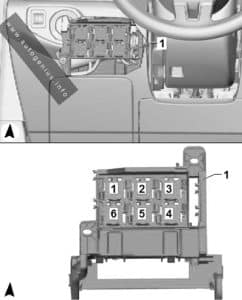
Year of production: 2014, 2015, 2016, 2017, 2018, 2019, 2020


This article provides the Volkswagen e-Golf, produced from 2014 to the 2020. It provides fuse box diagrams for the Volkswagen e-Golf models from 2014, 2015, 2016, 2017, 2018, 2019, 2029, 2021, and 2022, along with details on the location of the fuse panels within the vehicle. Additionally, it explains the fuse and relay assignments (fuse layout).


Passenger Compartment Fuse Box

Fuse Box Location

Volkswagen e-Golf (2014 - 2020) - fuse and relay box location - passenger compartment
Volkswagen e-Golf (2014 – 2020) – fuse and relay box location – passenger compartment


Fuse Box Diagram

Volkswagen e-Golf (2014 - 2020) - fuse and relay box diagram - passenger compartment
Volkswagen e-Golf (2014 – 2020) – fuse and relay box diagram – passenger compartment
Assignment of the fuses in the passenger compartment (instrument panel -SC-)
Amps Function / Component
SC1
SC2
SC3
SC4 10A 2014-2017:
Vehicle electrical system control module
– Anti-theft alarm system
SC4 7.5A/10A 2018-2020:
Alarm horn
SC5 5A/7.5A Data bus on board diagnostic interface
SC6 5A 2014-2015:
Anti-theft alarm system sensor2015-2020:
Selector lever
SC7 10A 2014-2015:
Heater and A/C controls
Climatronic control module
Selector lever
Rear window defogger relay2015-2020:
Heater and A/C controls
Climatronic control module
Rear window defogger relay
SC8 7.5A/10A 2014-2015:
Rotary light switch
Electromechanical parking brake button
Rain/light recognition sensor
Diagnostic connection2015-2020:
Rotary light switch
Electromechanical parking brake button
Rain/light recognition sensor
Anti-theft alarm system sensor
Diagnostic connection
SC9 5A/7.5A Steering column electronics control module
SC10 10A Front information display control head
SC11 25A 2014-2017:
Left front seat belt tensioner control module
SC11 40A 2017-2020:
Vehicle electrical system control module
– Left front headlamp
SC12 20A Information electronics control module 1
SC13 10A 2014-2017:
High-voltage battery 1
High-voltage system maintenance connector
SC13 25A 2017-2020:
Left front seat belt tensioner control module
SC14 30A Fresh air blower control module
SC15 10A Electronic steering column lock control module
SC16 7.5A Mobile communication 2-way signal amplifier
Telephone baseplate
Voltage converter for USB charge module (2014-2015)
USB distributor
Chip card reader control module
TV tuner
SC17 5A Instrument cluster
Control module for emergency call module and communication unit
Telematics Control Module for Real-Time Monitoring (2018-2020 vehicles with China equipment)
SC18 7.5A Rearview camera
Release button in rear lid handle
SC19 7.5A Access/start system interface
SC20 5A High-voltage battery charging voltage control module
SC21
SC22
SC23 40A 2014-2017:
Vehicle electrical system control module
– Right front headlamp
SC24 40A 2017-2020:
Vehicle electrical system control module
– Right front headlamp
SC25 30A Driver Door Control Module (LHD)
Left Rear Window Regulator Motor (LHD)
Front Passenger Door Control Module (RHD)
Right Rear Window Regulator Motor (RHD)
SC26 30A Vehicle electrical system control module
– Front heated seat
SC27 30A 2014-2017:
Digital sound system control module2017-2020:
Vehicle electrical system control module
– Terminal 30
SC28
SC29
SC30 10A 2017-2020:
High-voltage battery 1
High-voltage system maintenance connector
SC31 40A 2014-2017:
Vehicle electrical system control module
– Left front headlamp
SC32 7.5A/10A Driver assistance systems front camera
Distance regulation control module
Parking Aid Control Module
Parallel Parking Assistance Control Module
Blind spot detection control module
Blind spot detection control module 2
SC33 5A/7.5A Airbag control module
Front passenger airbag -disabled- indicator lamp
SC34 7.5A Rotary light switch
Interior rearview mirror
Sockets relay
Air quality sensor
Electromechanical parking brake button
SC35 7.5A/10A Diagnostic connection
Headlamp Range Control and Instrument Illumination Regulator Cornering lamp and headlamp range control module
SC36 5A 2014-2018:
Right LED headlamp power output module 1
SC36 10A 2018-2020:
Right front headlamp
– Right LED headlamp power output module 1
– Right Headlamp Power Output Module
– Left Light Control Module
SC37 5A 2014-2018:
Left LED headlamp power output module 1
SC37 10A 2018-2020:
Left front headlamp
– Left LED headlamp power output module 1
– Left Headlamp Power Output Module
– Right Light Control Module
SC38
SC39 30A Front Passenger Door Control Module (LHD)
Right Rear Window Regulator Motor (LHD)
Driver Door Control Module (RHD)
Left Rear Window Regulator Motor (RHD)
SC40 20A Cigarette Lighter
12V socket -U5-
12V socket 2 -U18-
From the factory, fuse SC40 is supplied by terminal 15 and can be supplied by terminal 30 instead, if equipment is connected to the socket or the cigarette lighter, make sure the equipment is disconnected from the power supply when the engine is off to prevent the battery from draining.
SC41 25A Right front seat belt tensioner control module
SC42 40A Vehicle electrical system control module
– Central locking system
SC43 30A 2014-2017:
Vehicle electrical system control module
– Terminal 302017-2020:
Digital sound system control module
SC44
SC45 15A Left Front Seat Adjustment Control Head
SC46
SC47 15A Rear window wiper motor
SC48 7.5A Engine sound generator control module
SC49 5A/7.5A High-voltage battery charging voltage control module
SC50
SC51
SC52
SC53 30A Rear window defogger relay
Relays
R1
R2
R3
R4 Power supply (terminal 15)
R5 Rear Window Defogger
R6 Sockets

Engine Compartment Fuse Box

Fuse Box Location

Volkswagen e-Golf (2014 - 2020) - fuse and relay box location - engine compartment
Volkswagen e-Golf (2014 – 2020) – fuse and relay box location – engine compartment

Fuse Box Diagram

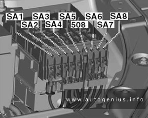
Volkswagen e-Golf (2014 - 2020) - fuse and relay box diagram - engine compartment
Volkswagen e-Golf (2014 – 2020) – fuse and relay box diagram – engine compartment


Assignment of the fuses in the engine compartment fuse box (-SA-, -SB-)

Amps Function / Component
SA1 125A Fuses (Instrument panel): 4, 5, 6, 7, 8, 9, 10, 11, 12, 13, 14, 31, 39, 41, 42, 53
Sockets relay
Power supply relay terminal 15
SA2 400A Electric drive power and control electronics
SA3 80A Power steering control module
SA4 80A Fuses (Instrument panel): 15, 16, 17, 18, 19, 20, 23, 24, 25, 26, 27, 43
SA5 50A Radiator fan
508 Battery Positive terminal
SB1 25A/40A ABS control module
SB2 40A ABS control module
– ABS hydraulic pump
SB3 15A Engine control module
SB4 5A Radiator fan
Radiator bypass switch-over valve
SB5
SB6
SB7 10A Radiator shutter motor
Water pump
Coolant pump in front of high-voltage heater (PTC)
SB8
SB9
SB10
SB11 40A Brake booster
SB12
SB13 7.5A 2018-2020:
Brake booster
SB14 40A Windshield defogger relay
SB15 15A Horn relay
SB16 10A High-voltage battery charger 1
Electric drive power and control electronics
SB17 7.5A Motronic engine control module power supply relay
Engine control module
ABS control module
Windshield defogger relay
Terminal 15 load reduction relay (2014-2016)
SB18 5A Battery monitoring control module
SB19 30A Wiper motor control module
SB20 10A Alarm horn
SB21
SB22
SB23
SB24
SB25
SB26
SB27
SB28
SB29
SB30
SB31
SB32
SB33 30A Brake system pressure reservoir
SB34 5A 2014-2018:
Brake booster
SB35 7.5A A/C relay
Thermal management control module
SB36
SB37
SB38
Relays
R1
R2
R3 Horn
R4 Brake Booster Vacuum Sensor link
R5 Main relay
R6 2014-2016:
Terminal 15 load reduction
R7
R8 A/C relay
R11 Windshield defogger

WARNING: Terminal and harness assignments for individual connectors will vary depending on vehicle equipment level, model, and market.
Holden Trax (TJ; 2017 – 2020) – fuse and relay box diagram

Holden Trax (TJ; 2017 – 2020) – fuse and relay box diagram


Year of production: 2017, 2018, 2019, 2020


This article provides the first-generation Holden Trax (TJ, facelifted) produced between 2017 and 2020. It provides fuse box diagrams for the 2017, 2018, 2019, and 2020 models, along with details on the location of the fuse panels within the vehicle and the specific functions of each fuse and relay (fuse layout).


Passenger Compartment Fuse Box

Fuse Box Location

The interior fuse block is located in the glove box.

Holden Trax (TJ; 2017 - 2020) - fuse and relay box location - passenger compartment
Holden Trax (TJ; 2017 – 2020) – fuse and relay box location – passenger compartment


Fuse Box Diagram

Holden Trax (TJ; 2017 - 2020) - fuse and relay box diagram - passenger compartment
Holden Trax (TJ; 2017 – 2020) – fuse and relay box diagram – passenger compartment


Assignment of the fuses in the passenger compartment

Description
F1 BCM 1
F2 BCM 2
F3 BCM 3
F4 BCM 4
F5 BCM 5
F6 BCM 6
F7 BCM 7
F8 BCM 8
F9 DLIS
F10 SDM B+
F11 DLC
F12 HVAC MDL
F13 L/GATE RLY
F14 CGM
F15 2018-2020: LDW Gentex
F16
F17 ESCL B+
F18 2017: UPA B+ / SBZA BT
2018-2020: PAS / SBZA
F19 BCM RVC
F20 Clock Spring
F21 2017: AC APO
2018-2020: APO AC / PRNDL
F22 2017: DC APO
2018-2020: APO DC FRT
F23
F24
F25 2018: OnStar
F26 2018: EVP
F27 2017: IPC
2018-2020: IPC PTC RLAD
F28 2018-2020: TRLR Feed2
F29
F30
F31 IPC B+
F32 Audio / Nav
F33 2018-2020: TRLR Feed1
F34 PEPS Module
S/B01 2018-2020: PTC 1
S/B02 2018-2020: PTC 2
S/B03 PWR WNDW MTR FRT
S/B04 PWR WNDW REAR
S/B05 Logistic Mode RLY
S/B06 2018-2020: PWR Seat DR
S/B07
S/B08 Trailer Interface Module
Relays
RLY1 ACC/RAP
RLY2 L/GATE
RLY3
RLY4 Blower
RLY5 Logistic Mode

Engine Compartment Fuse Box

Fuse Box Location

Holden Trax (TJ; 2017 - 2020) - fuse and relay box location - engine compartment
Holden Trax (TJ; 2017 – 2020) – fuse and relay box location – engine compartment


Fuse Box Diagram

Holden Trax (TJ; 2017 - 2020) - fuse and relay box diagram - engine compartment
Holden Trax (TJ; 2017 – 2020) – fuse and relay box diagram – engine compartment


Assignment of the fuses in the engine compartment

Description
F1 Sunroof
F2 OSRVM SW, Rain Sensor, PWR Window Driver
F3
F4
F5 EBCM Valve
F6
F7 ESCL
F8 TCM B+
F9
F10 HDLP Leveling SW, HDLP Leveling MTR LH/RH, Rear Vision Camera ISRVM
F11 Rear Wiper
F12 RR WDW Defog
F13
F14 OSRVM Heat
F15
F16 Heated Seat Module
F17 2017: Compass Module, TIM R/C
2018: Compass Module, TIM DC/DC Converter FSCM R/C
2019-2020: TIM
F18 ECM R/C, TCM R/C, FICM R/C
F19 Fuel Pump
F20
F21 Fan RLY (AUX BEC)
F22
F23 Ignition Coil, Injector Coil
F24 Washer Pump
F25
F26 2017: Canister Purge SOL, Water Valve SOL, Turbo Wastegate SOL, Turbo Bypass SOL, O2 Sensor Pre/Post
2018-2020: EMS Var-1
F27
F28
F29 ECM PT IGN-1, IGN-2
F30 2017: MAF Sensor
2018-2020: EMS Var-2
F31 High Beam LH
F32 High Beam RH
F33 ECM B+
F34 Horn
F35 A/C Clutch
F36 Front Fog Lamp
FU1 EBCM Pump
FU2 FRT Wiper
FU3 Blower
FU4 IEC R/C
FU5
FU6
FU7
FU8 Cooling Fan Low/Mid
FU9 Cooling Fan High
FU10 EVP
FU11 Starter SOL
SP Spare Fuses
Relays
1 Run Crank
2 Fuel Pump
3 2018-2020: Cooling Fan Mid
4
5 PT Relay
6 Cooling Fan High
7 Starter
8 Cooling Fan Low


Auxiliary relay box

Relay Box Location

The rear compartment fuse box is located in the passenger side of the rear compartment.
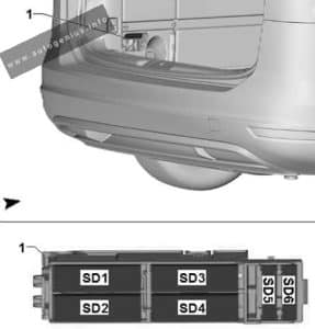
Holden Trax (TJ; 2017 - 2020) - fuse and relay box location - engine compartment (auxiliary relay box)
Holden Trax (TJ; 2017 – 2020) – fuse and relay box location – engine compartment (auxiliary relay box)


Relay Box Diagram

Holden Trax (TJ; 2017 - 2020) - fuse and relay box diagram - engine compartment (auxiliary relay box)
Holden Trax (TJ; 2017 – 2020) – fuse and relay box diagram – engine compartment (auxiliary relay box)


Assignment of the fuses in the auxiliary relay box

Relays
RLY01 ELECTRIC VACUUM PUMP
RLY02 COOLING FAN 1
RLY03 COOLING FAN 2
RLY04

Rear Compartment Fuse Box

Fuse Box Location

The rear compartment fuse box is located in the passenger side of the rear compartment.
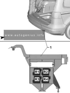
Holden Trax (TJ; 2017 - 2020) - fuse and relay box location - rear compartment
Holden Trax (TJ; 2017 – 2020) – fuse and relay box location – rear compartment


Fuse Box Diagram (2017)

Holden Trax (TJ; 2017) - fuse and relay box diagram - rear compartment
Holden Trax (TJ; 2017) – fuse and relay box diagram – rear compartment


Assignment of the fuses in the rear compartment (2017)

Description
F1
F2
F3
F4
F5
F6
F7
F8
F9
F10
F11
F12
F13
F14
F15
F16
F17 Spare
F18
S/B01
S/B02
S/B03
S/B04 AC DC INV
S/B05
S/B06
S/B07
S/B08
Relays
RLY1
RLY2


Fuse Box Diagram (2018 – 2020)

Holden Trax (TJ; 2018 - 2020) - fuse and relay box diagram - rear compartment
Holden Trax (TJ; 2018 – 2020) – fuse and relay box diagram – rear compartment


Assignment of the fuses in the rear compartment (2018 – 2020)

Description
F1 2018: Amplifier
F2 2018: RDCM
F3
F4 2018: NOX Soot
F5 2018: NOX Soot/Heater Pipe
F6 2018: SCRPM
F7 2018: SCRPM
F8
F9
F10
F11
F12
F13
F14
F15
F16
F17
SB1 2018: DC/DC
SB2 2018: DC/DC
SB3 DC/AC Inverter
SB4 2018: NOX Heater Pipe
SB5
Relays
RLY1
RLY2
RLY3 2018: ECM/NOX Soot
RLY4 2018: ECM/NOX Heater Pipe
RLY5

WARNING: Terminal and harness assignments for individual connectors will vary depending on vehicle equipment level, model, and market.