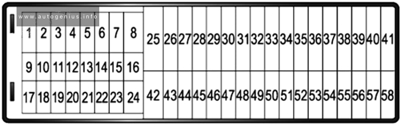
Seat Alhambra (MK2/7N; 2010 – 2020) – fuse and relay box diagram

Seat Alhambra (MK2/7N; 2010 – 2020) – fuse and relay box diagram

Year of production: 2010, 2011, 2012, 2013, 2014, 2015, 2016, 2017, 2018, 2019, 2020


This article covers the second-generation SEAT Alhambra (7N), produced from 2010 to 2020. It includes fuse box diagrams for the 2010–2020 models, provides details on the locations of the fuse panels within the vehicle, and explains the function of each fuse (fuse layout) and relay.


Passenger compartment fuse box

Fuse Box Location

To remove the cover, move the activation lever in the lower part to the right. For right-hand drive vehicles, move the lever to the left.

Seat Alhambra (MK2/7N; 2010 - 2020) - fuse and relay box location - passenger compartment
Seat Alhambra (MK2/7N; 2010 – 2020) – fuse and relay box location – passenger compartment


Fuse Box Diagram (-SC-)

Seat Alhambra (MK2/7N; 2010 - 2020) - fuse and relay box location - passenger compartment (holder C)
Seat Alhambra (MK2/7N; 2010 – 2020) – fuse and relay box location – passenger compartment (holder C)


Assignment of the fuses in the instrument panel (Fuse holder C)

Amps Function/component
1 not assigned
2 7.5A 2018-2020:
USB connection 1
3 7.5A 2016-2020:
Left washer jet heater element
Right washer jet heater element
4 10A DC/AC converter with socket, 12V – 230V
Voltage stabiliser
Starter relay 1 (with start-stop)
Starter relay 2 (with start-stop)
5 10A Electronically controlled damping control unit
6 10A 2015-2020:
Blind Spot Monitor control unit
Blind Spot Monitor control unit 2
7 not assigned
8 not assigned
9 7.5A Warning lamp for airbag deactivated on front passenger side
Airbag control unit
10 5A 2013-2020 (taxi):
Taximeter
Mirror taximeter
Voltage stabiliser
Taxi alarm remote control, control unit
11 10A All-wheel drive control unit
12 10A Left gas discharge (xenon) bulb
13 5A 2010-2015:
Electromechanical parking brake button
Oil level and oil temperature sender
Reversing light switch
Operating unit in front of centre console
High-pressure sender
Parking aid control unit
Interior mirror
Front camera for driver assist systems
13 5A 2015-2020:
Operating unit in front of centre console
Reversing light switch
High-pressure sender
Trailer detector control unit
Air quality sensor
Adaptive cruise control unit
Parking aid control unit
Park assist steering control unit
Front camera for driver assist systems
Automatic anti-dazzle interior mirror
14 7.5A 2010-2015:
Light switch
Trailer detector control unit
Control unit for electromechanical parking brake
ABS control unit
Brake light switch
Power steering control unit
Engine/motor control unit
Data bus diagnostic interface
Control unit in dash panel insert
14 7.5A 2015-2016:
Light switch
ABS control unit
Control unit in dash panel insert
Trailer detector control unit
Power steering control unit
Data bus diagnostic interface
Engine/motor control unit
14 7.5A 2016-2020:
Light switch
ABS control unit
Control unit in dash panel insert
Operating unit in front of centre console
Power steering control unit
Switch module 2 in centre console
Data bus diagnostic interface
Engine/motor control unit
Electromechanical parking brake button
Oil level and oil temperature sender
15 10A 2010-2015:
Auxiliary heater operation relay
Diagnostic connection
Front left headlight, not xenon
Front right headlight, not xenon
Control unit for cornering light and headlight range control
Switch and instrument illumination regulator
Ar mass meter
15 10A 2015-2020:
Switch and instrument illumination regulator
Control unit for cornering light and headlight range control
Front left headlight, not xenon
Front right headlight, not xenon
Diagnostic connection
16 10A Right gas discharge (xenon) bulb
17 5A 2010-2015:
Mobile telephone operating electronics control unit
Emergency call module control unit and communication unit
17 5A 2015-2020:
Emergency call module control unit and communication unit (LHD)
18 7.5A 2010-2015:
Taxi alarm remote control, control unit
Data transmission control unit
19 not assigned
20 5A ABS control unit
21 5A 2010-2016:
2nd heat exchanger switch-off valve
21 5A 2016-2020:
Electromechanical parking brake button
Selector lever
22 7.5A Light switch
Rain and light sensor
Reversing camera system control unit
Diagnostic connection
23 7.5A 2010-2015:
Selector lever sensors control unit
Electromechanical parking brake button
Climatronic control unit
Air conditioning system control unit
Operating and display unit for rear air conditioning system
Rear blower regulation sender
Remote control receiver for auxiliary coolant heater
23 7.5A 2015-2020:
Operating and display unit for rear air conditioning system
Rear blower regulation sender
Climatronic control unit
Remote control receiver for auxiliary coolant heater
2nd heat exchanger switch-off valve (2016-2020)
24 7.5A Entry and start authorisation control unit
25 7.5A Selector lever
Mechatronic unit for dual clutch gearbox
26 5A 2010-2016:
Air quality sensor
27 not assigned
28 15A Rear window wiper motor
29 30A 2010-2015:
12V socket
12V socket 3
Blocking diode
29 20A 2015-2020:
Blocking diode
Cigarette lighter
12V socket
12V socket 2
12V socket 3
Onboard supply control unit (T52c/21)
Terminal 75 diagnosis feedback
30 30A 2010-2015:
Cigarette lighter
12V socket 2
Onboard supply control unit (T52c/21)
Terminal 75 diagnosis feedback
30 20A 2015:
Cigarette lighter
12V socket 2
30 30A 2015-2020:
Blower relay
31 not assigned
32 not assigned
33 not assigned
34 not assigned
35 not assigned
36 30A 2010-2015:
Control unit for electromechanical parking brake
36 5A 2015-2016:
Two-way signal amplifier for mobile telephone/data services
Storage compartment with interface for mobile telephone
36 20A 2016-2020:
Control unit 1 for information electronics
36 30A 2020:
Right sliding door control unit
37 10A/25A 2010-2011:
Two-way radio
or
Sliding sunroof adjustment control unit
37 25A 2011-2020:
Sliding sunroof adjustment control unit
38 10A/30A 2010-2011:
Taximeter
Interior light switch
Taxi sign switch
Taxi alarm active button
Mirror taximeter
Front interior light button
or
Sunroof roller blind control unit
38 30A 2011-2020:
Sunroof roller blind control unit
39 5A/7.5A Steering column electronics control unit
40 5A 2010-2015:
Multimedia system control unit
40 5A 2016-2020:
Two-way signal amplifier for mobile telephone/data services
Storage compartment with interface for mobile telephone
41 5A Dash panel insert
42 15A Electronically controlled damping control unit
43 30A 2010-2017:
Driver seat lumbar support adjistment switch
Front passenger seat lumbar support adjistment switch
44 25A/30A Fresh air blower relay (LHD)
Heated rear window relay
45 30A Front passenger door control unit
Rear right door control unit
46 30A Driver door control unit
Rear left door control unit
47 10A 2011-2020 (taxi):
Interior light switch
Taxi sign switch
Taxi alarm active button
Mirror taximeter (2011-2015)
Front interior light button (2013-2015)
48 15A Alarm horn
Interior monitoring sensor
Onboard supply control unit (T52c/1)
Terminal 30, Anti-theft alarm supply
49 30A 2010-2015:
Control unit for electromechanical parking brake
49 7.5A 2015-2020:
Relay for reducing agent metering system (diesel)
Delivery unit for reducing agent metering system (diesel)
50 30A Onboard supply control unit (T52b/1)
Terminal 30, central locking supply
51 30A Heated front seats control unit
52 20A 2010-2011:
Headlight washer system relay
Headlight washer system pump
52 30A 2011-2020:
Rear fresh air blower
53 30A DC/AC converter with socket, 12V – 230V
54 5A/10A Control unit for electronic steering column lock
55 25A 2010-2013:
Trailer voltage supply control unit
55 20A 2013-2020:
All-wheel drive control unit
56 30A 2010-2013:
Trailer detector control unit
56 30A 2015-2020:
Control unit for reducing agent metering system (diesel)
57 10A 2011-2015:
Two-way radio
58 25A 2010-2015:
Special vehicle control unit
58 30A 2015-2020 (taxi):
Voltage stabiliser
58 20A 2020:
Control unit 1 for information electronics (RHD)

Individual fuses (SR1)
Seat Alhambra (MK2/7N; 2010 - 2020) - fuse and relay box location - passenger compartment (individual fuses (SR1))
Seat Alhambra (MK2/7N; 2010 – 2020) – fuse and relay box location – passenger compartment (individual fuses (SR1))


Assignment of the fuses in the instrument panel (Individual fuses (SR1))

Amps Function/component
1 40A Right sliding door control unit
2 20A/30A Driver seat adjustment operating unit
Driver seat adjustment control unit
Driver seat backrest adjustment switch
Driver seat lumbar support adjustment switch
3 20A/30A Front passenger seat adjustment operating unit
Front passenger seat backrest adjustment switch
Front passenger seat lumbar support adjustment switch


Relay carrier #1 (on left behind dash panel)

2010-2015

Seat Alhambra (MK2/7N; 2010 - 2020) - fuse and relay box location - passenger compartment (Relay carrier #1))
Seat Alhambra (MK2/7N; 2010 – 2020) – fuse and relay box location – passenger compartment (Relay carrier #1))


Assignment of the fuses in the instrument panel (Relay carrier #1)

Relay
1 Terminal 50 voltage supply relay (without start/stop)
2 Heated rear window relay
3 Auxiliary heater operation relay (with auxiliary heater, LHD)
Low heat output relay (with auxiliary heater)
4 not assigned
5 not assigned
6 Fresh air blower relay (with auxiliary heater)
7 2010-2012: Additional coolant pump relay (petrol)
8 2010-2012: Dual tone horn relay
9 2010-2012: Headlight washer system relay


2016-2020


Seat Alhambra (MK2/7N; 2010 - 2020) - fuse and relay box location - passenger compartment (Relay carrier #1))
Seat Alhambra (MK2/7N; 2010 – 2020) – fuse and relay box location – passenger compartment (Relay carrier #1))


Assignment of the fuses in the instrument panel (Relay carrier #1)

Relay
R1 not assigned
R2 not assigned
R3 not assigned
R4 not assigned
R5 Blower relay
R6 Heated rear window relay
R7 not assigned
R8 Fresh air blower relay (LHD)
R9 Low heat output relay
Auxiliary heater operation relay (LHD)
Relay carrier #2 (SR1, on left under dash panel)
Seat Alhambra (MK2/7N; 2010 - 2020) - fuse and relay box location - passenger compartment (Relay carrier #2))
Seat Alhambra (MK2/7N; 2010 – 2020) – fuse and relay box location – passenger compartment (Relay carrier #2))


Assignment of the fuses in the instrument panel (Relay carrier #2)

Relay
1 2010-2016: High heat output relay (LHD)
2016-2020: Terminal 15 voltage supply relay 2
2 Terminal 75 voltage supply relay 1
3 2010-2016: Terminal 15 voltage supply relay 2
2016-2020: High heat output relay (LHD)
4 Heated windscreen relay
5 High heat output relay (RHD)
6 not assigned


Engine compartment fuse box

Fuse Box Location

Move the attachment tabs forwards, in the direction indicated by the arrow to release the fuse box cover. Then lift the cover out.

Seat Alhambra (MK2/7N; 2010 - 2020) - fuse and relay box location - engine compartment
Seat Alhambra (MK2/7N; 2010 – 2020) – fuse and relay box location – engine compartment


Fuse Box Diagram (-SA-)

Seat Alhambra (MK2/7N; 2010 - 2020) - fuse and relay box diagram - passenger compartment (-SA)
Seat Alhambra (MK2/7N; 2010 – 2020) – fuse and relay box diagram – passenger compartment (-SA)


Assignment of the fuses in the engine compartment (holder A)

Amps Function/component
SA1 150A/200A/400A Alternator
SA2 80A Power steering control unit
SA3 80A Radiator fan control unit
SA4 80A Fuse holder D -SD-
SA5 100A Fuse holder C -SC- 20-pin jumper
508 Terminal 30 wiring junction
SA6 50A Heated windscreen relay
SA7 70A High heat output relay
SA8 60A Thermal fuse 2 – rear right sliding door
Driver seat adjustment thermal fuse 1
Front passenger seat adjustment thermal fuse 1


Fuse Box Diagram (-SB-)

Seat Alhambra (MK2/7N; 2010 - 2020) - fuse and relay box diagram - engine compartment (holder B)
Seat Alhambra (MK2/7N; 2010 – 2020) – fuse and relay box diagram – engine compartment (holder B)


Assignment of the fuses in the engine compartment (Fuse holder B)

Amps Function/component
F1 30A 2010-2016: Voltage stabiliser
F1 20A 2016-2020:
Control unit 1 for information electronics
Display unit for front information display and operating unit control unit
F2 30A Onboard supply control unit (T52b/42)
Terminal 30 power
F3 30A 2010-2016:
ABS control unit
Wiper motor control unit
F3 30A 2016-2017:
Wiper motor control unit
F3 20A/30A 2017-2020:
Headlight washer system relay
Headlight washer system pump
F4 30A Onboard supply control unit (T52a/1)
terminal 30, left light supply
F5 5A Onboard supply control unit (T52a/24)
terminal 30, reference
Battery monitor control unit
F6 30A Onboard supply control unit (T52c/42)
terminal 30, right light supply
F7 25A Dual tone horn relay
Heated windscreen relay
F8 30A Digital sound package amplifier
F9 20A 2010-2015:
Control unit with display for radio and navigation
F9 15A 2018-2020:
Additional coolant pump relay (petrol)
Vacuum pump for brakes (petrol)
Brake servo pressure sensor
F10 30A Engine/motor control unit
F11 5A Data bus diagnostic interface
F12 15A Mechatronic unit for dual clutch gearbox
F13 5A Engine/motor control unit
Main relay
Fuse 10 on fuse holder B
Fuse 14 on fuse holder B
Fuse 16 on fuse holder B
Fuse 18 on fuse holder B
Fuse 20 on fuse holder B
Fuse 23 on fuse holder B
Fuse 24 on fuse holder B
F14 30A/15A/10A 2010-2015:
Pump for reducing agent (diesel)
Ignition coil 1~4 with output stage
F14 15A/30A 2015-2020:
Ignition coil 1~4 with output stage
Coolant shut-off valve
Coolant valve for gearbox
F14 30A 2020:
Ignition coil 1~4 with output stage
F15 not assigned
F16 15A/30A 2010-2015:
Control unit for reducing-agent heater (diesel)
Lambda probe
Lambda probe after catalytic converter
Magnetic clutch for supercharger
F16 15A/30A 2015-2016:
Lambda probe 1 after catalytic converter (petrol)
Lambda probe 1 before catalytic converter (petrol)
Activated charcoal filter solenoid valve 1 (petrol)
Camshaft control valve 1 (2016)
F16 15A 2016-2020:
Lambda probe 1 after catalytic converter (petrol)
Lambda probe 1 before catalytic converter (petrol)
Activated charcoal filter solenoid valve 1 (petrol)
Camshaft control valve 1
Fuel pressure regulating valve (diesel)
Fuel metering valve (diesel)
Exhaust camshaft control valve 1 (petrol)
Coolant circulation pump 2 (petrol)
F17 15A/20A 2010-2015:
Fuel pressure regulating valve
F17 15A 2015-2016:
Camshaft control valve 1 (2015)
Fuel pressure regulating valve (diesel)
Fuel metering valve (diesel)
Exhaust camshaft control valve 1 (petrol)
Coolant circulation pump 2 (petrol)
Ignition coil 1~4 with output stage (petrol)
F17 20A 2016-2020:
Ignition coil 1~4 with output stage (petrol)
F18 30A Fuel pump control unit
F19 30A 2010-2015:
Wiper motor control unit
F19 40A 2015-2020:
ABS control unit
F20 15A 2010-2015:
Additional coolant pump relay (petrol)
Lambda probe (diesel)
Control unit for NOx sender (diesel)
Air mass meter(diesel)
F20 5A 2015-2020:
Brake light switch
Clutch position sender
Additional coolant pump relay (2015-2016)
F21 20A Auxiliary heater control unit
F22 30A 2010:
Rear fresh air blower
F22 20A 2011-2017:
Headlight washer system relay
Headlight washer system pump
F22 20A 2017-2020:
Wiper motor control unit
F23 15A 2010-2015:
Charge pressure control solenoid valve (diesel)
Heater element for crankcase breather (diesel)
Automatic glow period control unit (diesel)
Exhaust gas recirculation cooler changeover valve (diesel)
Fuel metering valve (diesel)
Fuel pressure regulating valve (diesel)
Coolant circulation pump 2 (diesel)
Additional coolant pump relay (petrol)
Clutch position sender
Brake light switch (2011)
F23 10A/15A 2015-2020:
Brake light switch (petrol)
Air mass meter (diesel)
Additional coolant pump relay (petrol)
Coolant circulation pump (petrol)
Charge pressure control solenoid valve (diesel)
Heater element for crankcase breather (diesel)
Turbocharger air recirculation valve (diesel)
Intake manifold flap valve (petrol)
Valve for oil pressure control
Coolant valve for cylinder head (diesel)
Piston cooling jet control valve (petrol)
Charge air cooling pump
Auxiliary pump for heating (diesel)
F23 10A/15A 2020:
Brake light switch (petrol)
Air mass meter (diesel)
Additional coolant pump relay (petrol)
Coolant circulation pump (petrol)
Charge pressure control solenoid valve (diesel)
Heater element for crankcase breather (diesel)
Coolant valve for cylinder head (diesel)
Charge air cooling pump
Auxiliary pump for heating (diesel)
F24 10A 2010-2015:
Engine component current supply relay
Fuse 17 on fuse holder B (petrol)
Fuse 28 on fuse holder B (diesel)
Radiator fan control unit
Turbocharger air recirculation valve
Activated charcoal filter solenoid valve 1
Camshaft control valve 1
Charge pressure control solenoid valve (petrol)
Low heat output relay
High heat output relay
F24 10A/20A 2015-2020:
Engine component current supply relay
Fuse 17 on fuse holder B (petrol)
Fuse 28 on fuse holder B (diesel)
Lambda probe 1 before catalytic converter (diesel)
Radiator fan control unit
Low heat output relay
High heat output relay
Relay for reducing agent metering system (diesel)
Activated charcoal filter solenoid valve 1 (petrol)
Camshaft control valve 1(petrol)
Exhaust camshaft control valve 1 (petrol)
Valve for oil pressure control (petrol)
Injector 2 for cylinder 1~4 (petrol)
Exhaust cam actuator A for cylinder 1~4 (petrol)
Exhaust cam actuator B for cylinder 1~4 (petrol)
Additional coolant pump relay (petrol) (2018-2020)
F24 15A 2020:
Engine component current supply relay
Fuse 17 on fuse holder B (petrol)
Fuse 28 on fuse holder B (diesel)
Lambda probe 1 before catalytic converter (diesel)
Radiator fan control unit
Control unit for NOx sender (diesel)
Relay for reducing agent metering system
Activated charcoal filter solenoid valve 1 (petrol)
Camshaft control valve 1 (petrol)
Exhaust camshaft control valve 1 (petrol)
Valve for oil pressure control (petrol)
Additional coolant pump relay (petrol)
F25 40A ABS control unit
F26 40A Fresh air blower control unit
Low heat output relay
F27 50A Terminal 15 voltage supply relay 2
F28 50A Automatic glow period control unit (diesel)
F29 40A/50A Fuse 17 on fuse holder C
Fuse 18 on fuse holder C (2010-2015)
Fuse 36 on fuse holder C
Fuse 37 on fuse holder C
Fuse 38 on fuse holder C
Fuse 39 on fuse holder C
Fuse 40 on fuse holder C
Fuse 41 on fuse holder C
Fuse 58 on fuse holder C
F30 50A Terminal 75 voltage supply relay 1
R1 CCZA engine: Engine component current supply relay
Diesel: Connection bridge
R2 Petrol: Main relay
Diesel: Terminal 30 voltage supply relay


Relays under E-box low
Seat Alhambra (MK2/7N; 2010 - 2020) - fuse and relay box diagram - engine compartment (relays under E-box low)
Seat Alhambra (MK2/7N; 2010 – 2020) – fuse and relay box diagram – engine compartment (relays under E-box low)


Assignment of the fuses in the engine compartment (Relays under E-box low)

Relay
1 With start/stop: Starter relay 1
2 Diesel: Automatic glow period control unit
3 2012-2020: Dual tone horn relay
4 2012-2020: Headlight washer system relay
5 With start/stop: Starter relay 2 (with start/stop)
Without start/stop: Terminal 50 voltage supply relay
6 2012-2016, 2018-2020: Additional coolant pump relay


Luggage Compartment Fuse Box

Fuse Box Diagram (Fuse holder D)

Seat Alhambra (MK2/7N; 2010 - 2020) - fuse and relay box diagram - luggage compartment (Fuse holder D)
Seat Alhambra (MK2/7N; 2010 – 2020) – fuse and relay box diagram – luggage compartment (Fuse holder D)


Assignment of the fuses in the engine compartment (Fuse holder D)

Amps Function/component
1 40A/30A Left sliding door control unit
2 30A Rear lid control unit
3 30A Trailer detector control unit
4 25A/30A Trailer detector control unit
5 25A/30A 2013-2020: Trailer voltage supply relay
6 30A 2013-2020: Trailer detector control unit


Relays
Seat Alhambra (MK2/7N; 2010 - 2020) - fuse and relay box diagram - engine compartment (relays)
Seat Alhambra (MK2/7N; 2010 – 2020) – fuse and relay box diagram – engine compartment (relays)


Assignment of the fuses in the engine compartment (Relays)

Relay
R1 Trailer voltage supply relay
R2 Relay for reducing agent metering system
R3
R4
5 2013-2020: Trailer voltage supply relay
6 2013-2020: Trailer detector control unit


WARNING: Terminal and harness assignments for individual connectors will vary depending on vehicle equipment level, model, and market.

Cupra Formentor (2020 – 2022) – fuse box and relay diagram

Cupra Formentor (2020 – 2022) – fuse box and relay diagram

Year of production: 2020, 2021, 2022


The Cupra Formentor, a compact crossover, has been in production from 2020 to the present. This article provides fuse box diagrams for the 2020, 2021, and 2022 models, along with details about the locations of the fuse panels within the vehicle and the functions of each fuse (fuse layout) and relay.


Passenger Compartment Fuse Box

Fuse Box Location

Left-hand drive vehicles: The fuse panel is behind the cover. Fold the cover down to access.
Cupra Formentor (2020 - 2022) - fuse and relay box location - passenger compartment (LHD)
Cupra Formentor (2020 – 2022) – fuse and relay box location – passenger compartment (LHD)
Right-hand drive vehicles: The fuses are located in the glove compartment.
Cupra Formentor (2020 - 2022) - fuse and relay box location - passenger compartment (RHD)
Cupra Formentor (2020 – 2022) – fuse and relay box location – passenger compartment (RHD)


Fuse Box Diagram (-SC-)

Cupra Formentor (2020 - 2022) - fuse and relay box diagram - passenger compartment (holder C)
Cupra Formentor (2020 – 2022) – fuse and relay box diagram – passenger compartment (holder C)


Assignment of the fuses in the instrument panel (Fuse holder C)

Amps Function/component
SC1
SC2
SC3 25A Trailer detector control unit
SC4 20A SCR, Adblue
SC5 25A Parking lock sender
Parking lock actuator
SC6 30A Onboard supply control unit (interior light)
SC7 30A Heated deats
Heater and air conditioning controls
Heater and air conditioning system control unit
SC8 20A Sliding sunroof adjustment control unit
SC9 30A Driver door control unit (LHD)
Rear left door control unit
Front passenger door control unit (RHD)
SC10
SC11 15A Trailer detector control unit
SC12 40A Onboard supply control unit (right lights)
SC13 40A Onboard supply control unit (central locking)
SC14 30A Digital sound package amplifier
SC15
SC16 7.5A Airbag control unit
SC17 10A Relay for reducing agent metering system
SC18 7.5A Interface for entry and start system (KESSY)
Control unit 2 for break-in protection
Control unit 3 for break-in protection
Control unit for electronic steering column lock
Control unit 5 for break-in protection
Control unit 4 for break-in protection
Driver exterior door handle
SC19 7.5A Emergency call module control unit and communication unit
Dash panel insert
SC20 7.5A Storage compartment with interface for mobile telephone
Transmission and reception stabilisation control unit
USB connection 1
SC21 7.5A Rear overhead view camera
Control unit for overhead view camera
Blind spot monitor control unit
Blind Spot Monitor control unit 2
Rear lid power opening control unit
SC22
SC23
SC24 15A All-wheel drive control unit
SC25 25A Front left seat belt (LHD)
Front right seat belt (RHD)
SC26 30A Front passenger door control unit (LHD)
Rear right door control unit
Driver door control unit (RHD)
SC27 25A Front left seat belt (LHD)
Front right seat belt (RHD)
SC28 10A Hybrid battery unit
Pilot line connector 1
SC29 15A Trailer detector control unit
SC30 20A Multimedia system
Control unit 1 for information electronics
SC31 25A Trailer detector control unit
SC32
SC33
SC34 30A DC/AC converter with socket, 12V – 230V
SC35 40A Onboard supply control unit (left lights)
SC36 40A Fresh air blower control unit
SC37 30A Rear lid control unit
SC38
SC39 10A Heated steering wheel
Steering column electronics control unit
SC40 7.5A Alarm horn
Anti-theft alarm system horn
SC41 7.5A Data bus diagnostic interface
SC42 7.5A Selector mechanism
Selector lever position display
Control unit for electronic steering column lock
SC43 10A Operating and display unit for rear air conditioning system
Heater and air conditioning controls
Heater and air conditioning system control unit
Vehicle interior temperature sensor
Heated rear window relay
Heater and air conditioning system control unit
SC44 7.5A Switch module 1 in centre console
Operating unit for lighting
Air humidity, rain and light detector sensor
Front roof module
Anti-theft alarm sensor
Diagnostic connection
SC45 7.5A Steering column electronics control unit
SC46 7.5A Display unit for front information display and operating unit control unit
SC47 15A Electronically controlled damping control unit
SC48 7.5A USB charging socket 1
SC49
SC50
SC51
SC52 20A 12V socket
12V socket 2
SC53
SC54
SC55
SC56
SC57
SC58 7.5A Parking aid control unit
Adaptive cruise control unit
Front camera for driver assist systems
SC59 7.5A Switch module 1 in centre console
Relay for power sockets
Air quality sensor
Pressure sender for refrigerant circuit
Interior mirror
Reversing light switch
Control unit for structure-borne sound
SC60 7.5A Diagnostic connection
SC61 7.5A Hybrid battery unit
Power and control electronics for electric driveDNFB:
Starter relay 1
Starter relay 2DNWB:
Terminal 15 voltage supply relay

DNNA:
Starter relay 2

SC62
SC63
SC64
SC65 10A Engine sound generator control unit
SC66 15A Rear window wiper motor
SC67 30A Amplitude modulation (AM) frequency filter
Frequency modulation (FM) frequency filter in positive wire
Heated rear window
Individual fuses
Cupra Formentor (2020 - 2022) - fuse and relay box diagram - passenger compartment (Individual fuses)
Cupra Formentor (2020 – 2022) – fuse and relay box diagram – passenger compartment (Individual fuses)


Assignment of the fuses in the instrument panel (Individual fuses)

Amps Function/component
A 15A Driver seat adjustment control unit
Control unit for front right seat adjustment
Control unit for front left seat adjustment
B
C 7.5A USB charging socket 1
USB connection 1
D
E


Engine Compartment Fuse Box

Fuse Box Location

Press the locking tabs to release the cover.

Cupra Formentor (2020 - 2022) - fuse and relay box location - engine compartment
Cupra Formentor (2020 – 2022) – fuse and relay box location – engine compartment


Fuse Box Diagram

Cupra Formentor (2020 - 2022) - fuse and relay box diagram - engine compartment (holder B)
Cupra Formentor (2020 – 2022) – fuse and relay box diagram – engine compartment (holder B)


Assignment of the fuses in the engine compartment (Fuse holder B)

Amps Function/component
SB1 80A Power steering control unit
SB2 7.5A ABS control unit

DGEA, DNNA:
Main relay
Engine control unit

SB3 7,5A/10A/20A Charging unit 1 for high-voltage battery
Power and control electronics for electric drive
Fuel pump control unitDNFB, DNNA:
Engine component current supply relayDNWB:
Starter relay 2
SB4 15A Front left headlight
SB5 15A Front right headlight
SB6
SB7 30A Gearbox oil cooling pump
SB8 40A Brake servo
SB9 15A Horn relay
SB10 30A Windscreen wiper motor
SB11 7,5A Engine component current supply relay (PHEV Climate)
SB12 30A/15A Mechatronic unit for dual clutch gearbox
SB13 25A ABS control unit
SB14 20A Engine component current supply relay (Heater)
SB15 40A ABS control unit
SB16 50A Mechatronic unit for dual clutch gearbox / PHEV
SB17 40A/50A Auxiliary air heater element
SB18 40A Auxiliary air heater element
SB19
SB20 15A Axle differential lock control unit
SB21 7.5A Engine control unit
SB22 30A Starter
SB23 15A Engine control unit
SB24 7,5A/10A Regeneration air blower
Oil level and oil temperature sender
Radiator fan
Engine component current supply relayDGEA:
Activated charcoal filter solenoid valve 1
Exhaust camshaft control valve 1
Valve for oil pressure control
Inlet camshaft control valve 1DNFB:
Activated charcoal filter solenoid valve 1
Intake manifold flap valve
Camshaft control valve 1
Turbocharger air recirculation valve
Exhaust camshaft control valve 1
Valve for oil pressure control
Inlet camshaft control valve 1

DNWB:
Injector 2, cylinder 1~5
Secondary air pump relay
Starter relay 2

SB25 7,5A/10A DNFB:
Cam adjustment actuator 1~8DGEA:
Coolant circulation pump before power and control electronics for electric drive
Heater coolant shut-off valve
Coolant valve for gearbox
Coolant changeover valve 1DNWB:
Coolant shut-off valve
Solenoid for coolant circuit
SB26 7,5A/10A DNFB:
Coolant valve for gearbox
Exhaust flap control unit
Exhaust flap control unit 2
Coolant circulation pumpDGEA:
Charge air cooling pumpDNWB:
Camshaft control valve 1
Exhaust camshaft control valve 1
Engine/motor control unit
Exhaust cam actuator for cylinder 1~5
DNNA Coolant circulation pump
SB27 10A/15A Lambda probe 1 after catalytic converter
Lambda probe 1 before catalytic converter
SB28 10A/20A 2021-2022: Ignition coil 1~4 with output stage
SB29 15A/20A/30A Fuel pump control unit
SB30 10A Coolant pump for low-temperature circuit 2

DGEA:
Auxiliary pump for heating
Fuel tank shut-off valve

DNWB:
Oil level and oil temperature sender
Charge pressure control solenoid valve
Turbocharger air recirculation valve
Crankcase breather valve
Intake manifold flap valve
Activated charcoal filter solenoid valve 1

SB31
SB32
SB33 40A Auxiliary air heater element
R1 Main relay (petrol)
Terminal 30 voltage supply relay (diesel)
R2 High heat output relay (diesel)
Secondary air pump relay (petrol 2.0L/2.5L)
R3 Horn relay
R4 Starter relay 1
R5 Starter relay 2
R6 Engine component current supply relay (petrol 2.0L/2.5L)
Fuel pump relay (petrol 1.5L)
Air conditioning system relay (hybrid)
R7 Automatic glow period control unit (diesel)
R8 Low heat output relay (diesel)


Connection and Distribution Box 2 (SX2)
Cupra Formentor (2020 - 2022) - fuse and relay box diagram - engine compartment (Connection and Distribution Box 2 (SX2)))
Cupra Formentor (2020 – 2022) – fuse and relay box diagram – engine compartment (Connection and Distribution Box 2 (SX2)))


Assignment of the fuses in the engine compartment (Connection and Distribution Box 2 (SX2))

Amps Function/Component
B1 Supply fuse holder A
D1 400A Starter


Fuse Holder A (Hybrid drive)
Cupra Formentor (2020 - 2022) - fuse and relay box diagram - engine compartment (Holder A (Hybrid drive))
Cupra Formentor (2020 – 2022) – fuse and relay box diagram – engine compartment (Holder A (Hybrid drive))

Assignment of the fuses in the engine compartment (Holder A (Hybrid drive))

Amps Function/component
SA1 150A Fuse holder B
SA2 50A Radiator fan
SA3 200A Auxiliary air heater element
SA4 125A Fuse holder C
SA5 125A Fuse holder C


Single fuse (JX1)
Cupra Formentor (2020 - 2022) - fuse and relay box diagram - engine compartment (Single fuse (JX1))
Cupra Formentor (2020 – 2022) – fuse and relay box diagram – engine compartment (Single fuse (JX1))


Assignment of the fuses in the engine compartment (Single fuse (JX1))

Amps Function/component
A 80A power and control electronics for electric drive


Single fuse (SX6)
Cupra Formentor (2020 - 2022) - fuse and relay box diagram - engine compartment (Single fuse (SX6))
Cupra Formentor (2020 – 2022) – fuse and relay box diagram – engine compartment (Single fuse (SX6))


Assignment of the fuses in the engine compartment (Single fuse (SX6))

Amps Function/component
A 350A Hybrid battery unit (switching unit for high-voltage battery)


Luggage Compartment Fuses

Fuse Holder A (2.5L petrol)

Cupra Formentor (2020 - 2022) - fuse and relay box diagram - luggage compartment (Holder A (2.5L petrol)
Cupra Formentor (2020 – 2022) – fuse and relay box diagram – luggage compartment (Holder A (2.5L petrol)


Assignment of the fuses in the luggage compartment (Holder A (2.5L petrol))

Amps Function / component
A 125A Fuse holder C, A1
B 80A Fuse holder C, A2
C not assigned
D 125A Fuse 4 on fuse holder A
Power steering control unit
Fuse 1 on fuse holder B
Fuse 2 on fuse holder B
Main relay


Fuse Holder F (Hybrid)

Cupra Formentor (2020 - 2022) - fuse and relay box diagram - luggage compartment (Holder F (Hybrid))
Cupra Formentor (2020 – 2022) – fuse and relay box diagram – luggage compartment (Holder F (Hybrid))


Assignment of the fuses in the luggage compartment (Holder F (Hybrid))

Amps Function/component
A1A 175A Fuse 3 on fuse holder A
Relay and fuse carrier 1
B1A


WARNING: Terminal and harness assignments for individual connectors will vary depending on vehicle equipment level, model, and market.

Opel Vivaro C (2020 – 2023) – fuse and relay box diagram

Opel  Vivaro C (2020 – 2023) – fuse and relay box diagram

Year of production: 2020, 2021, 2022, 2023


This article covers the third-generation Opel Vivaro C (Vauxhall Vivaro C), available from 2020 to the present. It includes fuse box diagrams for the 2020, 2021, 2022, and 2023 Opel Vivaro C models, provides information on the locations of the fuse panels within the vehicle, and details the assignment and layout of each fuse (fuse layout).


Fuse extractor

A fuse extractor may be located behind the passenger compartment fuse box cover. Unclip the cover by pulling at the top left, then right. Disengage the cover completely and turn it over.

Opel Vivaro C - fuse and relay box location - passenger compartment (fuse extractor)
Opel Vivaro C – fuse and relay box location – passenger compartment (fuse extractor)


The extractor has two sides, each side is designed for a different type of fuses.


Passenger Compartment Fuse Panel

Fuse Box Location

The fuse box is located behind a cover in the instrument panel at the left side. Unclip the cover by pulling at the top left, then right. Disengage the cover completely and turn it over.

Opel Vivaro C - fuse and relay box location - passenger compartment
Opel Vivaro C – fuse and relay box location – passenger compartment


Fuse Box Diagram

Version 1 (Eco)
Opel Vivaro C - fuse and relay box location - passenger compartment (version 1 (eco))
Opel Vivaro C – fuse and relay box location – passenger compartment (version 1 (eco))


Assignment of the fuses in the instrument panel (Version 1 (Eco))

Circuit
1 Clutch switch, power steering
4 Horn
5 Front and rear screenwash pump
6 Front and rear screenwash pump
7 Rear power outlet
8 Rear window wipers
10/11 Central locking system
13 Head-up display, climate controls, Infotainment system controls, gear selector
14 Anti-theft alarm system, telematic unit
17 Instrument cluster
19 Steering wheel controls
21 Anti-theft system or electronic key system
22 Front camera, rain and light sensor
23 Seat belt reminder
24 Parking assist, Infotainment system, rear view camera
25 Airbags
29 Infotainment system
31 Infotainment system (+ battery)
32 Front power outlet
34 Interior mirror, blind spot monitoring system, door mirror controls
35 Heated washer jets, headlight range adjustment
36 Interior lights, torch charger

Version 2 (Full)
Opel Vivaro C - fuse and relay box location - passenger compartment (version 2 (full))
Opel Vivaro C – fuse and relay box location – passenger compartment (version 2 (full))


Assignment of the fuses in the instrument panel (Version 2 (Full))

Circuit
1 Anti-theft system or electronic key system
5 Parking assist, Infotainment system, rear view camera
7 Rear climate controls, audio system amplifier
8 Rear window wipers
10/11 Central locking system
12 Anti-theft alarm system
17 Rear power outlet
18 Telematic unit
21 Interior lights, torch charger
22 Interior lights, glovebox light
23 Blind spot monitoring system, door mirror controls
24 Steering wheel controls
25 Headlight range adjustment
26 Seat belt reminder
27 Front camera, rain and light sensor
28 Head-up display, front climate controls, Infotainment system controls, gear selector
30A or 30B Audio system (+ battery)
31 Airbag
33 Front power outlet
35 Instrument cluster
36 Infotainment system

Engine Compartment Fuse Box

Fuse Box Location

The fuse box is in the front left of the engine compartment. Disengage the cover and remove it.

Opel Vivaro C - fuse and relay box location - engine compartment
Opel Vivaro C – fuse and relay box location – engine compartment


Assignment of the fuses in the engine compartment

Circuit
12 Heated washer jets
14 Front and rear screenwash pump
15 Front radar system, electric power steering
17 Built-in systems interface
19 Front wiper motor
20 Front and rear screenwash pump
21 Headlight wash pump
22 Horn
23 Right high beam
24 Left high beam

WARNING: Terminal and harness assignments for individual connectors will vary depending on vehicle equipment level, model, and market.

Vauxhall Vivaro C (2020 – 2023) – fuse and relay box diagram

Vauxhall Vivaro C (2020 – 2023) – fuse and relay box diagram

Year of production: 2020, 2021, 2022, 2023


This article covers the third-generation Opel Vivaro C (Vauxhall Vivaro C), available from 2020 to the present. It includes fuse box diagrams for the 2020, 2021, 2022, and 2023 Opel Vivaro C models, provides information on the locations of the fuse panels within the vehicle, and details the assignment and layout of each fuse (fuse layout).


Fuse extractor

A fuse extractor may be located behind the passenger compartment fuse box cover. Unclip the cover by pulling at the top left, then right. Disengage the cover completely and turn it over.

Vauxhall Vivaro C - fuse and relay box location - passenger compartment (fuse extractor)
Vauxhall Vivaro C – fuse and relay box location – passenger compartment (fuse extractor)


The extractor has two sides, each side is designed for a different type of fuses.


Passenger Compartment Fuse Panel

Fuse Box Location

The fuse box is located behind a cover in the instrument panel at the left side. Unclip the cover by pulling at the top left, then right. Disengage the cover completely and turn it over.

Vauxhall Vivaro C - fuse and relay box location - passenger compartment
Vauxhall Vivaro C – fuse and relay box location – passenger compartment


Fuse Box Diagram

Version 1 (Eco)
Vauxhall Vivaro C - fuse and relay box location - passenger compartment (version 1 (eco))
Vauxhall Vivaro C – fuse and relay box location – passenger compartment (version 1 (eco))


Assignment of the fuses in the instrument panel (Version 1 (Eco))

Circuit
1 Clutch switch, power steering
4 Horn
5 Front and rear screenwash pump
6 Front and rear screenwash pump
7 Rear power outlet
8 Rear window wipers
10/11 Central locking system
13 Head-up display, climate controls, Infotainment system controls, gear selector
14 Anti-theft alarm system, telematic unit
17 Instrument cluster
19 Steering wheel controls
21 Anti-theft system or electronic key system
22 Front camera, rain and light sensor
23 Seat belt reminder
24 Parking assist, Infotainment system, rear view camera
25 Airbags
29 Infotainment system
31 Infotainment system (+ battery)
32 Front power outlet
34 Interior mirror, blind spot monitoring system, door mirror controls
35 Heated washer jets, headlight range adjustment
36 Interior lights, torch charger

Version 2 (Full)
Vauxhall Vivaro C - fuse and relay box location - passenger compartment (version 2 (full))
Vauxhall Vivaro C – fuse and relay box location – passenger compartment (version 2 (full))


Assignment of the fuses in the instrument panel (Version 2 (Full))

Circuit
1 Anti-theft system or electronic key system
5 Parking assist, Infotainment system, rear view camera
7 Rear climate controls, audio system amplifier
8 Rear window wipers
10/11 Central locking system
12 Anti-theft alarm system
17 Rear power outlet
18 Telematic unit
21 Interior lights, torch charger
22 Interior lights, glovebox light
23 Blind spot monitoring system, door mirror controls
24 Steering wheel controls
25 Headlight range adjustment
26 Seat belt reminder
27 Front camera, rain and light sensor
28 Head-up display, front climate controls, Infotainment system controls, gear selector
30A or 30B Audio system (+ battery)
31 Airbag
33 Front power outlet
35 Instrument cluster
36 Infotainment system

Engine Compartment Fuse Box

Fuse Box Location

The fuse box is in the front left of the engine compartment. Disengage the cover and remove it.

Vauxhall Vivaro C - fuse and relay box location - engine compartment
Vauxhall Vivaro C – fuse and relay box location – engine compartment


Assignment of the fuses in the engine compartment

Circuit
12 Heated washer jets
14 Front and rear screenwash pump
15 Front radar system, electric power steering
17 Built-in systems interface
19 Front wiper motor
20 Front and rear screenwash pump
21 Headlight wash pump
22 Horn
23 Right high beam
24 Left high beam

WARNING: Terminal and harness assignments for individual connectors will vary depending on vehicle equipment level, model, and market.

Chery Exeed VX (2020 – 2023) – fuse and relay box diagram

Chery Exeed VX (2020 – 2023) – fuse and relay box diagram

Year of production: 2020, 2021, 2022, 2023

Passenger Compartment Fuse Box

Fuse Box Location

The fuse box is located in the lower left of instrument panel.

Chery Exeed TX - fuse and relay box location - passenger compartment
Chery Exeed VX – fuse and relay box location – passenger compartment


Fuse Box Diagram

Chery Exeed VX - fuse and relay box diagram - passenger compartment
Chery Exeed VX – fuse and relay box diagram – passenger compartment


Assignment of the fuses in the instrument panel

A Description
RF01 5 PEPS
RF02 5 EGS
RF03 5 ESP
RF04 5 EMS/TCU
RF05 5 OIL PUMP CONTROLLER
RF06 5 RESERVED
RF07 10 POWER ASSIST STEERING
RF08 5 FCM/ HUD/ TOUCH PAD
RF09 5 RESERVED
RF10 5 AIRBAG
RF11 5 RESERVED
RF12 5 EGS
RF13 15 DIAGNOSTIC INTERFACE / HEADLIGHT SWITCH
RF14 25 ROOF MODULE
RF15 5 BRAKE LIGHT SWITCH
RF16 5 SCM/HUD
RF17 10 CUU/RAIN SENSOR
RF18 15 OIL PUMP CONTROLLER
RF19 5 360/TGW
RF20 5 USB ONBOARD CHARGER
RF21 30 A/C ELECTRIC HEATER (RESERVED) PTC1
RF22 30 A/C ELECTRIC HEATER PTC2
RF23 30 A/C ELECTRIC HEATER PTC3
RF24 15 STEERING WHEEL HEATING
RF25 15 LUGGAGE COMPARTMENT OPENING
RF26 15 RESERVED
RF27A 20 BCM, POWER SUPPLY 5
RF27B 20 TRANSPORTATION MODE (SEA)
RF28 20 4WD CONTROLLER
RF29 5 AEB
RF30 5 RESERVED
RF31 5 RESERVED
RF32 5 FRONT HV, AC/DM, C/DVR
RF33 5 AMBIENT LIGHT
RF34 5 INSIDE REARVIEW MIRROR / PWL / REAR VIEW MIRROR ADJUST
RF35 5 PARKING ASSIST RADAR
RF36 15 RESERVED
RF37 5 BRAKE PEDAL SWITCH
RF38 7,5 REAR A/C CONTROL MODULE
RF39 5 GATEWAY/DC M/T-BO X
RF40 5 PEPS ECU
RF41 5 DCM/CWC
RF42 7,5 USB CHARGE CONTROL
RF43 5 SUNROOF, ACC
RF44 5 REARVIEW MIRROR POWER HEATING
RF45 15 BACKUP POWER SOURCE
RF46 15 CIGARETTE LIGHTER
RF47 5 PEPS
RF48 15 RESERVED
RF49 20 REAR DEFROSTER
RF50 10 POWER BACK DOOR ECU2
RF51 30 BCM, POWER SUPPLY 1
RF52 30 BCM, POWER SUPPLY 2
RF53 20 BCM, POWER SUPPLY 3
RF54 20 BCM, POWER SUPPLY 4
RF55 10 RESSERVED
RF56 30 BCM, Power supply 6
RF57 15 RESERVED
RF58 10 DVR/T GW/OB D2
RF59 5 FRONT CONTROL UNIT
RF60 20 RESERVED
RF61 5 RESERVED
RF62 20 DMC
RF63 5 BCM/PEPS
SB01 30 RESERVED
SB02 20 DCM
SB03 30 A/C BLOWER
SB04 30 POWER BACK DOOR ECU1
SB05 30 CO-DRIVER’S SEAT
SB06 30 DRIVER SEAT
RRLY01 IGN1 RELAY
RRLY02 BLOWER
RRLY03 A/C ELECTRIC HEATER PTC1
RRLY04 A/C ELECTRIC HEATER PTC2
RRLY05 A/C ELECTRIC HEATER PTC3
RRLY09 IGN2 RELAY
RRLY10 ACC RELAY
RRLY12 POST DEFROST

Engine compartment fuse box

Fuse Box Location

The fuse box is located on the left side of engine compartment.

Fuse Box Diagram

Chery Exeed VX - fuse and relay box diagram - engine compartment
Chery Exeed VX – fuse and relay box diagram – engine compartment


Assignment of the fuses in the engine compartment

A Description
EF01 5 RESERVED
EF02 10 RIGHT LOW BEAM LIGHT
EF03 7,5 LEFT FOG LIGHT
EF04 7,5 RIGHT FOG LAMP
EF05 7,5 LEFT HIGH BRAM LIGHT
EF06 7,5 RIGHT HIGH BEAM LIGHT
EF07 15 HORN
EF08 7,5 LEFT POSITION LIGHT
EF09 7,5 RIGHT POSITION LIGHT
EF10 15 RESERVED
EF11 20 RESERVED
EF12 20 RESERVED
EF13 20 RESERVED
EF14 15 BACKUP FUEL PUMP
EF15 10 START AND STOP SIGNAL
EF16 20 EVP
EF17 7,5 AIR CONDITIONING COMPRESSOR
EF18 10 SENSOR HEATING
EF19 15 IGNITION COIL
EF20 5 RESERVED
EF21 15 ENGINE SENSOR 1
EF22 5 ENGINE SENSOR 2
EF23 10 RESERVED
EF24 10 RESERVED
EF25 5 PWM FAN MOTOR
EF26 10 RESERVED
EF27 20 EMS
EF29 15 BACKUP WASHER PUMP
EF30 25 RESERVED
EF31 7,5 RESERVED
EF32 10 RESERVED
EF33 10 RESERVED
EF34 10 RESERVED
EF35 30 TCU 1
EF36 30 TCU2
EF37 30 TCU 3
EF38 20 RESERVED
EF39 10 RESERVED
SB01 60 ESC VALVE
SB02 40 ESC MOTOR
SB03 40 RESERVED
SB04 30 REAR A/C BLOWER
SB05 30 RESERVED
SB06 30 STARTER
SB07 40 RESERVED
SB08 30 RESERVED
SB09 30 RESERVED
SB10 25 WIPER
RRLY01 REAR A/C
ERLY02 STARTER
ERLY03 DRIVE CHAIN STATUS
ERLY04 STARTER
ERLY05 MAIN RELAY
ERLY06 RESERVED FUEL PUMP
ERLY07 POSITION LIGHT
ERLY08 LOW BEAM LIGHT
ERLY09 FRONT FOG LIGHT
ERLY10 EVP
ERLY11 HIGH BEAM LIGHT
ERLY16 RESERVED
ERLY17 RESERVED

Power fuses

The power fuses are located at side of engine compartment fuse and relay box.

Chery Exeed VX - fuse and relay box diagram - engine compartment (power fuses)
Chery Exeed VX – fuse and relay box diagram – engine compartment (power fuses)


A Description
MF01 60 COOLING FAN
MF02 70 EFS
MF03 125 PASSENGER COMPARTMENT POWER SOURCE
MF04 175 ENGINE COMPARTMENT POWER SOURCE
MF05 ALR 350A GENERATOR
MF06 10 BATTERY SENSOR

WARNING: Terminal and harness assignments for individual connectors will vary depending on vehicle equipment level, model, and market.

Chery Exeed TXL (2019 – 2022) – fuse and relay box diagram

Chery Exeed TXL (2019 – 2022) – fuse and relay box diagram

Year of production: 2019, 2020, 2021, 2022

Passenger Compartment Fuse Box

Fuse Box Location

The fuse box is located in the lower left of instrument panel.

Chery Exeed TX - fuse and relay box location - passenger compartment
Chery Exeed TXL – fuse and relay box location – passenger compartment


Fuse Box Diagram

Chery Exeed TX - fuse and relay box diagram - passenger compartment
Chery Exeed TXL – fuse and relay box diagram – passenger compartment


Assignment of the fuses in the instrument panel

A Description
RF01 5 PEPS
RF02 5 EGS
RF04 5 EMS/TCU
RF05 5 OIL PUMP CONTROLLER,  FOUR-WHEEL DRIVE COUPLER
RF06 5 RESERVED
RF07 10 ELECTRIC POWER STEERING
RF08 5 ECM/HUD/TOUCH PAD
RF09 5 EMS
RF10 5 AIRBAG
RF11 5 RESERVEDRF61
RF12 5 EGS
RF13 15 DIAGNOSIS PORT/HEADLIGHT SWITCH
RF14 25 CEILING MODULE
RF15 5 BRAKE LIGHT SWITCH
RF16 5 SCM/HUD
RF17 10 AIPM/CWC/HVAC/RAIN VOLUME SENSOR
RF18 15 OIL PUMP CONTROLLER
RF19 5 360/TGW
RF20 5 RESERVED
RF21 30 AIR CONDITIONING, ELECTRIC HEATING, RESERVED, PTC1, FRONT WINDOW, HEATING 1
RF22 30 AIR CONDITIONING, ELECTRIC HEATING PTC2, FRONT WINDOWS HEATING 2
RF23 30 AIR CONDITIONING ELECTRIC HEATING PTC3
RF24 15 STEERING WHEEL HEATING
RF25 15 LUGGAGE OPENING (RESERVED)
RF26 15 RESERVED
RF27A 20 BCM, POWER SUPPLY 5
RF27B 20 TRANSPORTATION MODE (SHIPPING)
RF28 20 FOUR-WHEEL DRIVE CONTROLLER
RF29 5 AEB
RF30 5 RESERVED
RF31 5 RESERVED
RF32 5 FRT HV, AC/DM, C/DVR
RF33 5 REAR VIEW MIRROR ADJUSTMENT, AMBIENT LIGHT
RF34 5 INSIDE REARVIEW MIRROR
RF35 5 PARKING ASSIST RADAR/AVM
RF36 15 SEAT HEATING
RF37 5 BRAKE PEDAL SWITCH
RF38 7,5 RESERVED
RF39 5 GATEWAY/DCM/T-BO, X/GLONASS
RF40 5 PEPS ECU
RF41 5 DCM/CWC
RF42 7,5 USB CHARGER CONTROL
RF43 5 SUNROOF, ACC
RF44 5 REARVIEW MIRROR ELECTRIC HEATING
RF45 15 BACKUP POWER
RF46 15 CIGARETTE LIGHTER
RF47 5 PEPS
RF48 15 RESERVED
RF49 20 POST DEFROST
RF50 10 ELECTRIC TAILGATE, ECU2
RF51 30 BCM, POWER SUPPLY 1
RF52 30 BCM, POWER SUPPLY 2
RF53 20 BCM, POWER SUPPLY 3
RF54 20 BCM, POWER SUPPLY 4
RF55 10 RESSERVED
RF56 30 BCM, Power supply 6
RF57 15 RESERVED
RF58 10 DVR/TGW/GLONASS
RF59 5 MAIN DRIVER’S SEAT CONTROL UNIT
RF60 20 RESERVED
RF61 5 RESERVED
RF62 20 DMC
RF63 5 BCM/PEPS
SB01 30 RESERVED
SB02 20 DCM
SB03 30 AIR CONDITIONER BLOWER
SB04 30 ELECTRIC TAILGATE, ECU1
SB05 30 CO-DRIVER’S SEAT
SB06 30 MAIN DRIVER SEAT
RRLY01 IGN1 RELAY
RRLY02 BLOWER
RRLY03 AIR CONDITIONING, ELECTRIC HEATING PTC1, FRONT WINDOW HEARTING 1
RRLY04 AIR CONDITIONING, ELECTRIC HEATING PTC2, FRONT WINDOW HEATING 2
RRLY05 AIR CONDITIONING, ELECTRIC HEATING PTC3
RRLY09 IGN2 RELAY
RRLY10 ACC RELAY
RRLY12 POST DEFROST

Engine compartment fuse box

Fuse Box Location

The fuse box is located on the left side of engine compartment.

Fuse Box Diagram

Chery Exeed TX - fuse and relay box diagram - engine compartment
Chery Exeed TXL – fuse and relay box diagram – engine compartment


Assignment of the fuses in the engine compartment

A Description
EF01 5 RESERVED
EF02 10 LEFT HEADLIGHT
EF03 10 RIGHT HEADLIGHT
EF04 7,5 LEFT FOG LAMP
EF05 7,5 RIGHT FOG LIGHTS
EF06 5 HEADLIGHT SUN VISIOR
EF07 15 SPEAKER
EF08 30 TCU1
EF09 30 TCU2
EF10 30 TCU3
EF11 5 TCU4
EF12 30 RESERVED
EF14 15 WINDOWS WASHING
EF15 5 ELECTRONIC WATER PUMP
EF16 10 FRONT OXYGEN SENSOR
EF17 7,5 EMS
EF18 5 REAR OXYGEN SENSOR
EF19 10 INJECTOR
EF20 15 IGNITION COILS
EF21 15 DV/CPV/CVT IN&EX
EF22 20 EMPS
EF23 5 MAIN RELAY CONTROL
EF24 7,5 AIR-CONDITIONING COMPRESSOR
EF25 20 FUEL PUMP
EF26 5 LUGGAGE COMPARTMENT LIGHTS
EF27 5 PCV HEATING
EF28 20 RESERVED
EF29 7,5 LEFT LICENSE PLATE LIGHTS AND POSITION LIGHT
EF30 7,5 RIGHT LICENSE PLATE LIGHTS AND POSITION LIGHT
SB01 60 COOLING FAN HIGH SPEED
SB02 40 COOLING FAN LOW SPEED
SB04 30 STARTER
SB05 30 ESC CALVE
SB06 30 FRONT WIPER
SB07 30 RESERVED
RRLY01 COOLING FAN HIGH SPEED
ERLY02 COOLING FAN LOW SPEED
ERLY03 ELECTRIC VACCUM PUMP
ERLY05 FOG LIGHTS
ERLY06 HEADLIGHT
ERLY07 MAIN RELAY
ERLY08 AIR-CONDIDTIONING COMPRESSOR
ERLY09 FUEL PUMP
ERLY10 LICENSE PLATE LIGHTS AND POSITION LIGHTS
ERLY11 STARTER CONTROL
ERLY12 TRANSMISSION CHAIN STATUS
ERLY13 SPEAKER
ERLY14 WIPER ENEBLE CONTROL
ERLY15 LUGGAGE COMPARTMENT LIGHTS
ERLY16 RESERVED
ERLY17 WIPER SPEED CONTROL

Power fuses

The power fuses are located at side of engine compartment fuse and relay box.

Chery Exeed TX - fuse and relay box diagram - engine compartment (power fuses)
Chery Exeed TXL – fuse and relay box diagram – engine compartment (power fuses)


A Description
MF01 40 ESC PUMP
MF02 70 EFS
MF03 125 PASSENGER COMPARTMENT POWER SUPPLY
MF04 175 ENGINE COMPARTMENT POWER SUPPLY
MF05 ST&ALT GENERATOR
MF06 10 BATTERY SENSOR
MF07 RESERVED
8 Alternator
9 Cooling Fan

WARNING: Terminal and harness assignments for individual connectors will vary depending on vehicle equipment level, model, and market.

Chery Exeed TX (2019 – 2022) – fuse and relay box diagram

Chery Exeed TX (2019 – 2022) – fuse and relay box diagram

Year of production: 2019, 2020, 2021, 2022

Passenger Compartment Fuse Box

Fuse Box Location

The fuse box is located in the lower left of instrument panel.

Chery Exeed TX - fuse and relay box location - passenger compartment
Chery Exeed TX – fuse and relay box location – passenger compartment


Fuse Box Diagram

Chery Exeed TX - fuse and relay box diagram - passenger compartment
Chery Exeed TX – fuse and relay box diagram – passenger compartment


Assignment of the fuses in the instrument panel

A Description
RF01 5 PEPS
RF02 5 EGS
RF04 5 EMS/TCU
RF05 5 OIL PUMP CONTROLLER,  FOUR-WHEEL DRIVE COUPLER
RF06 5 RESERVED
RF07 10 ELECTRIC POWER STEERING
RF08 5 ECM/HUD/TOUCH PAD
RF09 5 EMS
RF10 5 AIRBAG
RF11 5 RESERVEDRF61
RF12 5 EGS
RF13 15 DIAGNOSIS PORT/HEADLIGHT SWITCH
RF14 25 CEILING MODULE
RF15 5 BRAKE LIGHT SWITCH
RF16 5 SCM/HUD
RF17 10 AIPM/CWC/HVAC/RAIN VOLUME SENSOR
RF18 15 OIL PUMP CONTROLLER
RF19 5 360/TGW
RF20 5 RESERVED
RF21 30 AIR CONDITIONING, ELECTRIC HEATING, RESERVED, PTC1, FRONT WINDOW, HEATING 1
RF22 30 AIR CONDITIONING, ELECTRIC HEATING PTC2, FRONT WINDOWS HEATING 2
RF23 30 AIR CONDITIONING ELECTRIC HEATING PTC3
RF24 15 STEERING WHEEL HEATING
RF25 15 LUGGAGE OPENING (RESERVED)
RF26 15 RESERVED
RF27A 20 BCM, POWER SUPPLY 5
RF27B 20 TRANSPORTATION MODE (SHIPPING)
RF28 20 FOUR-WHEEL DRIVE CONTROLLER
RF29 5 AEB
RF30 5 RESERVED
RF31 5 RESERVED
RF32 5 FRT HV, AC/DM, C/DVR
RF33 5 REAR VIEW MIRROR ADJUSTMENT, AMBIENT LIGHT
RF34 5 INSIDE REARVIEW MIRROR
RF35 5 PARKING ASSIST RADAR/AVM
RF36 15 SEAT HEATING
RF37 5 BRAKE PEDAL SWITCH
RF38 7,5 RESERVED
RF39 5 GATEWAY/DCM/T-BO, X/GLONASS
RF40 5 PEPS ECU
RF41 5 DCM/CWC
RF42 7,5 USB CHARGER CONTROL
RF43 5 SUNROOF, ACC
RF44 5 REARVIEW MIRROR ELECTRIC HEATING
RF45 15 BACKUP POWER
RF46 15 CIGARETTE LIGHTER
RF47 5 PEPS
RF48 15 RESERVED
RF49 20 POST DEFROST
RF50 10 ELECTRIC TAILGATE, ECU2
RF51 30 BCM, POWER SUPPLY 1
RF52 30 BCM, POWER SUPPLY 2
RF53 20 BCM, POWER SUPPLY 3
RF54 20 BCM, POWER SUPPLY 4
RF55 10 RESSERVED
RF56 30 BCM, Power supply 6
RF57 15 RESERVED
RF58 10 DVR/TGW/GLONASS
RF59 5 MAIN DRIVER’S SEAT CONTROL UNIT
RF60 20 RESERVED
RF61 5 RESERVED
RF62 20 DMC
RF63 5 BCM/PEPS
SB01 30 RESERVED
SB02 20 DCM
SB03 30 AIR CONDITIONER BLOWER
SB04 30 ELECTRIC TAILGATE, ECU1
SB05 30 CO-DRIVER’S SEAT
SB06 30 MAIN DRIVER SEAT
RRLY01 IGN1 RELAY
RRLY02 BLOWER
RRLY03 AIR CONDITIONING, ELECTRIC HEATING PTC1, FRONT WINDOW HEARTING 1
RRLY04 AIR CONDITIONING, ELECTRIC HEATING PTC2, FRONT WINDOW HEATING 2
RRLY05 AIR CONDITIONING, ELECTRIC HEATING PTC3
RRLY09 IGN2 RELAY
RRLY10 ACC RELAY
RRLY12 POST DEFROST

Engine compartment fuse box

Fuse Box Location

The fuse box is located on the left side of engine compartment.

Fuse Box Diagram

Chery Exeed TX - fuse and relay box diagram - engine compartment
Chery Exeed TX – fuse and relay box diagram – engine compartment


Assignment of the fuses in the engine compartment

A Description
EF01 5 RESERVED
EF02 10 LEFT HEADLIGHT
EF03 10 RIGHT HEADLIGHT
EF04 7,5 LEFT FOG LAMP
EF05 7,5 RIGHT FOG LIGHTS
EF06 5 HEADLIGHT SUN VISIOR
EF07 15 SPEAKER
EF08 30 TCU1
EF09 30 TCU2
EF10 30 TCU3
EF11 5 TCU4
EF12 30 RESERVED
EF14 15 WINDOWS WASHING
EF15 5 ELECTRONIC WATER PUMP
EF16 10 FRONT OXYGEN SENSOR
EF17 7,5 EMS
EF18 5 REAR OXYGEN SENSOR
EF19 10 INJECTOR
EF20 15 IGNITION COILS
EF21 15 DV/CPV/CVT IN&EX
EF22 20 EMPS
EF23 5 MAIN RELAY CONTROL
EF24 7,5 AIR-CONDITIONING COMPRESSOR
EF25 20 FUEL PUMP
EF26 5 LUGGAGE COMPARTMENT LIGHTS
EF27 5 PCV HEATING
EF28 20 RESERVED
EF29 7,5 LEFT LICENSE PLATE LIGHTS AND POSITION LIGHT
EF30 7,5 RIGHT LICENSE PLATE LIGHTS AND POSITION LIGHT
SB01 60 COOLING FAN HIGH SPEED
SB02 40 COOLING FAN LOW SPEED
SB04 30 STARTER
SB05 30 ESC CALVE
SB06 30 FRONT WIPER
SB07 30 RESERVED
RRLY01 COOLING FAN HIGH SPEED
ERLY02 COOLING FAN LOW SPEED
ERLY03 ELECTRIC VACCUM PUMP
ERLY05 FOG LIGHTS
ERLY06 HEADLIGHT
ERLY07 MAIN RELAY
ERLY08 AIR-CONDIDTIONING COMPRESSOR
ERLY09 FUEL PUMP
ERLY10 LICENSE PLATE LIGHTS AND POSITION LIGHTS
ERLY11 STARTER CONTROL
ERLY12 TRANSMISSION CHAIN STATUS
ERLY13 SPEAKER
ERLY14 WIPER ENEBLE CONTROL
ERLY15 LUGGAGE COMPARTMENT LIGHTS
ERLY16 RESERVED
ERLY17 WIPER SPEED CONTROL

Power fuses

The power fuses are located at side of engine compartment fuse and relay box.

Chery Exeed TX - fuse and relay box diagram - engine compartment (power fuses)
Chery Exeed TX – fuse and relay box diagram – engine compartment (power fuses)


A Description
MF01 40 ESC PUMP
MF02 70 EFS
MF03 125 PASSENGER COMPARTMENT POWER SUPPLY
MF04 175 ENGINE COMPARTMENT POWER SUPPLY
MF05 ST&ALT GENERATOR
MF06 10 BATTERY SENSOR
MF07 RESERVED
8 Alternator
9 Cooling Fan

WARNING: Terminal and harness assignments for individual connectors will vary depending on vehicle equipment level, model, and market.

Chery Tiggo 7 (T15; 2016 – 2020) – fuse and relay box diagram

Chery Tiggo 7 (T15; 2016 – 2020) – fuse and relay box diagram

Year of production: 2016, 2017, 2018, 2019, 2020


Passenger Compartment Fuse Panel

Fuse Box Location

Instrument panel fuse and relay box is located on the lower left side of instrument panel.

Chery Tiggo 7 - fuse and relay box location - passenger compartment
Chery Tiggo 7 – fuse and relay box location – passenger compartment


Fuse Box Diagram

Chery Tiggo 7 - fuse and relay box diagram - passenger compartment
Chery Tiggo 7 – fuse and relay box diagram – passenger compartment


Assignment of the fuses in the instrument panel 

Description
RF01 BCM
RF02
RF03 Steering Wheel Rotation Angle Sensor, EPS
RF04 Main Blind Spot Monitor Radar, Auxiliary Blind Spot Monitor Radar
RF05 Airbag Module
RF06
RF07 A/C Wire Harness Interface, Audio Head Unit, Automatic A/C Panel, Headlight Adjustment Switch, DCT Shift Mechanism
RF08
RF09 A/C Wire Harness Interface, Audio Head Unit, Audio Head Unit, Automatic A/C Panel
RF10 Instrument Cluster, Rain Sensor
RF11
RF12
RF13
RF14
RF15 Around View Monitor
RF16
RF17
RF18 A/C Panel, Left/Right Outside Rear View Mirror, A/C Wire Harness Interface
RF19
RF20 Power Supply of Blower Relay Output Terminal
RF21
RF22
RF23
RF24 Power Supply of Rear DEF Relay Output Terminal
RF25
RF26 Mirror Adjustment Switch, BCM, Sunroof
RF27 Cigarette Lighter
RF28

Engine Compartment Fuse Box

Fuse Box Location

The fuse box is located on the left side of engine compartment and the rear side of left headlight.

Chery Tiggo 7 - fuse and relay box location - engine compartment
Chery Tiggo 7 – fuse and relay box location – engine compartment


Fuse Box Diagram

Chery Tiggo 7 - fuse and relay box diagram - engine compartment
Chery Tiggo 7 – fuse and relay box diagram – engine compartment


Assignment of the fuses in the engine compartment

Description
SB01 Reserve
SB02 ACC
SB03 Starter/drive chain
SB04 TCU/DCT
SB05 BCM 2
SB06 BCM 1
SB07 ESP/ABS
SB08 EPB
SB09 ACM/EPB
SB10 ESP/ABS
SB11 Seat adjustment SEAT
EF01 Vacuum pump
EF02 Oxygen sensor
EF03 Ignition coil 3
EF04 ECU solenoid valve
EF05 PPD& HVH
EF06 Reserve
EF07 Right headlight high beam
EF08 Left headlight low beam
EF09 Reserve
EF10 ECU & fan controller with hybrid system
EF11 PEPS
EF12 LT & PTC water pump
EF13 ECU & TCU brake switch 15+ Sreversing sensor & IPU with hybridsystem
EF14 Inner mirror & A/C pressure switch& reversing radar
EF15 PEPS & 4WD
EF16 Electronic oil pump
EF17 Reserve
EF18 Back-up light
EF19 Alternator excitation
EF20 Injector
EF21 Reserve
EF22 Water pump
EF23 POD & PPD & EAC
EF24 Horn
EF25 Left headlight high beam
EF26 Right headlight low beam
EF27 Front fog light
EF28 ESP & ABS & ACM
EF29 Fuel pump
EF30 BCM 6
EF31 IGN 1
EF32 Brake switch & PEPS & DOT 30+
EF33 ACM
EF34 BCM 5
EF35 BCM 3
EF36 Reserve
EF37 Spare power 2
EF38 ECU & TCU 30+
EF39 Wiper
EF40 4WD & IPU
EF41 Seat heating
EF42 Air conditioning compressor
EF43 Reserve
EF44 BCM 4
EF45 Sunroof
EF46 Marine insurance
EF51


Power fuses

Fuse Box Diagram

Chery Tiggo 7 - fuse and relay box diagram - engine compartment (power fuses)
Chery Tiggo 7 – fuse and relay box diagram – engine compartment (power fuses)


Assignment of the power fuses

Amps Description
1
2 60A Instrument Panel Fuse and Relay Box
3
4 80A EPS
5 40A Low-speed Cooling Fan
6
7 150A Alternator
8 50A High-speed Cooling Fan
9

WARNING: Terminal and harness assignments for individual connectors will vary depending on vehicle equipment level, model, and market.

Chery Tiggo 8 (T18; 2017 – 2020) – fuse and relay box diagram

Chery Tiggo 8 (T18; 2017 – 2020) – fuse and relay box diagram

Year of production: 2017, 2018, 2019, 2020


The Chery Tiggo 8 PRO, a mid-size crossover, has been available since 2020 and continues to be produced. In this guide, you’ll find fuse box diagrams for the 2020, 2021, 2022, and 2023 models. It also provides information on the location of the fuse panels inside the vehicle, along with details about the fuse assignments (fuse layout) and relays.


Passenger Compartment Fuse Panel

Fuse Box Location

The fuses are located on the lower left side of instrument panel.

Chery Tiggo 8 PRO (2020 - 2023) - fuse and relay box location - passenger compartment
Chery Tiggo 8 PRO (2020 – 2023) – fuse and relay box location – passenger compartment


Fuse Box Diagrams

Chery Tiggo 8 PRO (2020 - 2023) - fuse and relay box diagram - passenger compartment (T1D)
Chery Tiggo 8 PRO (2020 – 2023) – fuse and relay box diagram – passenger compartment (T1D)


Assignment of the fuses in the instrument panel

Description
RF01 BCM & Instrument Cluster & Gateway
RF02
RF03 EPS & Angle Sensor
RF04 Multi-View Camera System
RF05 Airbag Module
RF06
RF07 A/C Control Panel & Radio Control Module & Head Lamps Adjust Sw Power & TBOX & Shift Lever (DCT)
RF08
RF09 A/C Control Panel & Radio Contrl Module & TBOX & DCDC
RF10 Instrument Cluster
RF11
RF12
RF13
RF14 Tachograph
RF15 Defrost Relay & EPB & Panoramic Image Module & OBD Diagnostic Interface & Sub-instrumentation Switch & Kick Wire Sensor
RF16
RF17
RF18 A/C Control Panel & Defrost Work Feedback
RF19
RF20 Rry01 Blower RLY
RF21
RF22
RF23
RF24 Rry03 Defrost RLY
RF25
RF26 BCM & Radio & Power Rear View Mirror Switch
RF27 Cigarette Lighter
RF28 Spare Power

Engine Compartment Fuse Box

Fuse Box Location

The fuse box is located on the left side of engine compartment and the rear side of left headlight.

Chery Tiggo 8 (T18; 2017 - 2020) - fuse and relay box location - engine compartment
Chery Tiggo 8 (T18; 2017 – 2020) – fuse and relay box location – engine compartment


Fuse Box Diagram

Chery Tiggo 8 (T18; 2017 - 2020) - fuse and relay box diagram - engine compartment
Chery Tiggo 8 (T18; 2017 – 2020) – fuse and relay box diagram – engine compartment


Assignment of the fuses in the engine compartment

Description
SB01 ISS 1
SB02 ACC
SB03 Start control
SB04 Rear Blower
SB05 BCM 2
SB06 BCM 1
SB07 ABS/EPS
SB08 ESP (EPB)
SB09 DCT
SB10 PLG
SB11 Seat adjustment
EF01 ERLY 01 vacuum pump RLY
EF02 Lambda sensor heating upstream & lambda sensor heating downstream
EF03 Ignition coil
EF04 ECU solenoid valve
EF05
EF06 AGS
EF07
EF08 Left Low beam power
EF09
EF10 ERLY 02 ECU RLY
EF11 PEPS
EF12
EF13 ECU & DCT & brake SW
EF14 AC & Sunroof & Reverse Radar Module
EF15 PEPS & DC-DC (ISS)
EF16 Rear Blower
EF17
EF18
EF19
EF20 Injector Cyl1.2.3.4
EF21 ISS 2
EF22
EF23
EF24 ERLY 20 High beam RLY
EF25
EF26 Right Low beam power
EF27 ERLY 12 horn RLY
EF28 ESP (EPB)
EF29 ERLY13 fuel pump RLY
EF30 BCM
EF31 IGN (a) & IGN (b)
EF32 PEPS & brake SW
EF33 PLG
EF34 BCM
EF35 BCM
EF36
EF37 Spare Power
EF38 ECU & DCT
EF39 Wiper RLY
EF40
EF41 Seat Heater
EF42 ERLY 19 AC clutch RLY
EF43
EF44 BCM
EF45 Sunroof
EF46 30IP (b) & DC-DC (ISS)
EF47 IP Fuse Box power
EF48 EPS power
EF49 ALT power
EF52 ERLY 17 Low Fan RLY
EF53 ERLY 18 High Fan RLY


WARNING: Terminal and harness assignments for individual connectors will vary depending on vehicle equipment level, model, and market.

Buick Enclave (2018 – 2021) – fuse and relay box diagram

Buick Enclave (2018 – 2021) – fuse and relay box diagram

Year of production: 2018, 2019, 2020, 2021


The Buick Enclave from model years 2018 to 2021 is part of the second generation of this midsize luxury SUV, which saw a significant redesign in 2018. 

Passenger compartment

Fuse Box Location

Buick Enclave - fuse and relay box location - passenger compartment
Buick Enclave – fuse and relay box location – passenger compartment


Fuse Box Diagram

Buick Enclave - fuse and relay box diagram - passenger compartment
Buick Enclave – fuse and relay box diagram – passenger compartment


Assignment of the fuses in the passenger compartment

Description
F1 Body control module 6
F2 Diagnostic link
F3 Electric steering column lock
F4 Rear USB port
F5 2021: Rear sunshade / Park/Reverse/Neutral/Drive/Low
F6 Heating, ventilation, and air conditioning
F7 Body control module 3
F8 2021: Adaptive front lighting system
F9 Right front heated seat
F10 Airbag
F11 2018-2020: Electronic precision shift
F12 Amplifier
F13 Body control module 7
F14 Left front heated seat
F15 Not Used
F16 Sunroof
F17 Communication gateway module
F18 2018-2020: Instrument cluster
2021: Instrument cluster / Head-up display
F19 Body control module 1
F20 Wireless charger module
F21 Body control module 4
F22 Infotainment
F23 Body control module 2
F24 2021: Park/Reverse/Neutral/Drive/Low
F25 2018-2020: Park assist
2021: Park assist/Shifter interface board
F26 Communications integration module
F27 Video
F28 Radio/Heating, ventilation, and air conditioning display
F29 Radio
F30 Steering wheel controls
F31 Front blower
F32 DC AC inverter
F33 Driver power seat
F34 Passenger power seat
F35 Feed/Body control module 4
F36 Electric power steering
F37 Power outlet/ Wireless charger/ Accessory
F38 Body control module 8
F39 Steering wheel controls backlighting
F40 Not Used (Circuit Breaker)
F41 Not Used (Circuit Breaker)
F42 Auxiliary power outlet / Lighter


Engine compartment

Fuse Box Location

Buick Enclave - fuse and relay box location - engine compartment
Buick Enclave – fuse and relay box location – engine compartment


Fuse Box Diagram

Buick Enclave - fuse and relay box diagram - engine compartment
Buick Enclave – fuse and relay box diagram – engine compartment


Assignment of the fuses in the engine compartment

Description
F1 Antilock brake system pump
F2 Starter 1
F3 DC DC transformer 1
F4 Not Used
F5 DC DC transformer 2
F6 Not Used
F7 Not Used
F8 Not Used
F9 Vacuum pump
F10 Front wiper
F11 Not Used
F12 Not Used
F13 Starter 2
F14 Not Used
F15 Rear wiper
F20 Not Used
F21 Not Used
F22 Electronic brake control module
F23 Parking/Trailer lamps
F24 Right trailer stoplamp/Turn signal lamp
F25 Steering column lock
F26 Not Used
F27 Left trailer stoplamp/Turn signal lamp
F28 Not Used
F29 Not Used
F30 Washer pump
F31 Not Used
F32 Left low-beam headlamp
F33 Front fog lamps
F34 Horn
F35 Not Used
F36 Not Used
F37 Right low-beam headlamp
F38 Automatic headlamp leveling motor
F39 Transmission control module
F40 Left rear bus electrical center/ Ignition
F41 Instrument cluster
F42 Heating, ventilation, and air conditioning
F43 2018-2020: Head-up display
2021: Head-up display/ Reflective light auxiliary display
F44 Communication gateway module/ Run/Crank
F45 Not Used
F46 Not Used
F47 Not Used
F48 Not Used
F49 Interior rearview mirror
F50 2018-2020: Fuel system control module
2021: Fuel system control module / Shifter interface board / Run/Crank
F51 Heated steering wheel
F52 Folding seats switch
F53 2021: Coolant pump
F54 2018-2020: Coolant pump
F55 Air conditioning clutch
F56 2018-2020: Integrated chassis control module
F57 Engine control module/lgnition
F58 Transmission control module/ Ignition
F59 Engine control module battery
F60 Engine control module-even
F61 O2 sensor 1/MAF
F62 Not Used
F63 O2 sensor 2/ Canister/Engine oil/ Turbo
F64 Aeroshutter
F65 Engine control module powertrain 1
F66 Engine control module powertrain 2
F67 Engine control module-odd
F68 Not Used
F69 Not Used
F70 Not Used
F71 Not Used
F72 Not Used
F73 Not Used
F74 Not Used
F75 Not Used
F76 Not Used
F77 Not Used
Relays
K1 Starter 1
K2 Run/Crank
K3 Vacuum pump
K4 Not Used
K5 Air conditioning
K6 2018-2020: Coolant pump
K7 Engine control module
K8 Folding seats
K9 Not Used
K10 Starter 2

Luggage compartment

Fuse Box Location

Buick Enclave - fuse and relay box location - luggage compartment
Buick Enclave – fuse and relay box location – luggage compartment


Fuse Box Diagram

Buick Enclave - fuse and relay box diagram - luggage compartment
Buick Enclave – fuse and relay box diagram – luggage compartment


Assignment of the fuses in the luggage compartment

Description
F1 Not Used
F2 Trailer
F3 Folding seats
F4 Rear blower
F5 Rear drive control
F6 Not Used
F7 Right window
F8 Rear defogger
F9 Left window
F10 Not Used
F11 Trailer reverse
F12 USB port/Third row seats
F13 Not Used
F14 Not Used
F15 Not Used
F16 Not Used
F17 Camera
F18 Not Used
F19 2018-2019: Ventilated seats
2020-2021: Ventilated seats / Massage
F24 Lumbar
F25 Not Used
F26 Trailer brake lamps
F27 2018-2019: Not Used
2020-2021: Massage
F28 Passive entry/ Passive start
F29 Not Used
F30 Canister vent
F31 Not Used
F32 Heated mirrors
F33 USB port/Second row seats
F34 Liftgate module
F35 2018-2020: Fuel system control module
2021: Fuel system control module / Fuel tank zone module.
F36 Not Used
F37 Not Used
F38 Window module
F39 Rear closure
F40 Memory seat module
F41 Automatic occupancy sensor
F42 Not Used
F43 Not Used
F44 Not Used
F45 Liftgate motor
F46 Rear heated seats
F47 Not Used
F48 Not Used
F49 Not Used
F50 Not Used
F51 Not Used
F52 Semi-active dampening system module
F53 Not Used
F54 External object calculating remote system/Side blind zone alert
F56 Universal remote system/Overhead console
F57 Hands free closure release
CB1 Not Used (Circuit Breaker)
CB2 Not Used (Circuit Breaker)
CB3 Rear auxiliary power outlet (Circuit Breaker)
Relays
K1 Not Used
K2 Not Used

WARNING: Terminal and harness assignments for individual connectors will vary depending on vehicle equipment level, model, and market.