| № |
Cartridge Fuse |
Micro Fuse |
Description |
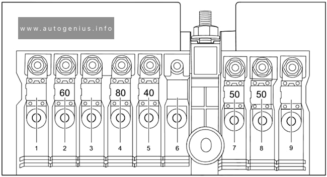
| F01 |
80A Black |
|
2018-2018: Rad Fan Control Module – If Equipped (DS 1500 Only)
2019-2024: Spare |
| F02 |
60A Yellow |
|
2018-2021: ABS Pump Motor (HD Only)
2022-2024: ABS Pump Mtr |
| F03 |
60A Yellow |
|
Rad Fan HI/Lo (if Equipped) |
| F04 |
50A Red |
|
2019-2024: 400W Inverter |
| F05 |
40A Green / 50A Red |
|
Air Suspension Comp |
| F06 |
40A Green |
|
2018: Antilock Brakes / Electronic Stability Control Pump
2019: ABS Pump Motor (DS 1500 Only)
2020-2024: Steering Torque Overlay Module (STOM) |
| F07 |
40A Green |
|
Starter Solenoid |
| F08 |
20A Blue |
|
2018: Emissions Diesel – If Equipped
2019: NOX Sensor – If Equipped; Aux Relay Output – SSV Only
2020-2024: NOX Sensor (if Equipped) |
| F09 |
30A Pink / 40A Green |
|
2018: Diesel Fuel Heater – If Equipped
2019: Aux Relay Output / Diesel Fuel Heater – If Equipped
2020-2024: Gas – Brake Vacuum Pump (if Equipped) / Diesel – Fuel Heater (if Equipped) |
| F10 |
40A Green / 50A Red |
|
Body Controller / Exterior Lighting #2 |
| F11 |
30A Pink / 40A Green |
|
2018: Integrated Trailer Brake Module – If Equipped
2019-2024: Brake System Module (ECU and Valves) |
| F12 |
40A Green |
|
Body Controller #3 / Power Locks |
| F13 |
40A Green |
|
HVAC Blower Motor |
| F14 |
40A Green |
|
Body Controller #4 / Exterior Lighting |
| F15 |
30A Pink |
|
2019-2024: Power Side Step (if Equipped) |
| F16 |
30A Pink |
|
Smart-Bar Module (if Equipped) |
| F17 |
30A Pink |
|
2019-2024: Winch Control Module – If Equipped |
| F18 |
|
|
Spare |
| F19 |
20A Blue / 30A Pink |
|
Diesel SCR Feed (if Equipped) |
| F20 |
30A Pink |
|
Passenger Door Mod |
| F21 |
30A Pink |
|
Drive Train Control Module |
| F22 |
20A Blue / 25A White / 30A Pink |
|
2018: Engine Control Module
2019: Engine Control Module GPEC / Heavy Duty / Other – If Equipped
2020-2024: Gas – ECM (if Equipped) / Diesel – PCM (if Equipped) |
| F23 |
30A Pink |
|
Body Controller #1 / Interior Lighting |
| F24 |
30A Pink |
|
Driver Door Mod |
| F25 |
30A Pink |
|
Front Wiper |
| F26 |
30A Pink |
|
2018-2019: Antilock Brakes / Stability Control Module / Valves – If Equipped
2020-2024: Spare |
| F27 |
|
|
Spare |
| F28 |
20A Blue |
|
Trailer Tow Backup Lights – If Equipped |
| F29 |
20A Blue |
|
Trailer Tow Parking Lights – If Equipped |
| F30 |
30A Pink |
|
2018: Trailer Tow Receptacle
2019-2021: Trailer Tow Receptacle / Trailer Tow (Separate E-Brake) / Trailer Tow (BUX)
2022-2024: Trailer Tow |
| F31 |
30A Pink |
|
2018: Urea Heater Control – If Equipped
2019: Diesel Heater Control – If Equipped (DS 1500 LD Diesel)
2020-2024: Spare |
| F32 |
|
|
Spare |
| F33 |
20A Blue |
|
2018: Special Services Vehicle Only
2019-2024: Transmission Control Module (if Equipped) |
| F34 |
30A Pink |
|
Vehicle System Interface Module #2 (if Equipped) |
| F35 |
30A Pink |
|
Sunroof (if Equipped) |
| F36 |
30A Pink |
|
Rear Defroster (EBL) (if Equipped) |
| F37 |
30A Pink |
|
2018: Cummins Diesel Fuel Heater #2 (If Equipped)
2019: Fuel Heater #2, Aux Relay 2 – If Equipped (HD Only); SSV (DS 1500 Only)
2020-2024: Diesel Frame / Fuel Heater (if Equipped) |
| F38 |
30A Pink |
|
2018: Power Inverter 115V AC (If Equipped)
2019: Integrated Trailer Brake Module – If Equipped (HD Only); Power Inverter 115V AC – If Equipped (DS 1500 Only)
2020-2024: Integrated Trailer Brake Module (if Equipped) |
| F39 |
20A Blue |
|
2018-2019: Power Outlet – Special Services Only
2020-2024: Spare |
| F40 |
|
10A Red |
2019-2024: Ventilated Seats (if Equipped) |
| F41 |
|
10A Red |
2018: Active Grille Shutter (If Equipped)
2019-2024: Active Grille Shutter / Active Air Dam (if Equipped) |
| F42 |
|
20A Yellow |
Horn |
| F43 |
|
15A Blue |
2019-2024: Heated Steering Wheel (if Equipped) |
| F44 |
|
10A Red |
Diagnostic Port |
| F45 |
|
|
Spare |
| F46 |
|
10A Red |
Upfitters Relay Coils (if Equipped) |
| F47 |
|
|
Spare |
| F48 |
|
|
Spare |
| F49 |
|
10A Red / 15A Blue |
2018: Instrument Panel Cluster (Except Fleet Vehicles)
2019: Instrument Panel Cluster / HVAC (DS 1500 Only); Instrument Cluster / MOD CSG (HD Only)
2020-2024: IP Cluster / CSG |
| F50 |
|
20A Yellow |
Air Suspension Control Module (if Equipped) |
| F51 |
|
10A Red |
2018-2021: Ignition Node Module / Keyless Ignition Node Module, Radio Frequency Hub Module / Electric Steering Column Lock
2022-2024: Ignition Node Module / Keyless Ignition Node Module, Radio Frequency Hub Module |
| F52 |
|
5A Tan |
Battery Sensor |
| F53 |
|
20A Yellow |
Trailer Tow – Left Turn/Stop Lights |
| F54 |
|
20A Yellow |
Non Memory Adjustable Pedals (if Equipped) |
| F55 |
|
10A Red |
2023-2024: Fwd Utility Lamps |
| F56 |
|
10A Red / 15A Blue |
2018-2019: Additional Diesel Content (If Equipped)
2020-2024: Fuel Vapor Blocking Valve (VBV) |
| F57 |
|
20A Yellow |
TCM / PCM / Solenoid Trans Pressure SW |
| F58 |
|
10A Red |
2019-2024: Bed Lighting (LED) |
| F59 |
|
|
Spare |
| F60 |
|
15A Blue |
2018: Underhood Lamp
2019: Underhood Lamp / TCM – If Equipped (DS 1500 Only)
2020-2024: Spare |
| F61 |
|
10A Red |
2018: PM Sensor (If Equipped)
2019: UREA Sensor / PM Sensor – If Equipped (DS 1500 LD Diesel & Cummins Diesel)
2020-2024: NH3 Sensor / PM Sensor (if Equipped) |
| F62 |
|
10A Red |
Air Conditioning Clutch |
| F63 |
|
20A Yellow |
2018: Ignition Coils (Gas), Urea Heater (Cummins Diesel)
2019: Ignition Coils (Gas), Ignition Coils Capacitors (Gas) / Short Runner Valve Actuator / Urea Heater Control Unit (DS 1500 LD Diesel) / RLY Coil Feed-SCR (DS 1500 LD Diesel)
2020-2024: Ignition Coils / CAPS |
| F64 |
|
25A Clear |
Fuel Injectors / PCM (if Equipped) |
| F65 |
|
10A Red |
2018: Spare
2019-2021: MOD Inverter (Wake Up) / Power Port / USB IP / WCPM – If Equipped (HD Only)
2022: Spare
2023-2024: RVDMP / MOD BLE (if Equipped) |
| F66 |
|
10A Red |
2018: Sunroof / Passenger Window Switches / Rain Sensor
2019: Sunroof / Light and Rain Sensor Module / Inside Rearview Mirror / Passenger Window SW / USB Port Rear / Feed for R/A RLY #2 Coil (If Equipped)
2020-2021: Sunroof / USB Rear (If Equipped)
2022-2024: Sunroof / USB Rear / Inside Rearview Mirror/ Passenger Window SW |
| F67 |
|
10A Red |
2018: CD / DVD / Bluetooth Hands-free Module (If Equipped)
2019: CD / DVD / UCI Port – If Equipped (HD Only); Bluetooth Hands-Free Module / CD – If Equipped (DS 1500 Only)
2020: CDM / UCI Port / USB Front
2021: UCI Port / USB Front
2022: UCI Port / USB Front / Trailer Gateway Module (360 Camera) / Tachograph
2023-2024: UCI Port / Trailer Gateway Module (360 Camera) / Tachograph |
| F68 |
|
10A Red |
2019-2024: AEB RACAM HTR (if Equipped) |
| F69 |
|
15A Blue |
SCR Mod 12 Volt (if Equipped) |
| F70 |
|
30A Green |
2018: Fuel Pump Motor
2019-2021: Fuel Pump Motor / K09 RLY Coil Feed (If Equipped)
2022-2024: Fuel Pump Mtr / Fuel Htr RLY |
| F71 |
|
25A Clear |
2018: Amplifier
2019-2024: Amplifier / Active Noise Cancelation |
| F72 |
|
10A Red |
2018: PCM (If Equipped)
2019: PCM / DC/DC Converter Voltage – If Equipped (DS 1500 Only)
2020-2024: Spare |
| F73 |
|
20A Yellow |
Fuel Transfer Pump (if Equipped) |
| F74 |
|
20A Yellow / 10A Red |
2018-2019: Brake Vacuum Pump Gas/Diesel (If Equipped)
2020-2024: Backup Alarm |
| F75 |
|
10A Red |
2018: Coolant Temperature Valve Actuator
2019: ATMM / Coil-SCR Module RLY – If Equipped (HD Only); Coolant Temperature Valve – If Equipped (DS 1500 Only)
2020-2024: ATMM / Coil-SCR Module RLY (if Equipped) |
| F76 |
|
10A Red |
2018: Antilock Brakes / Electronic Stability Control
2019: Electronic Stability Control (HD Only); Brake System Module / Stop Lamp Switch / Electric Park Brake / Clutch Pedal Switch (DS 1500 Only)
2020-2024: Electronic Stability Control (ESC) (if Equipped) |
| F77 |
|
10A Red |
2018: Drivetrain Control Module / Front Axle Disconnect Module
2019: Drivetrain Control Module / Front Axle Disconnect Module / TCM (HD Only); Drivetrain Control Module / ELSD / Front Axle Disconnect Module / Transmission Control Relay / RDM / Power Take Off Unit – If Equipped (DS 1500 Only)
2020-2024: Drivetrain Control Module / Front Axle Disconnect Module / TCM / STOM |
| F78 |
|
10A Red / 15A Blue |
2018: Engine Control Module / Electric Power Steering
2019: Engine Control Module / Powertrain Control Module / AEB RACM MOD / Feed To AUX PDC Relay Coils (HD Only)
2020-2021: Engine Control Module / Powertrain Control Module / AEB RACM MOD / Feed To AUX PDC Relay Coils / HRLS
2022-2024: ECM / PCM / IRCM / AUX Relay Feed / HRLS |
| F79 |
|
15A Blue |
2018: Clearance Lights
2019-2024: ID / Clearance Lt |
| F80 |
|
10A Red |
2018: Universal Garage Door Opener / Compass
2019: Universal Garage Door Opener/Compass/Anti-Intrusion Module (DS 1500 Only); ASSY Overhead Console / SW Assist / SW 911 – If Equipped (HD Only)
2020-2024: Overhead Console / Assist / 911 |
| F81 |
|
20A Yellow |
Trailer Tow Right Turn/Stop Lights |
| F82 |
|
10A Red |
Steering Column Control Module / Cruise Control |
| F83 |
|
10A Red |
2023-2024: TLR AST / TLR RVS CTL / TLR KNB |
| F84 |
|
15A Blue |
2018: Switch Bank / Instrument Cluster
2019-2024: ASBM / HVAC / ICS / Rear Heated Seat Switches |
| F85 |
|
10A Red |
ORC (Airbag) |
| F86 |
|
10A Red |
ORC (Airbag) |
| F87 |
|
10A Red |
2018: Air Suspension – If Equipped / Trailer Tow / Steering Column Control Module
2019: Air Suspension / ITBM / Steering Column Control Module / MOD Gateway CAN-C Trailer TPM (HD Only); Air Suspension / Trailer Tow / DC/DC Converter (Voltage Stabilizer) / Steering Column Control Module / Occupant Classification Sensor (DS 1500 Only)
2020-2021: Air Suspension / ITBM / Steering Column Control Module / MOD Gateway CAN-C Trailer TPM
2022-2024: Air Susp / ITBM / SCCM / TLR TPM |
| F88 |
|
15A Blue |
Instrument Panel Cluster |
| F89 |
|
|
Spare |
| F90 |
|
20A Yellow |
Power Outlet / Batt (Customer Selectable) |
| F91 |
|
20A Yellow |
Power Outlet / Acc (Customer Selectable) |
| F92 |
|
10A Red |
2023-2024: Invertor MOD / USB-IP / WCPM (if Equipped) |
| F93 |
|
20A Yellow |
2018-2019: Cigar Lighter |
| F94 |
|
10A Red |
2018: Shifter / Transfer Case Module
2019: Shift-By-Wire / Transfer Case Switch (DS 1500 Only); Shift-By-Wire/Transfer Case Switch / Module TPM Trailer (HD Only) / Module Gateway Can-C Trailer TPM (HD Only)
2020-2022: Shift-By-Wire / Transfer Case Switch / Module TPM Trailer / Module Gateway Can-C Trailer TPM
2023-2024: SBW / TCASE SW / TRL TPM – GTWY |
| F95 |
|
10A Red |
2018: Rear Camera / Park Assist
2019: Rearview Camera / Park Assist / CHMSL Camera / Blind Spot Sensor / Surround View Camera (HD Only) Rear Camera / Park Assist/ Blind Spot Sensor / Compass (DS 1500 Only)
2020-2024: Rearview Camera / Park Assist / CHMSL Camera / Blind Spot Sensor / Surround View Camera |
| F96 |
|
10A Red |
2018: Rear Seat Heater Switch
2019: Rear Seat Heater Switch / Trunk Lamp With Flashlamp Charger / Truck Lamp – If Equipped (DS 1500 Only); Trailer Camera – If Equipped (HD Only)
2020-2024: Trailer Camera (if Equipped) |
| F97 |
|
20A Yellow / 25A Clear |
2018-2019: Rear Heated Seats & Heated Steering Wheel (If Equipped)
2020-2024: Front Heated Seat Passenger (if Equipped) |
| F98 |
|
20A Yellow / 25A Clear |
2018-2019: Front Heated Seats (If Equipped)
2020-2024: Front Heated Seat Driver (if Equipped) |
| F99 |
|
10A Red |
2018: Climate Control
2019: HVAC / DASM (DS 1500 Only); HVAC/ In-Car Temperature Sensor / CSG MOD / Humidity Sensor (HD Only)
2020-2021: HVAC / In-Car Temperature Sensor / CSG MOD
2022-2024: HVAC / In-Car Temperature Sensor / CSG MOD / Module Gateway Trailer / Tachograph |
| F100 |
|
10A Red |
Upfitter Box Feed (if Equipped) |
| F101 |
|
20A Yellow |
2018: Electrochromatic Mirror / Smart High Beams (If Equipped)
2019: SSV Only
2020-2024: Rear Heated Seat Right (if Equipped) |
| F102 |
|
20A Yellow |
2019-2024: Rear Heated Seat Left / Run RLY #3 Coil (if Equipped) |
| F103 |
|
10A Red |
HeadLamp AFLS (if Equipped) |
| F104 |
|
20A Yellow |
2018: Power Outlets (Instrument Panel / Center Console)
2019: Power Outlets (Instrument Panel / Center Console) / Trunk – If Equipped (DS 1500 Only); UCI Port / USB Rear (HD Only)
2020-2024: UCI Port / USB Rear |