This article focuses on the seventh-generation Volkswagen Jetta (A7), produced from 2019 to the present. It includes fuse box diagrams for the facelifted 2022, 2023 and 2024 Volkswagen Jetta A7 models, details on the location of the fuse panels inside the vehicle, and an overview of the fuse assignments (fuse layout) and relay functions.
Steering Column Electronics Control Module
Ignition/Starter Switch
SC10
7.5A
Front Information Display Control Head
SC11
40A
Vehicle Electrical System Control Module (exterior lighting on the left side)
SC12
20A
Information Electronics Control Module 1
SC13
–
–
SC14
40A
Fresh Air Blower Control Module
SC15
10A
Electronic Steering Column Lock Control Module
SC16
7.5A/10A
Storage Compartment with Cell Phone Interface
USB Charging Socket 1 (from 2023)
USB Connection 1
SC17
7.5A
Instrument Cluster
Control Module for Emergency Call Module and Communication Unit
SC18
7.5A
Rearview Camera
SC19
7.5A
Access/Start System Interface
SC20
15A
Vacuum Pump Relay
SC21
–
–
SC22
–
–
SC23
20A
Sunroof Control Module
SC24
40A
Vehicle Electrical System Control Module (exterior lighting on the right side)
SC25
30A
Driver Door Control Module
Left rear window regulator motor
SC26
30A
Vehicle Electrical System Control Module (seat heating)
SC27
30A
Vehicle Electrical System Control Module (interior lighting)
SC28
–
–
SC29
5A
Refrigerant Circuit Pressure Sensor
SC30
10A
Remote Start System Relay
SC31
–
–
SC32
7.5A
Blind Spot Detection Control Module
Blind Spot Detection Control Module 2
Parking Aid Control Module
Driver Assistance Systems Front Camera
Control Module for Adaptive Cruise Control
SC33
7.5A
Airbag Control Module
Front Passenger Airbag “Disabled” Indicator Lamp
Passenger Occupant Detection System Control Module
SC34
7.5A
Refrigerant Circuit Pressure Sensor
Center console switch module 1
Interior Rearview Mirror
Rotary Light Switch
Back-up lamp switch
Structure borne sound control module
Air Quality Sensor
Rear Seat Heating Control Module
Center Console Switch Module 2
Sockets Relay
Refrigerant Circuit Pressure Sensor
Parking Brake Button
SC35
7.5A
Diagnostic Connection
SC36
–
–
SC37
–
–
SC38
–
–
SC39
30A
Front Passenger Door Control Module
Right Rear Window Regulator Motor
SC40
20A
12V Socket
Sockets Relay
SC41
–
–
SC42
40A
Vehicle Electrical System Control Module (central locking system)
SC43
30A
Digital Sound System Control Module
SC44
–
–
SC45
15A
Left Front Seat Adjustment Control Head
Driver Seat Lumbar Support Adjustment Switch
Left Front Seat Cushion Fan 1
Left Front Seat Backrest Fan 1
Driver Seat Adjustment Control Module
SC46
7.5A
USB Charging Socket 1 (2022)
SC47
–
–
SC48
–
–
SC49
7.5A
Starter Relay 1
Starter Relay 2
Clutch Position Sensor Remote Start System Relay
Remote Start System Relay (2022)
SC50
–
–
SC51
25A
Rear Seat Heating Control Module
Driver Power Seat Adjustment Circuit Breaker 1
SC52
15A
Electronic Damping Control Module
SC53
30A
Rear Window Defogger Relay
R1
Vacuum Pump Relay
R2
A/C Clutch Relay
R3
Windshield Defogger Relay
R4
Terminal 15 Power Supply Relay
R5
Rear Window Defogger Relay
R6
Sockets Relay
F59
15A/30A
2010-2012:
Amplifier
2013-2017:
Fan activation relay (Engine code CNLA)
Battery fan 1 (Engine code CNLA)
F60
30A
Auxiliary heater control module
–
20A
Driver power seat adjustment circuit breaker 1 (it is located above relay carrier)
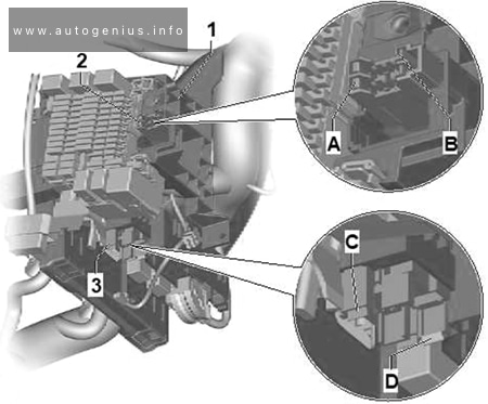
Individuals fuses
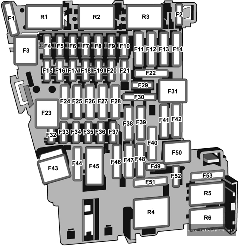
Volkswagen Jetta (A7; 2022 – 2024) – fuse and relay diagram – passenger compartment (Individual fuses)Assignment of the fuses in the Individual fuses
№
Amps
Function / Component
A
–
–
B
15A
Right Front Seat Backrest Fan 1
Right Front Seat Cushion Fan 1
C
7.5A
Passenger Occupant Detection System Control Module
This article covers the pre-facelift second-generation Volkswagen Tiguan (AD/BW), manufactured from 2016 to 2020. It includes fuse box diagrams for the 2017, 2018, 2019, and 2020 models, details the locations of the fuse panels inside the vehicle, and explains the function of each fuse (fuse layout).
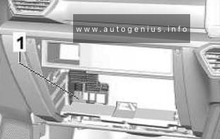
Instrument panel fuse box
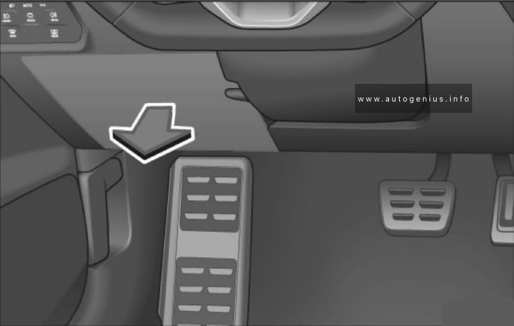
Fuse Box Location
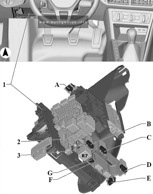
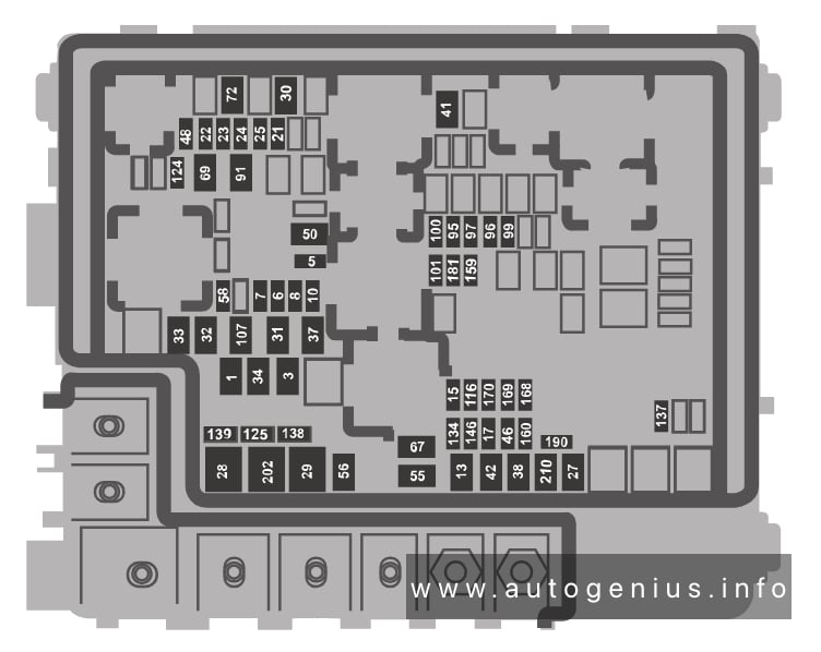
Volkswagen Tiguan – fuse and relay location – passenger compartment
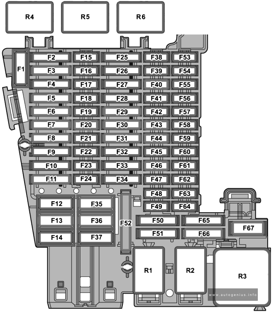
Fuse Box Diagram (-SC-)
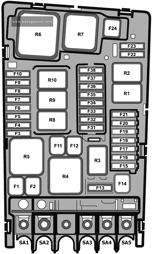
Volkswagen Tiguan – fuse and relay diagram – passenger compartment (holder C)
Assignment of the fuses in the instrument panel fuse box (fuse holder C-SC-)
№
Amps
Function / Component
SC1
20A
Reducing Agent Heater Control Module
SC2
10A
Steering Column Electronics Control Module
SC3
–
–
SC4
7.5A
Alarm Horn
SC5
7.5A
Remote Start System Relay
Data Bus on Board Diagnostic Interface
SC6
7.5A
AT Selector Mechanism
Ignition Switch Key Lock Solenoid
SC7
10A
Rear A/C Display Control Head
Tire Pressure Monitoring Control Module
Auxiliary Coolant Heater Radio Frequency Receiver
A/C Clutch Relay
Rear Window Defogger Relay
SC8
7.5A
Driving Profile Selection Control Head
Parking brake button
Rain/Light Recognition Sensor
Anti-Theft Alarm System Sensor
Cornering Lamp and Headlamp Range Control Module
Left Rear Door Ambient Lighting Bulb 1
Right Rear Door Ambient Lighting Bulb 1
Left Front Door Ambient Lighting Bulb 1
Right Front Door Ambient Lighting Bulb 1
Diagnostic Connection
SC9
7.5A
Steering Column Electronics Control Module
Ignition/Starter Switch
SC10
7.5A
Front Information Display Control Head
Windshield Projection Head Up Display Control Module
SC11
40A
Vehicle Electrical System Control Module (exterior lighting on the left side)
SC12
20A
Information Electronics Control Module 1
SC13
25A
Left Front Seat Belt Tensioner Control Module
SC14
40A
Fresh Air Blower Control Module
SC15
10A
Electronic Steering Column Lock Control Module
SC16
7.5A/10A
Mobile communication 2-way signal amplifier
USB Connection 1
USB Charging Socket 1 (2023)
Storage Compartment with Cell Phone Interface
SC17
7.5A
Control Module for Emergency Call Module and Communication Unit
Instrument Cluster
SC18
7.5A
Rear Lid Handle
Peripheral Camera Control Module
SC19
7.5A
Access/Start System Interface
SC20
15A/10A
Vacuum Pump Relay
Reducing Agent Metering System Relay
SC21
15A
All Wheel Drive Control Module
SC22
15A
Towing Recognition Control Module
SC23
20A
Sunroof Control Module
SC24
40A
Vehicle Electrical System Control Module (exterior lighting on the right side)
SC25
30A
Driver Door Control Module
SC26
30A
Vehicle Electrical System Control Module (seat heating)
SC27
30A
Vehicle Electrical System Control Module (interior lighting)
SC28
25A
Towing Recognition Control Module (left)
SC29
7.5A
Remote Start System Relay
Refrigerant Circuit Pressure Sensor
SC30
10A
Remote Start System Relay
SC31
30A
Rear Lid Control Module
SC32
7.5A
Parking Aid Control Module
Lane Change Assistance Control Module 2
Driver Assistance Systems Front Camera
Lane Change Assistance Control Module
Control Module for Adaptive Cruise Control
SC33
7.5A
Airbag Control Module
Front Passenger Airbag -Disabled- Indicator Lamp
Engine Component Power Supply Relay (2.0L gasoline)
SB17
7.5A
ABS Control Module
Windshield Defogger Relay
Engine/Motor Control Module
Motronic Engine Control Module Power Supply Relay
Terminal 30 Power Supply Relay
SB18
7.5A
Data Bus on Board Diagnostic Interface (vehicles without parking heater)
Battery Monitoring Control Module (vehicles with parking heater)
SB19
30A
Windshield Wiper Motor
SB20
–
–
SB21
15A
Transmission Control Module
Dual-Clutch Transmission Mechatronic
SB22
7.5A
Engine/Motor Control Module
SB23
30A
Starter
SB24
40A
Auxiliary Heater Heating Element
SB25
–
–
SB26
–
–
SB27
–
–
SB28
–
–
SB29
–
–
SB30
–
–
SB31
–
–
SB32
–
–
SB33
–
–
SB34
10A
Windshield Defogger Relay (4GT)
SB35
–
–
SB36
15A
Left Front Headlamp
SB37
20A
Auxiliary Heater Control Module (vehicles with parking heater)
SB38
15A
Right Front Headlamp
SA1
125A
Supply for Fuses (Passenger Compartment):
Fuse 1 (on fuse panel C)
Fuse 2 (On Fuse Panel C)
Fuse 5 (On Fuse Panel C)
Fuse 14 (On Fuse Panel C)
Fuse 22 (On Fuse Panel C)
Fuse 32 (On Fuse Panel C)
Fuse 42 (On Fuse Panel C)
Fuse 46 (On Fuse Panel C)
Fuse 47 (On Fuse Panel C)
Fuse 49 (On Fuse Panel C)
Fuse 51 (On Fuse Panel C)
Fuse 53 (On Fuse Panel C)
SA2
400A
Generator with Voltage Regulator
508
Battery
SA3
80A
Power Steering Control Module
SA4
80A
Supply for Fuses (Passenger Compartment):
Fuse 3 (On Fuse Panel C)
Fuse 15 (On Fuse Panel C)
Fuse 20 (On Fuse Panel C)
Fuse 23 (On Fuse Panel C)
Fuse 28 (On Fuse Panel C)
Fuse 43 (On Fuse Panel C)
Fuse 45 (On Fuse Panel C)
Fuse 50 (On Fuse Panel C)
SA5
50A
Radiator Fan
R1
Starter Relay 1
R2
Starter Relay 2
R3
Horn Relay
R4
Secondary air injection pump relay (2.0L gasoline)
R5
Motronic Engine Control Module Power Supply Relay (gasoline)
R6
–
R7
–
R8
Engine Component Power Supply Relay
R9
Windshield Defogger Relay
R10
Windshield Defogger Relay
WARNING: Terminal and harness assignments for individual connectors will vary depending on vehicle equipment level, model, and market.
The Cupra Formentor, a compact crossover, has been in production from 2020 to the present. This article provides fuse box diagrams for the 2020, 2021, and 2022 models, along with details about the locations of the fuse panels within the vehicle and the functions of each fuse (fuse layout) and relay.
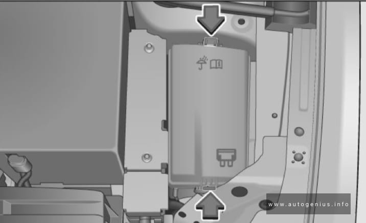
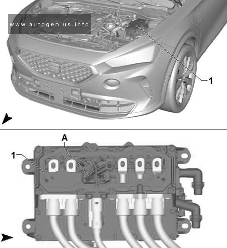
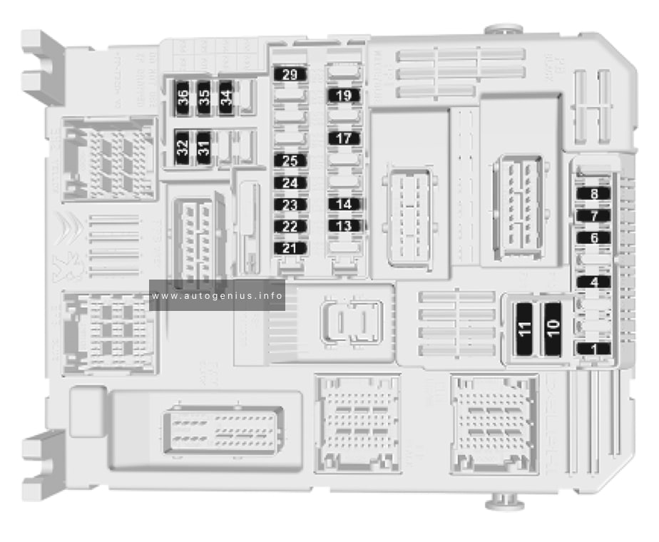
Passenger Compartment Fuse Box
Fuse Box Location
Left-hand drive vehicles: The fuse panel is behind the cover. Fold the cover down to access.
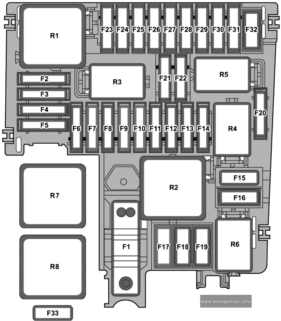
Cupra Formentor (2020 – 2022) – fuse and relay box diagram – passenger compartment (holder C)
Assignment of the fuses in the instrument panel (Fuse holder C)
№
Amps
Function/component
SC1
–
–
SC2
–
–
SC3
25A
Trailer detector control unit
SC4
20A
SCR, Adblue
SC5
25A
Parking lock sender
Parking lock actuator
SC6
30A
Onboard supply control unit (interior light)
SC7
30A
Heated deats
Heater and air conditioning controls
Heater and air conditioning system control unit
SC8
20A
Sliding sunroof adjustment control unit
SC9
30A
Driver door control unit (LHD)
Rear left door control unit
Front passenger door control unit (RHD)
SC10
–
–
SC11
15A
Trailer detector control unit
SC12
40A
Onboard supply control unit (right lights)
SC13
40A
Onboard supply control unit (central locking)
SC14
30A
Digital sound package amplifier
SC15
–
–
SC16
7.5A
Airbag control unit
SC17
10A
Relay for reducing agent metering system
SC18
7.5A
Interface for entry and start system (KESSY)
Control unit 2 for break-in protection
Control unit 3 for break-in protection
Control unit for electronic steering column lock
Control unit 5 for break-in protection
Control unit 4 for break-in protection
Driver exterior door handle
SC19
7.5A
Emergency call module control unit and communication unit
Dash panel insert
SC20
7.5A
Storage compartment with interface for mobile telephone
Transmission and reception stabilisation control unit
USB connection 1
SC21
7.5A
Rear overhead view camera
Control unit for overhead view camera
Blind spot monitor control unit
Blind Spot Monitor control unit 2
Rear lid power opening control unit
SC22
–
–
SC23
–
–
SC24
15A
All-wheel drive control unit
SC25
25A
Front left seat belt (LHD)
Front right seat belt (RHD)
SC26
30A
Front passenger door control unit (LHD)
Rear right door control unit
Driver door control unit (RHD)
SC27
25A
Front left seat belt (LHD)
Front right seat belt (RHD)
SC28
10A
Hybrid battery unit
Pilot line connector 1
SC29
15A
Trailer detector control unit
SC30
20A
Multimedia system
Control unit 1 for information electronics
SC31
25A
Trailer detector control unit
SC32
–
–
SC33
–
–
SC34
30A
DC/AC converter with socket, 12V – 230V
SC35
40A
Onboard supply control unit (left lights)
SC36
40A
Fresh air blower control unit
SC37
30A
Rear lid control unit
SC38
–
–
SC39
10A
Heated steering wheel
Steering column electronics control unit
SC40
7.5A
Alarm horn
Anti-theft alarm system horn
SC41
7.5A
Data bus diagnostic interface
SC42
7.5A
Selector mechanism
Selector lever position display
Control unit for electronic steering column lock
SC43
10A
Operating and display unit for rear air conditioning system
Heater and air conditioning controls
Heater and air conditioning system control unit
Vehicle interior temperature sensor
Heated rear window relay
Heater and air conditioning system control unit
SC44
7.5A
Switch module 1 in centre console
Operating unit for lighting
Air humidity, rain and light detector sensor
Front roof module
Anti-theft alarm sensor
Diagnostic connection
SC45
7.5A
Steering column electronics control unit
SC46
7.5A
Display unit for front information display and operating unit control unit
SC47
15A
Electronically controlled damping control unit
SC48
7.5A
USB charging socket 1
SC49
–
–
SC50
–
–
SC51
–
–
SC52
20A
12V socket
12V socket 2
SC53
–
–
SC54
–
–
SC55
–
–
SC56
–
–
SC57
–
–
SC58
7.5A
Parking aid control unit
Adaptive cruise control unit
Front camera for driver assist systems
SC59
7.5A
Switch module 1 in centre console
Relay for power sockets
Air quality sensor
Pressure sender for refrigerant circuit
Interior mirror
Reversing light switch
Control unit for structure-borne sound
SC60
7.5A
Diagnostic connection
SC61
7.5A
Hybrid battery unit
Power and control electronics for electric driveDNFB:
Starter relay 1
Starter relay 2DNWB:
Terminal 15 voltage supply relay
DNNA:
Starter relay 2
SC62
–
–
SC63
–
–
SC64
–
–
SC65
10A
Engine sound generator control unit
SC66
15A
Rear window wiper motor
SC67
30A
Amplitude modulation (AM) frequency filter
Frequency modulation (FM) frequency filter in positive wire
Heated rear window
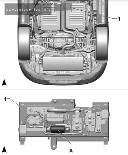
Cupra Formentor (2020 – 2022) – fuse and relay box diagram – engine compartment (holder B)
Assignment of the fuses in the engine compartment (Fuse holder B)
№
Amps
Function/component
SB1
80A
Power steering control unit
SB2
7.5A
ABS control unit
DGEA, DNNA:
Main relay
Engine control unit
SB3
7,5A/10A/20A
Charging unit 1 for high-voltage battery
Power and control electronics for electric drive
Fuel pump control unitDNFB, DNNA:
Engine component current supply relayDNWB:
Starter relay 2
SB4
15A
Front left headlight
SB5
15A
Front right headlight
SB6
–
–
SB7
30A
Gearbox oil cooling pump
SB8
40A
Brake servo
SB9
15A
Horn relay
SB10
30A
Windscreen wiper motor
SB11
7,5A
Engine component current supply relay (PHEV Climate)
SB12
30A/15A
Mechatronic unit for dual clutch gearbox
SB13
25A
ABS control unit
SB14
20A
Engine component current supply relay (Heater)
SB15
40A
ABS control unit
SB16
50A
Mechatronic unit for dual clutch gearbox / PHEV
SB17
40A/50A
Auxiliary air heater element
SB18
40A
Auxiliary air heater element
SB19
–
–
SB20
15A
Axle differential lock control unit
SB21
7.5A
Engine control unit
SB22
30A
Starter
SB23
15A
Engine control unit
SB24
7,5A/10A
Regeneration air blower
Oil level and oil temperature sender
Radiator fan
Engine component current supply relayDGEA:
Activated charcoal filter solenoid valve 1
Exhaust camshaft control valve 1
Valve for oil pressure control
Inlet camshaft control valve 1DNFB:
Activated charcoal filter solenoid valve 1
Intake manifold flap valve
Camshaft control valve 1
Turbocharger air recirculation valve
Exhaust camshaft control valve 1
Valve for oil pressure control
Inlet camshaft control valve 1
DNFB:
Cam adjustment actuator 1~8DGEA:
Coolant circulation pump before power and control electronics for electric drive
Heater coolant shut-off valve
Coolant valve for gearbox
Coolant changeover valve 1DNWB:
Coolant shut-off valve
Solenoid for coolant circuit
SB26
7,5A/10A
DNFB:
Coolant valve for gearbox
Exhaust flap control unit
Exhaust flap control unit 2
Coolant circulation pumpDGEA:
Charge air cooling pumpDNWB:
Camshaft control valve 1
Exhaust camshaft control valve 1
Engine/motor control unit
Exhaust cam actuator for cylinder 1~5
DNNA Coolant circulation pump
SB27
10A/15A
Lambda probe 1 after catalytic converter
Lambda probe 1 before catalytic converter
SB28
10A/20A
2021-2022: Ignition coil 1~4 with output stage
SB29
15A/20A/30A
Fuel pump control unit
SB30
10A
Coolant pump for low-temperature circuit 2
DGEA:
Auxiliary pump for heating
Fuel tank shut-off valve
DNWB:
Oil level and oil temperature sender
Charge pressure control solenoid valve
Turbocharger air recirculation valve
Crankcase breather valve
Intake manifold flap valve
Activated charcoal filter solenoid valve 1
SB31
–
–
SB32
–
–
SB33
40A
Auxiliary air heater element
R1
Main relay (petrol)
Terminal 30 voltage supply relay (diesel)
R2
High heat output relay (diesel)
Secondary air pump relay (petrol 2.0L/2.5L)
R3
Horn relay
R4
Starter relay 1
R5
Starter relay 2
R6
Engine component current supply relay (petrol 2.0L/2.5L)
Fuel pump relay (petrol 1.5L)
Air conditioning system relay (hybrid)
R7
Automatic glow period control unit (diesel)
R8
Low heat output relay (diesel)
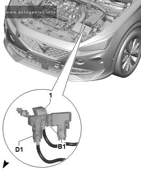
Connection and Distribution Box 2 (SX2)
Cupra Formentor (2020 – 2022) – fuse and relay box diagram – engine compartment (Connection and Distribution Box 2 (SX2)))
Assignment of the fuses in the engine compartment (Connection and Distribution Box 2 (SX2))
№
Amps
Function/Component
B1
–
Supply fuse holder A
D1
400A
Starter
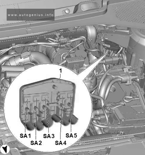
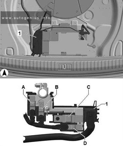
Fuse Holder A (Hybrid drive)
Cupra Formentor (2020 – 2022) – fuse and relay box diagram – engine compartment (Holder A (Hybrid drive))
Assignment of the fuses in the engine compartment (Holder A (Hybrid drive))
Jeep Grand Cherokee (WL; 2021 – 2024) – fuse and relay box diagram
Year of production: 2021, 2022, 2023, 2024
This article covers the fifth-generation Jeep Grand Cherokee (WL), available from 2021 to the present. It includes fuse box diagrams for the 2021, 2022, 2023 and 2024 Jeep Grand Cherokee models, provides information on the locations of the fuse panels inside the vehicle, and details the assignment of each fuse (fuse layout).
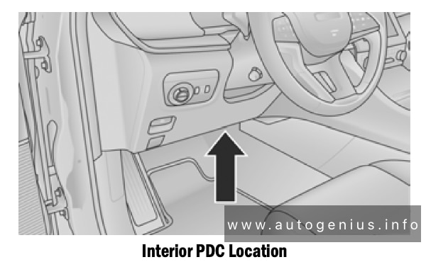
Passenger compartment fuse box
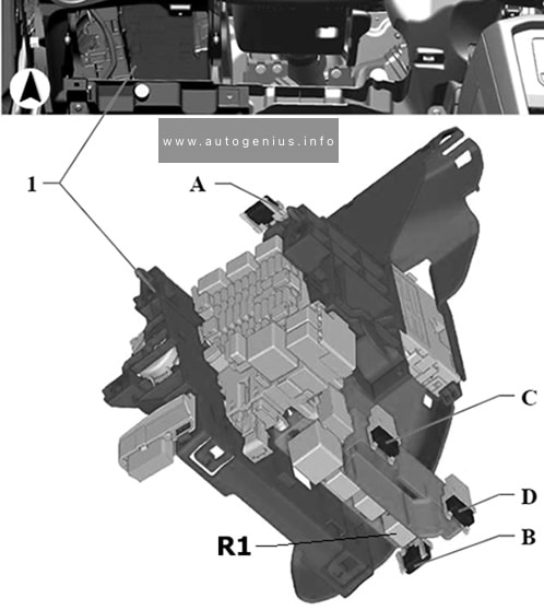
Fuse box location
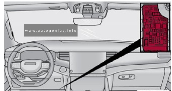
The Interior Power Distribution Center is located underneath the steering column on the driver’s side of the vehicle.
Jeep Grand Cherokee (WL; 2021 – 2024) – fuse and relay box location -passenger compartment
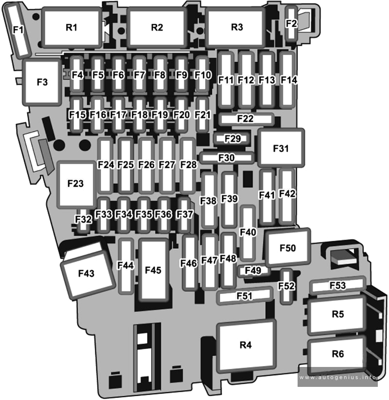
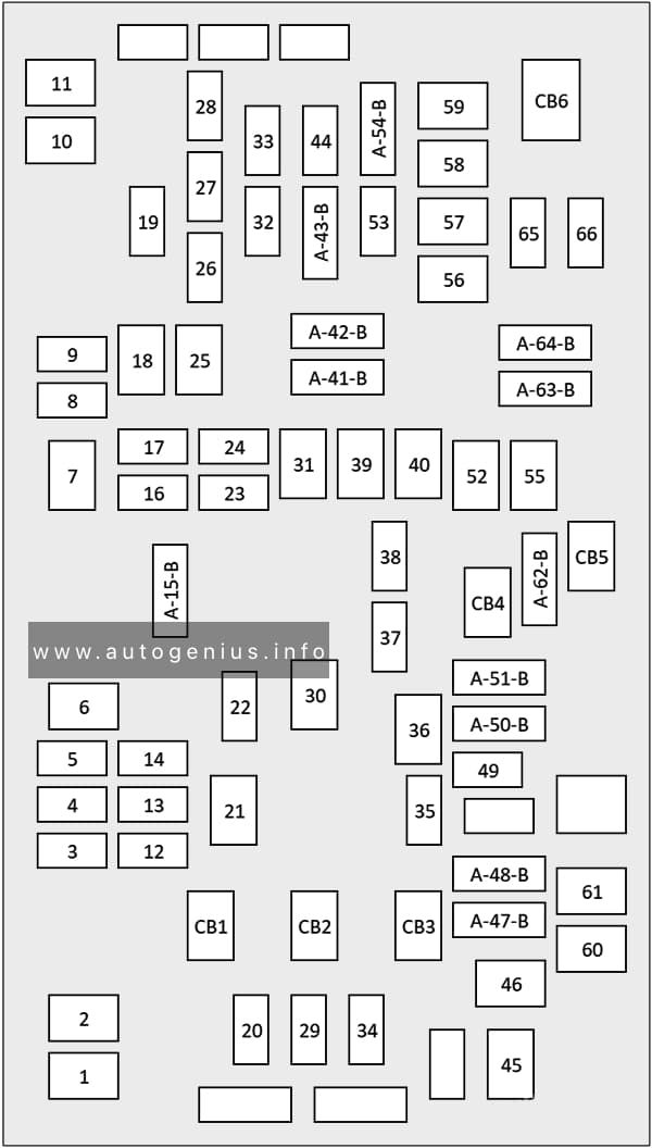
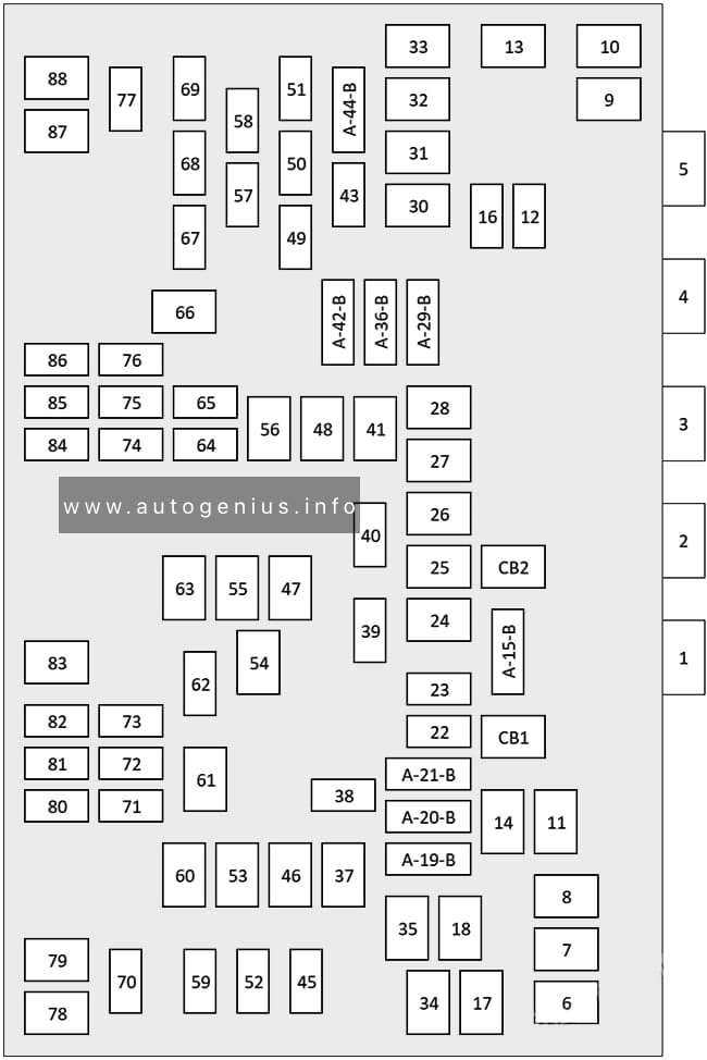
Fuse box diagram
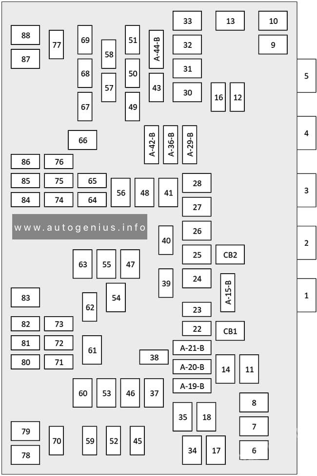
Jeep Grand Cherokee (WL; 2021 – 2024) – fuse and relay box diagram -passenger compartment
Assignment of the fuses and relay in the instrument panel
№
Cartridge Fuse
Micro Fuse
Description
F01
–
–
–
F02
25A Clear
–
MTR Sunshade Sunroof Dual Pane / MTR sunroof single Pane
F03
–
15A Blue
MOD Seat Heater Frt (Steering Wheel)
F04
–
10A Red
Night Vision Module / Driver Monitoring Camera (DMC)
Assy Mirror Inside Rearview / Digital TV (DTV) / Sunroof Single – Dual Pane / Port UC1 Dual USB RR / Interior Monitoring Camera
F14
–
–
–
F15A
–
–
–
F15B
–
–
–
F16
–
10A Red
MOD ORC
F17
–
–
–
F18
–
–
–
F19
–
–
–
F20
–
10A Red
Overhead Console Assy (OHC) W/Sunshade/ Intrusion Module / Intrusion Sensor/Siren/ Head Up Display (HUD) / Digital TV (DTV)
F21
30A Pink
–
Trailer Tow Electric Brake – Aftermarket
F22
–
–
–
F23
–
–
–
F24
–
–
–
F25
–
–
–
F26
–
–
–
F27
–
–
–
F28
–
–
–
F29
–
–
–
F30
–
–
–
F31
–
–
–
F32
–
15A Blue
MOD ICS Switch Bank/SW Bank Upper/ SW EPB / Aux Switch Bank Module (ASBM)
F33
–
15A Blue
Transfer case SW / Humidity Rain Light Sensor (HRLS) / Suspension SW
F34
–
–
–
F35
–
10A Red
IRCAM Heater
F36
–
–
–
F37
–
–
–
F38
–
–
–
F39
–
–
–
F40
–
–
–
F41A
–
10A Red
MOD Occupant Class / Steering Column Lock
F41B
–
10A Red
–
F42A
–
10A Red
Parktronics System MOD (PTS)/ MOD Haptic Lane Feedback / Trailer Tow Module
F42B
–
10A Red
MOD HVAC Control / Frt ERC Motor Ctrl / RR ERC Motor Ctrl
F43A
–
–
–
F43B
–
–
–
F44
–
15A Blue
MOD Cluster CCN / MOD SGW (Cybersecurity)
F45
–
–
–
F46
–
–
–
F47A
–
–
–
F47B
–
–
–
F48A
–
–
–
F48B
–
–
–
F49
–
7.5A Brown
MOD RF HUB / Module Ignition (MD KIN)
F50A
–
10A Red
Telematics Box Module (TBM)/ MOD Front Passenger Display Module (FPDM)/ MOD DCSD
F50B
–
10A Red
Port Diagnostics 1 & 2
F51A
–
–
–
F51B
–
–
–
F52
–
–
–
F53
–
20A Yellow
MOD CMCM (Radio)
F54A
–
–
–
F54B
–
–
–
F55
–
–
–
F56
–
–
–
F57
–
–
–
F58
–
–
–
F59
–
–
–
F60
–
–
–
F61
–
–
–
F62A
–
–
–
F62B
–
–
–
F63A
–
15A Blue
Media HUB #1 Frt / Port UC1 Dual USB Frt/ Wireless Charging Pad MOD (WCPM)
F63B
–
15A Blue
–
F64A
–
10A Red
MOD ORC
F64B
–
10A Red
Steering Column Control Module (SCCM)
F65
–
5A Tan
MOD SGW (Cybersecurity)
F66
–
–
–
CB1
–
–
–
CB2
–
–
–
CB3
–
–
–
CB4
–
–
–
CB5
–
–
–
CB6
–
–
–
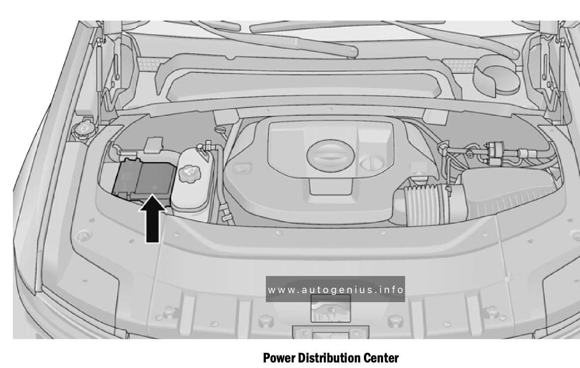
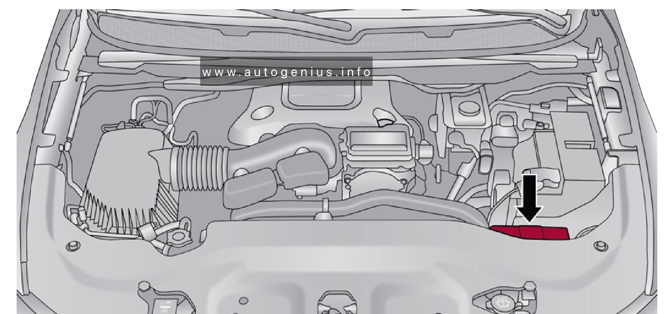
Engine compartment fuse box
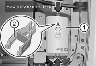
Fuse box location
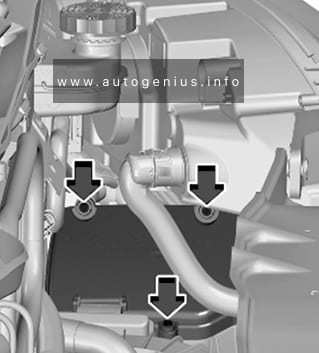
The Power Distribution Center (PDC) is located on the passenger side of the engine compartment, behind the headlamp.
Jeep Grand Cherokee (WL; 2021 – 2024) – fuse and relay box location -engine compartment
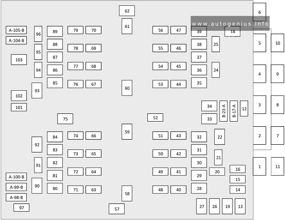
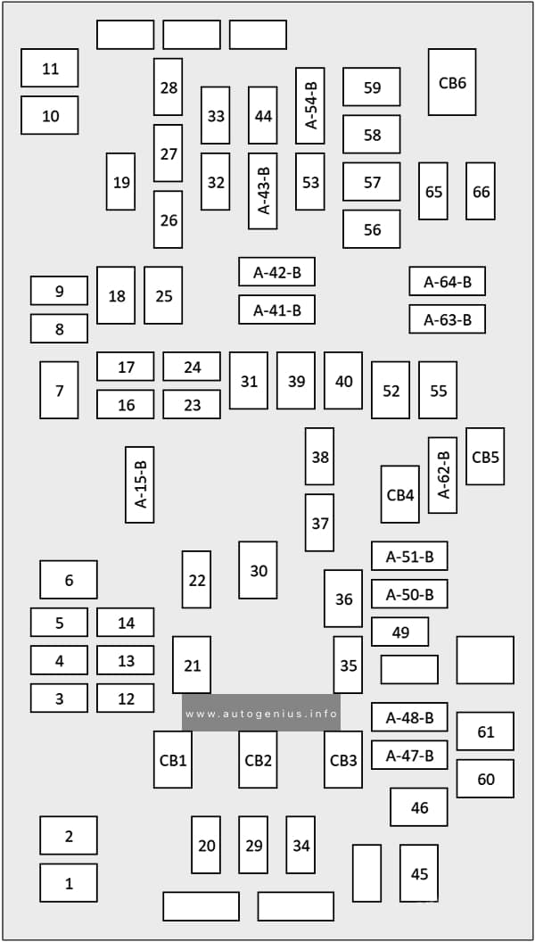
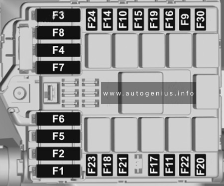
Fuse box diagram
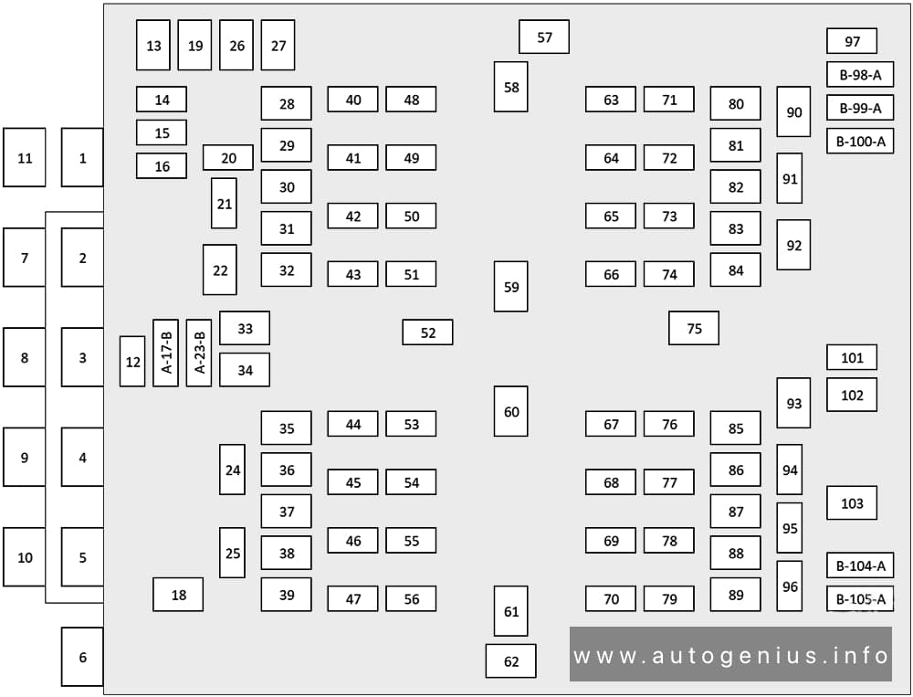
Jeep Grand Cherokee (WL; 2021 – 2024) – fuse and relay box diagram -engine compartment
Assignment of the fuses and relay in power distribution center
№
Cartridge Fuse
Micro Fuse
Description
F01
–
–
Crank Batt
F02
–
–
Spare
F03
500A Gray
–
Starter
F04
250A Gray
–
Alternator
F05
–
–
Spare
F06
–
–
Aux Battery
F07
100A Gray
–
Rad Fan
F08
80A Gray
–
Electrical Power Steering Module (EPS) #1
F09
80A Gray
–
Electrical Power Steering Module (EPS) #2
F10
80A Gray
–
Feed to IPDC
F11
150A Gray
–
PCR
F12
–
–
–
F13
40A Green
–
Starter
F14
–
10A Red
GNMM/VPMS
F15
–
10A Red
ECM
F16
–
15A Blue
Cluster
F17A
–
10A Red
EPS
F17B
–
–
–
F18
30A Pink
–
2021-2022: Headlamp Washer
F19
30A Pink
–
BSM Valves #2
F20
–
–
–
F21
–
–
–
F22
–
–
–
F23A
–
10A Red
ECM / EPS / PIM / SLM / GPF
F23B
–
10A Red
Air Suspension / ELSD RR
F24
–
–
–
F25
–
–
–
F26
50A Red
–
BSM Motor #2
F27
30A Pink
–
Rear Defroster (EBL)
F28
–
–
–
F29
–
–
–
F30
–
–
–
F31
–
–
–
F32
–
–
–
F33
–
–
–
F34
–
–
–
F35
–
–
–
F36
50A Red
–
BCM Feed #1
F37
30A Pink
–
DTCM
F38
–
–
–
F39
–
–
–
F40
–
5A Tan
Battery Sensor #1
F41
–
20A Yellow
CADM MAP
F42
–
–
–
F43
–
10A Red
Engine Control Module (ECM)
F44
–
–
–
F45
–
15A Blue
Front Axle Disconnect
F46
–
–
–
F47
–
–
–
F48
–
10A Red
CVPAM
F49
–
–
–
F50
–
–
–
F51
–
20A Yellow
Fuel Pump
F52
–
–
–
F53
–
–
–
F54
–
20A Yellow
Headlamp (left)
F55
–
15A Blue
BPCM
F56
–
–
–
F57
–
–
–
F58
–
–
–
F59
–
–
–
F60
–
–
–
F61
–
–
–
F62
–
–
–
F63
–
20A Yellow
Camera Washer Front
F64
–
15A Blue
Smart Bar Control Module (ASBS)
F65
–
15A Blue
ACT Grille Shutter / ACT Rear Axle Coolant Valve / Active Air Dam
F66
–
20A Yellow
Horns
F67
–
10A Red
DTCM / ASBS / Switchable Engine Mount / BSM #2
F68
–
20A Yellow
Headlamp (right)
F69
–
–
–
F70
–
20A Yellow
IGN Coil / IGN Capacitors / Fuel Inj
F71
–
–
–
F72
–
–
–
F73
–
–
–
F74
–
–
–
F75
–
–
–
F76
–
5A Tan
IDCM
F77
–
20A Yellow
TCM SBW
F78
–
20A Yellow
ECM
F79
–
10A Red
Fuel Door / ELCM / Fuel Injectors
F80
20A Blue
–
ECM
F81
40A Green
–
BCM Feed #4
F82
–
–
–
F83
40A Green
–
LTR Coolant Pump / Trans Oil Pump
F84
–
–
–
F85
–
10A Red
PCR
F86
50A Red
–
2021-2022: BSM Feed #1 – Valves
2023: BSM Feed #1
F87
–
–
–
F88
50A Red
–
2021-2022: BSM Feed Motor #1
2023: BSM Feed #2
F89
–
–
–
F90
–
–
–
F91
–
–
–
F92
20A Blue
–
Front De-Icer
F93
–
–
–
F94
–
10A Red
A/C Compressor Clutch
F95
–
10A Red
Batt Cool Heater
F96
–
5A Tan
Elect Cool Heater
F97
–
–
–
F98
–
–
–
F99
–
–
–
F100A
–
–
–
F100B
–
–
–
F101
–
–
–
F102
–
–
–
F103
30A Pink
–
Front Wiper
F104A
–
15A Blue
PECP Low Temp Passive Pump
F104B
–
15A Blue
AHP High Temp Aux Pump
F105A
–
15A Blue
BCP Low Temp Active Pump
F105B
–
15A Blue
LTR Coolant Pump PECP – 2
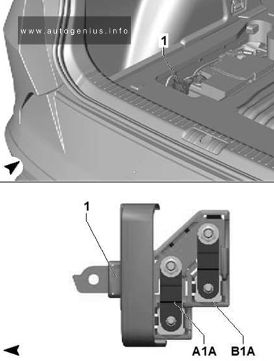
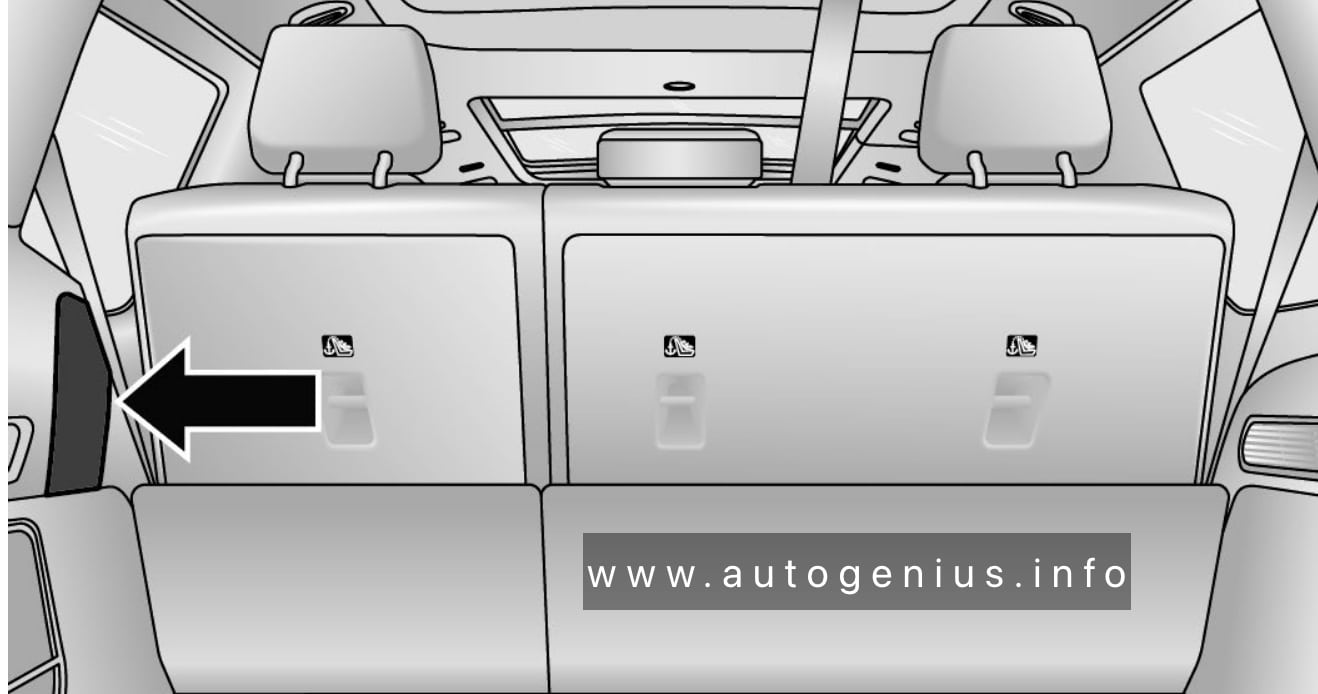
Rear Power Distribution Center
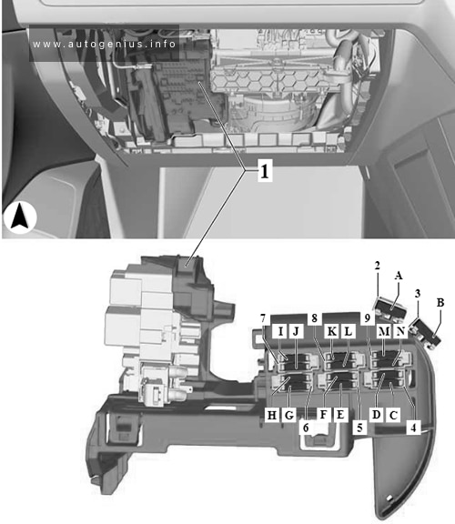
Fuse box location
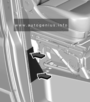
The Rear Power Distribution Center is located underneath the passenger seat.
Fuse box diagram
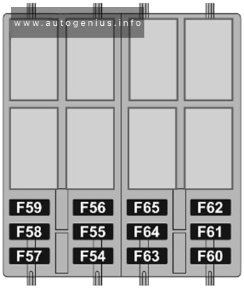
Jeep Grand Cherokee (WL; 2021 – 2024) – fuse and relay box diagram -rear compartment
Assignment of the fuses in the rear power distribution center
№
Cartridge Fuse
Micro Fuse
Description
F01
–
–
Spare
F02
–
–
Spare
F03
Shunt
–
Auxiliary Battery Feed
F04
–
–
Spare
F05
150A Gray
–
Underhood PDC Feed
F06
–
–
Spare
F07
–
–
Spare
F08
–
–
Spare
F09
–
–
Spare
F10
–
–
Spare
F11
50A Red
–
Mod BCM Feed #2
F12
–
–
Spare
F13
–
–
Spare
F14
–
–
Spare
F15A
–
–
Spare
F15B
–
10A Red
Hands-Free Liftgate/ Rear Window Switches / MOD HVAC Cntrl Frt
F16
–
–
Spare
F17
40A Green
–
Mod BCM Feed #3
F18
30A Pink
–
Power Liftgate Module
F19A
–
10A Red
L2+ Driver Alert Lighting Module
F19B
–
–
Spare
F20A
–
15A Blue
Central ADAS Decision Module (CADM)
F20B
–
15A Blue
Spare
F21A
–
–
Spare
F21B
–
–
Spare
F22
–
–
Spare
F23
–
10A Red
Media Hub #2(RR)/#3 (LR)
F24
–
–
Spare
F25
30A Pink
–
Mod Door MUX Passenger
F26
20A Blue
–
Headrest Dump 3rd Row (LT & RT)
F27
–
–
Spare
F28
30A Pink
–
MOD Memory / Power Seat (Passenger Frt)
F29A
–
10A Red
MOD ICS Switch Bank Rear (Frt Console)
F29B
–
–
Spare
F30
30A Pink
–
MOD Memory / Power Seat (Driver Frt)
F31
–
–
Spare
F32
–
–
Spare
F33
–
–
Spare
F34
30A Pink
–
MOD Door MUX Driver
F35
25A Clear
–
Trailer Tow Module #2
F36A
–
10A Red
Intelligent Event Base Lighting Module
F36B
–
10A Red
Port Pwr USB Console (USB CH Only) / Port UCI Dual USB Rear
F37
25A Clear
–
Trailer Tow Module #1
F38
–
–
Spare
F39
–
–
Spare
F40
–
30A Green
Mod Audio Amplifier #1A
F41
–
–
Spare
F42A
–
–
Spare
F42B
–
10A Red
Rear Entertainment Screens 1 (Resl) / (Res2)/ Media Hub #2 RR Wake Up / Media Hub #3 Wake Up / APO Illumination / 2nd -3rd Row Seat Switches-lllumination
F43
–
–
Spare
F44A
–
20A Yellow
12 Volt Power Outlet Cargo Area (Ign)
F44B
–
20A Yellow
12 Volt Power Outlet Cargo Area (Battery)
F45
–
20A Yellow
MOD CRSM (Heated Seat RR RT)
F46
30A Pink
–
Folding Seat Module 3rd Row Feed #1
F47
–
–
Spare
F48
–
–
Spare
F49
–
–
Spare
F50
–
15A Blue
Seat Massage Driver Mod (SSMD) / Seat Massage Passenger Mod (SSMP)
Jeep Grand Wagoneer (2022 – 2024) – fuse and relay box diagram
Year of production: 2022, 2023, 2024
This article covers the fourth-generation Jeep Wagoneer (WS), available from 2021 to the present. It includes fuse box diagrams for the 2022, 2023 and 2024 Jeep Wagoneer models, provides information on the locations of the fuse panels within the vehicle, and details the assignment of each fuse (fuse layout).
Pasenger Compartment Fuse Box
Fuse box location
The Interior Power Distribution Center is located under the driver’s instrument panel.
Jeep Grand Wagoneer – fuse and relay box location – passenger compartment
Fuse box diagram
Jeep Grand Wagoneer – fuse and relay box location – passenger compartment
Assignment of the fuses in the Interior Power Distribution Center
№
Cartridge Fuse
Micro Fuse
Description
F01
–
–
Spare
F02
–
–
Spare
F03
–
15A Blue
MOD Seat Heater Frt (Steering Wheel)
F04
–
10A Red
Night Vision Module / Driver Monitoring Camera (DMC)
This article covers the fourth-generation Jeep Wagoneer (WS), available from 2021 to the present. It includes fuse box diagrams for the 2022, 2023 and 2024 Jeep Wagoneer models, provides information on the locations of the fuse panels within the vehicle, and details the assignment of each fuse (fuse layout).
Pasenger Compartment Fuse Box
Fuse box location
The Interior Power Distribution Center is located under the driver’s instrument panel.
Ford F-150 Lightning (2022 – 2024) – fuse and relay box diagram
Year of production: 2022, 2023, 2024
The Ford F-150 Lightning, a battery-electric pickup truck, has been available from 2022 to the present. In this guide, you’ll find fuse box diagrams for the 2022, 2023 and 2024 Ford F-150 Lightning models, along with details on the locations of the fuse panels inside the vehicle and the assignment of each fuse (fuse layout).
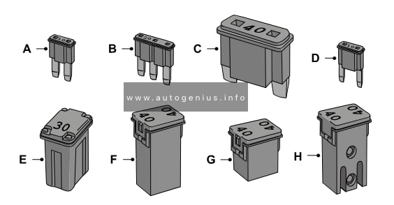
Identifying fuse type
Identifying fuse type
Micro 2
Micro 3
Maxi
Mini
M Case
J Case
J Case Low Profile
Slotted M Case
Passenger Compartment Fuse Box
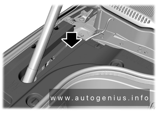
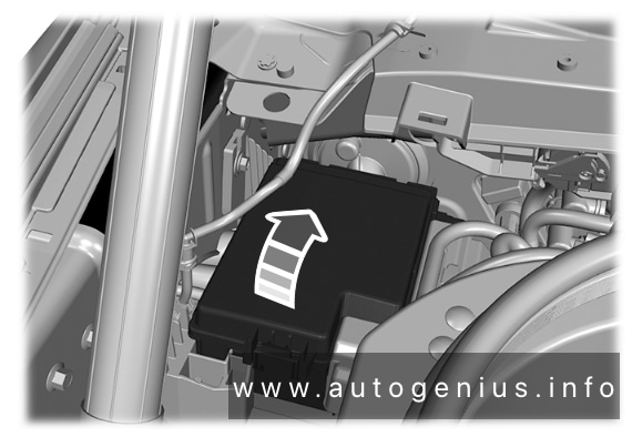
Fuse Box Location
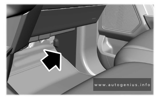
The fuse panel is in the right-hand side of the passenger footwell behind a trim panel.
Ford F-150 Lightning – fuse and relay box location – passenger compartment
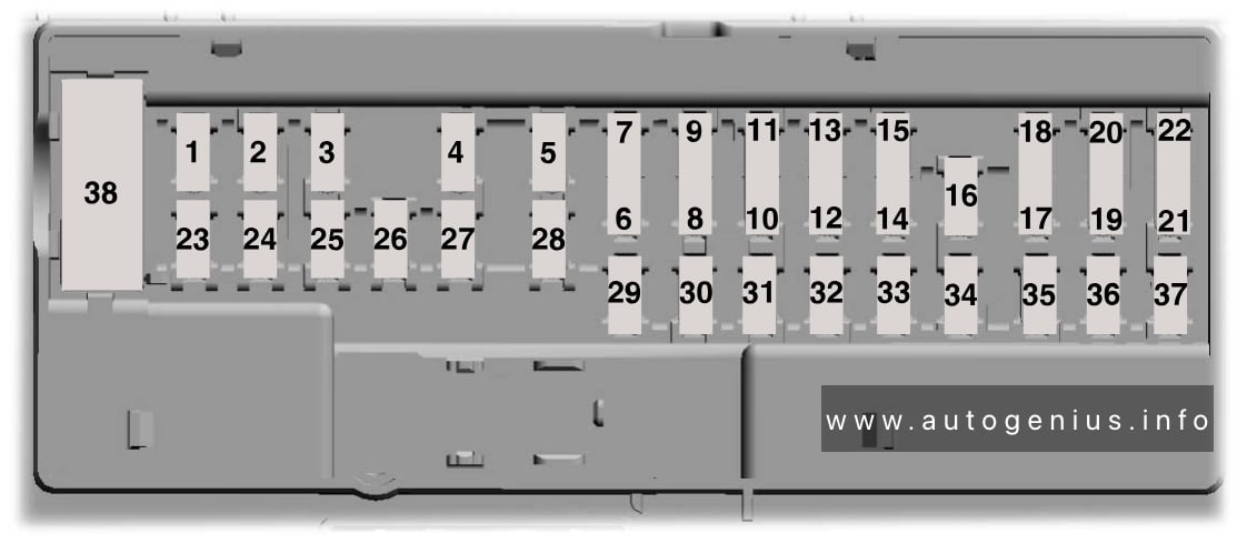
Fuse Box Diagram
Ford F-150 Lightning – fuse and relay box diagram – passenger compartment
Assignment of the fuses in the passenger compartment
Opel Vivaro C (2020 – 2023) – fuse and relay box diagram
Year of production: 2020, 2021, 2022, 2023
This article covers the third-generation Opel Vivaro C (Vauxhall Vivaro C), available from 2020 to the present. It includes fuse box diagrams for the 2020, 2021, 2022, and 2023 Opel Vivaro C models, provides information on the locations of the fuse panels within the vehicle, and details the assignment and layout of each fuse (fuse layout).
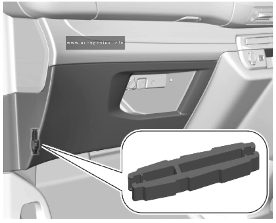
Fuse extractor
A fuse extractor may be located behind the passenger compartment fuse box cover. Unclip the cover by pulling at the top left, then right. Disengage the cover completely and turn it over.
Opel Vivaro C – fuse and relay box location – passenger compartment (fuse extractor)
The extractor has two sides, each side is designed for a different type of fuses.
Passenger Compartment Fuse Panel
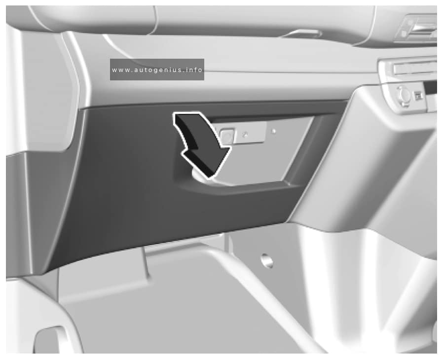
Fuse Box Location
The fuse box is located behind a cover in the instrument panel at the left side. Unclip the cover by pulling at the top left, then right. Disengage the cover completely and turn it over.
Opel Vivaro C – fuse and relay box location – passenger compartment
Fuse Box Diagram
Version 1 (Eco)
Opel Vivaro C – fuse and relay box location – passenger compartment (version 1 (eco))
Assignment of the fuses in the instrument panel (Version 1 (Eco))
№
Circuit
1
Clutch switch, power steering
4
Horn
5
Front and rear screenwash pump
6
Front and rear screenwash pump
7
Rear power outlet
8
Rear window wipers
10/11
Central locking system
13
Head-up display, climate controls, Infotainment system controls, gear selector
14
Anti-theft alarm system, telematic unit
17
Instrument cluster
19
Steering wheel controls
21
Anti-theft system or electronic key system
22
Front camera, rain and light sensor
23
Seat belt reminder
24
Parking assist, Infotainment system, rear view camera
25
Airbags
29
Infotainment system
31
Infotainment system (+ battery)
32
Front power outlet
34
Interior mirror, blind spot monitoring system, door mirror controls
35
Heated washer jets, headlight range adjustment
36
Interior lights, torch charger
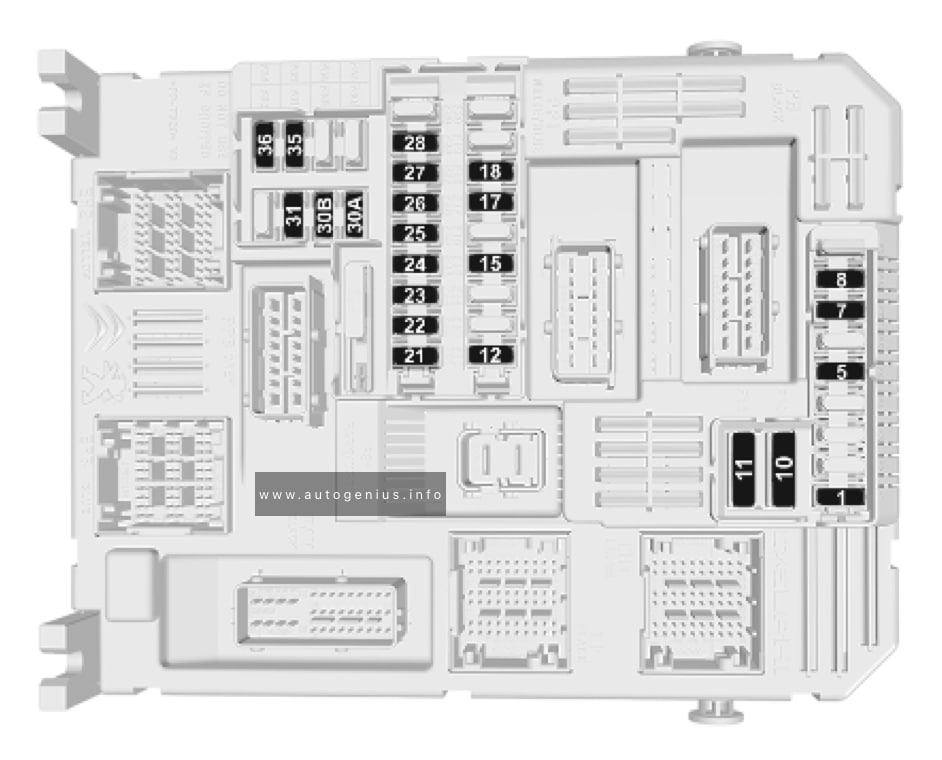
Version 2 (Full)
Opel Vivaro C – fuse and relay box location – passenger compartment (version 2 (full))
Assignment of the fuses in the instrument panel (Version 2 (Full))
№
Circuit
1
Anti-theft system or electronic key system
5
Parking assist, Infotainment system, rear view camera
7
Rear climate controls, audio system amplifier
8
Rear window wipers
10/11
Central locking system
12
Anti-theft alarm system
17
Rear power outlet
18
Telematic unit
21
Interior lights, torch charger
22
Interior lights, glovebox light
23
Blind spot monitoring system, door mirror controls
24
Steering wheel controls
25
Headlight range adjustment
26
Seat belt reminder
27
Front camera, rain and light sensor
28
Head-up display, front climate controls, Infotainment system controls, gear selector
30A or 30B
Audio system (+ battery)
31
Airbag
33
Front power outlet
35
Instrument cluster
36
Infotainment system
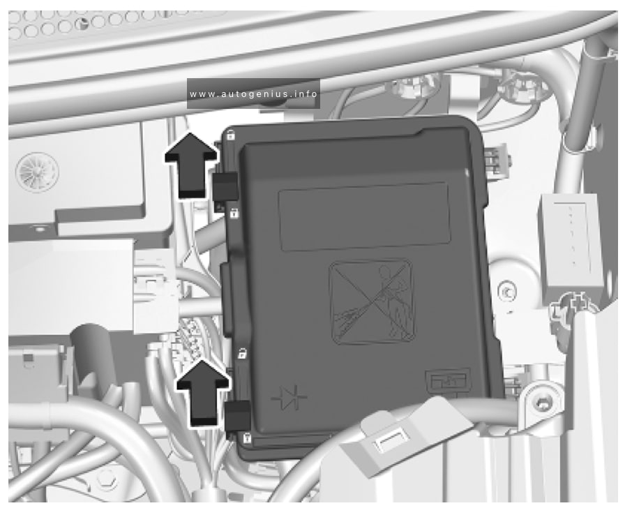
Engine Compartment Fuse Box
Fuse Box Location
The fuse box is in the front left of the engine compartment. Disengage the cover and remove it.
Opel Vivaro C – fuse and relay box location – engine compartment
Assignment of the fuses in the engine compartment
№
Circuit
12
Heated washer jets
14
Front and rear screenwash pump
15
Front radar system, electric power steering
17
Built-in systems interface
19
Front wiper motor
20
Front and rear screenwash pump
21
Headlight wash pump
22
Horn
23
Right high beam
24
Left high beam
WARNING: Terminal and harness assignments for individual connectors will vary depending on vehicle equipment level, model, and market.
Vauxhall Vivaro C (2020 – 2023) – fuse and relay box diagram
Year of production: 2020, 2021, 2022, 2023
This article covers the third-generation Opel Vivaro C (Vauxhall Vivaro C), available from 2020 to the present. It includes fuse box diagrams for the 2020, 2021, 2022, and 2023 Opel Vivaro C models, provides information on the locations of the fuse panels within the vehicle, and details the assignment and layout of each fuse (fuse layout).
Fuse extractor
A fuse extractor may be located behind the passenger compartment fuse box cover. Unclip the cover by pulling at the top left, then right. Disengage the cover completely and turn it over.
Vauxhall Vivaro C – fuse and relay box location – passenger compartment (fuse extractor)
The extractor has two sides, each side is designed for a different type of fuses.
Passenger Compartment Fuse Panel
Fuse Box Location
The fuse box is located behind a cover in the instrument panel at the left side. Unclip the cover by pulling at the top left, then right. Disengage the cover completely and turn it over.
Vauxhall Vivaro C – fuse and relay box location – passenger compartment
Fuse Box Diagram
Version 1 (Eco)
Vauxhall Vivaro C – fuse and relay box location – passenger compartment (version 1 (eco))
Assignment of the fuses in the instrument panel (Version 1 (Eco))
№
Circuit
1
Clutch switch, power steering
4
Horn
5
Front and rear screenwash pump
6
Front and rear screenwash pump
7
Rear power outlet
8
Rear window wipers
10/11
Central locking system
13
Head-up display, climate controls, Infotainment system controls, gear selector
14
Anti-theft alarm system, telematic unit
17
Instrument cluster
19
Steering wheel controls
21
Anti-theft system or electronic key system
22
Front camera, rain and light sensor
23
Seat belt reminder
24
Parking assist, Infotainment system, rear view camera
25
Airbags
29
Infotainment system
31
Infotainment system (+ battery)
32
Front power outlet
34
Interior mirror, blind spot monitoring system, door mirror controls
35
Heated washer jets, headlight range adjustment
36
Interior lights, torch charger
Version 2 (Full)
Vauxhall Vivaro C – fuse and relay box location – passenger compartment (version 2 (full))
Assignment of the fuses in the instrument panel (Version 2 (Full))
№
Circuit
1
Anti-theft system or electronic key system
5
Parking assist, Infotainment system, rear view camera
7
Rear climate controls, audio system amplifier
8
Rear window wipers
10/11
Central locking system
12
Anti-theft alarm system
17
Rear power outlet
18
Telematic unit
21
Interior lights, torch charger
22
Interior lights, glovebox light
23
Blind spot monitoring system, door mirror controls
24
Steering wheel controls
25
Headlight range adjustment
26
Seat belt reminder
27
Front camera, rain and light sensor
28
Head-up display, front climate controls, Infotainment system controls, gear selector
30A or 30B
Audio system (+ battery)
31
Airbag
33
Front power outlet
35
Instrument cluster
36
Infotainment system
Engine Compartment Fuse Box
Fuse Box Location
The fuse box is in the front left of the engine compartment. Disengage the cover and remove it.
Vauxhall Vivaro C – fuse and relay box location – engine compartment
Assignment of the fuses in the engine compartment
№
Circuit
12
Heated washer jets
14
Front and rear screenwash pump
15
Front radar system, electric power steering
17
Built-in systems interface
19
Front wiper motor
20
Front and rear screenwash pump
21
Headlight wash pump
22
Horn
23
Right high beam
24
Left high beam
WARNING: Terminal and harness assignments for individual connectors will vary depending on vehicle equipment level, model, and market.
Vauxhall Movano C (2021 – 2023) – fuse and relay box diagram
Year of production: 2021, 2022, 2023
This article focuses on the third-generation Opel Movano (Vauxhall Movano), available from 2021 to the present. It includes fuse box diagrams for the 2021, 2022, and 2023 Opel Movano C models, provides details on the locations of the fuse panels within the vehicle, and explains the function and layout of each fuse (fuse layout).
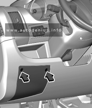
Passenger Compartment Fuse Panel
Fuse Box Location
The fuse box is located behind a cover in the instrument panel at the left side. Remove the screws with the screwdriver and remove the cover to access the fuses.
Vauxhall Movano C – fuse and relay box location – passenger compartment
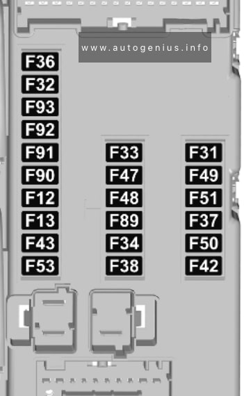
Fuse Box Diagram
Vauxhall Movano C – fuse and relay box diagram – passenger compartment
Assignment of the fuses in the instrument panel
№
Circuit
12
Right low beam
13
Left low beam
31
Instrument panel control unit
32
Interior lights
33
Stop-start system
34
Interior lights
Minibus – Hazard warning flashers
36
Infotainment system / Climate control / Alarm / Tachograph / Battery disconnecting control unit / Additional heater / Tyre pressure monitoring / Stop-start system
37
Brake system / Instrument panel
38
Central locking system
42
Electronic stability control system / Traction control system / ABS / Brake lights
43
Windscreen washer
47
Electric windows
48
Electric windows
49
Parking assist / Infotainment system / Steering wheels controls / Central and side control panels / Auxiliary control panel / Battery disconnecting control unit / Trailer hitch / Rain sensor / Stop-start system
50
Airbag system / Pretensioners
51
Tachograph / Power steering / Climate control system / Reversing lights / Navigation system / Lane departure warning / Rear view camera / Headlights
53
Insrument panel
89
–
90
Left high beam
91
Right high beam
92
Left front fog light
93
Right front fog light
Additional Fuse Box
Fuse Box Location
There is a fuse box located in the right B-pillar.