Lincoln Corsair (2020 – 2022) – fuse and relay box diagram
Year of production: 2020, 2021, 2022
The Lincoln Corsair, a compact premium crossover, has been in production since 2020. In this article, you’ll find fuse box diagrams for the 2020, 2021 and 2022 Lincoln Corsair, details on where the fuse panels are located within the vehicle, and information on the function of each fuse (fuse layout).
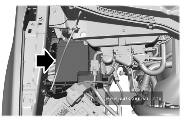
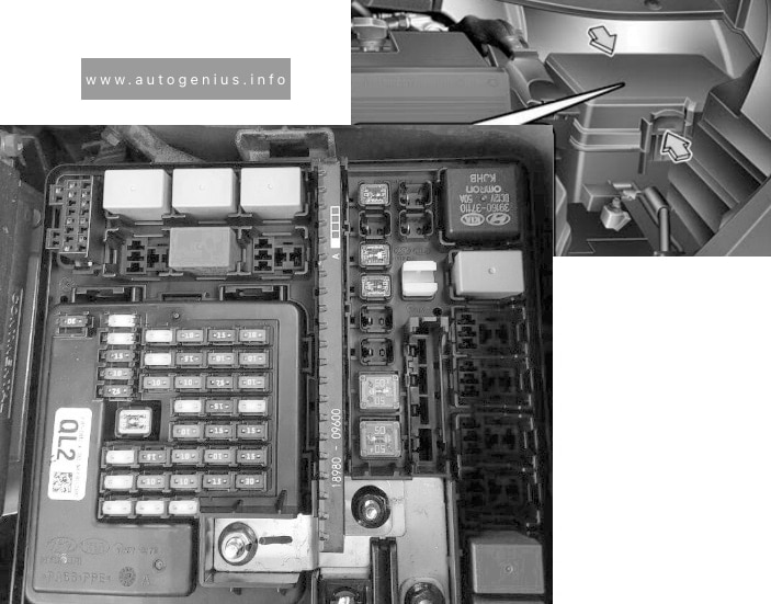
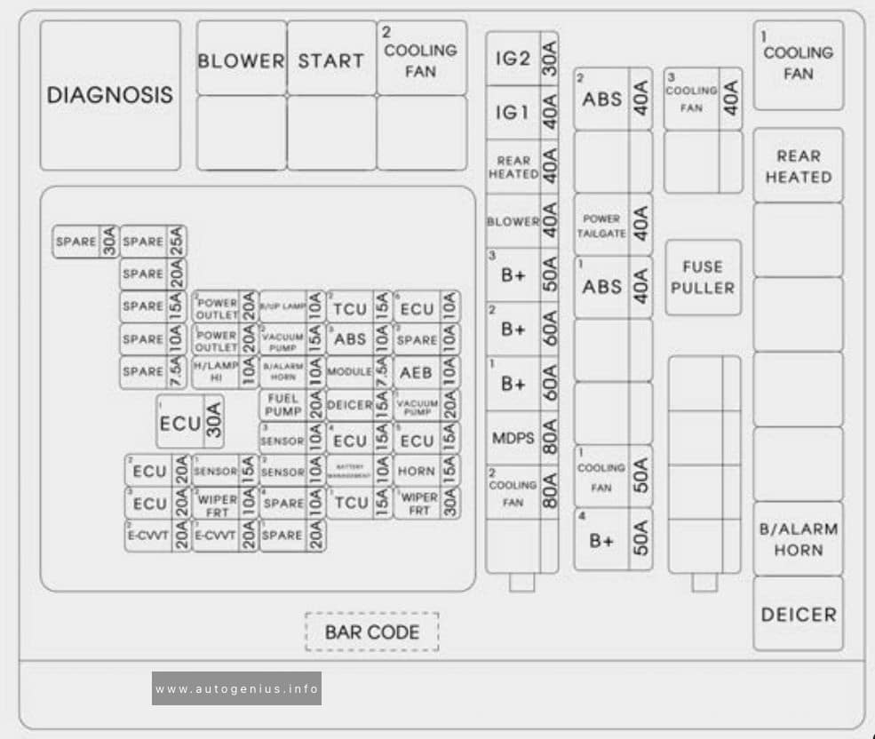
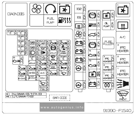
Engine compartment fuse box
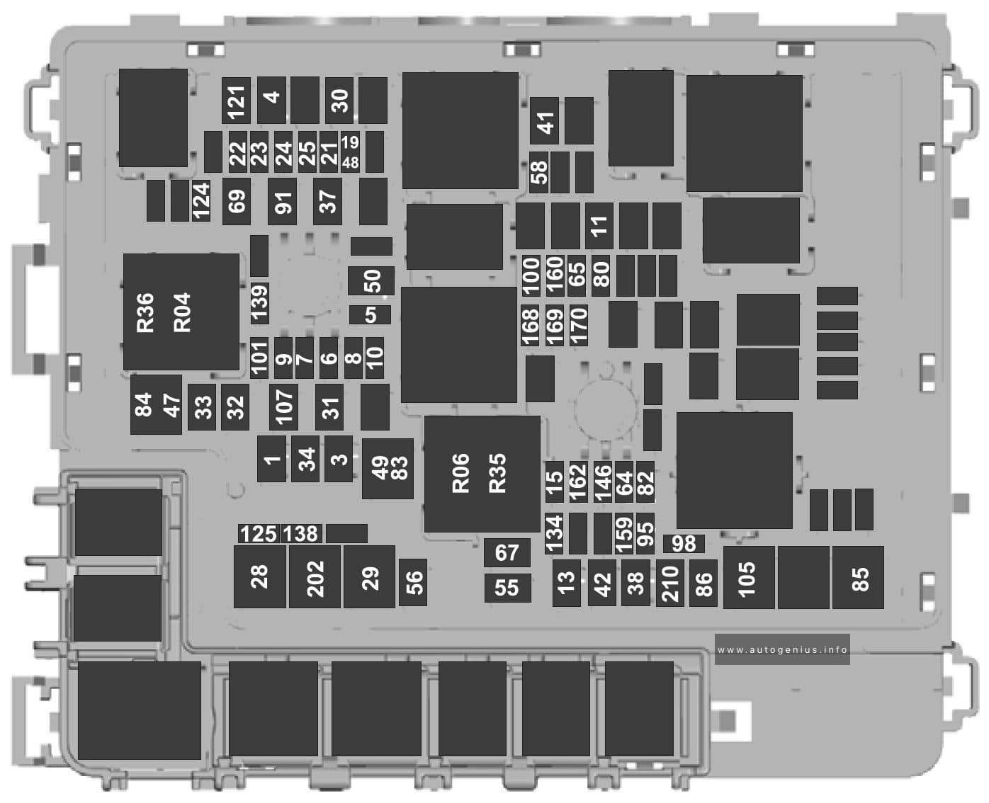
Fuse box diagram
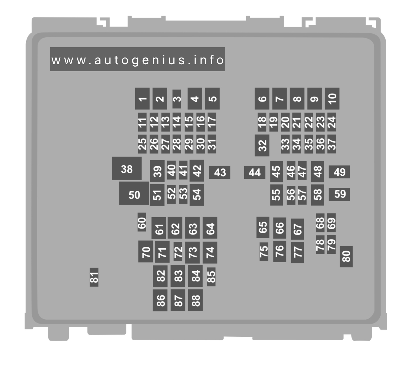
Assignment of the fuses in the engine compartment (2020 – 2022)
| No. | A | Description |
|---|---|---|
| 1 | — | — |
| 2 | 30 | Heated backlight |
| 3 | 10 | ’20: Heated exterior mirrors |
| 4 | 50 | Hybrid: Electric water pump |
| 5 | — | — |
| 6 | — | — |
| 7 | 40 | Driveline control module |
| 8 | — | — |
| 9 | 30 | Second row seat release |
| 10 | — | — |
| 11 | 15 | Powertrain control module |
| 12 | 15 | Powertrain control module |
| 13 | 15 | Powertrain control module |
| 14 | 15 | Powertrain control module |
| 15 | — | — |
| 16 | — | — |
| 17 | 15 | Heated wiper park |
| 18 | 10 | Air conditioning clutch |
| 19 | — | — |
| 20 | 5 | Hybrid: DC/DC converter |
| 21 | 10 | Hybrid: Battery charge control module |
| 22 | 5 | ’20: Adaptive cruise control |
| 23 | 5 | Hybrid: Charge port light ring |
| 24 | 5 | Hybrid: Battery electronic control module |
| 25 | 25 | Left-hand enhanced exterior lighting module |
| 26 | 25 | Right-hand enhanced exterior lighting module |
| 27 | 5 | Hybrid: Powertrain control module |
| 28 | 10 | Anti-lock brake system module |
| 29 | 10 | Powertrain control module |
| 30 | 10 | Electronic stability control, Transmission oil pump |
| 31 | 5 | Electronic power assist steering |
| 32 | 30 | Body control module |
| 33 | 10 | Front parking aid camera, Rear view camera, Blind spot information system, Gear shift actuator (’20), Cruise control module, Image processing module B |
| 34 | 10 | Headlamp leveling |
| 35 | 15 | Heated steering wheel |
| 36 | 10 | Hybrid: Powertrain control module |
| 37 | 20 | Horn |
| 38 | 40 | Blower motor |
| 39 | — | — |
| 40 | 10 | Brake on-off switch |
| 41 | 20 | Amplifier |
| 42 | 30 | Driver power seat |
| 43 | 40 | Anti-lock brake control valves |
| 44 | 40 | ’20: Trailer tow module |
| 45 | 30 | Passenger power seat |
| 46 | 20 | ’20: Transmission oil pump, Transmission oil temperature |
| 47 | 20 | Heated seats |
| 48 | 30 | Power liftgate |
| 49 | 60 | Anti-lock brake control pump |
| 50 | 60 | Cooling fan |
| 51 | 30 | Moonroof. |
| 52 | 5 | USB charge port – rear console |
| 53 | 5 | USB charge port – rear console |
| 54 | 20 | Rear heated seat module |
| 55 | 30 | Starter motor |
| 56 | 20 | Amplifier |
| 57 | 10 | Data link connector |
| 58 | 30 | Climate controlled seat module |
| 59 | 40 | Body control module |
| 60 | — | — |
| 61 | — | — |
| 62 | — | — |
| 63 | — | — |
| 64 | — | — |
| 65 | — | — |
| 66 | — | — |
| 67 | — | — |
| 68 | 5 | ’20: Mass air flow and intake air temperature sensor |
| 69 | 15 | Port fuel injectors |
| 70 | 20 | Rear cargo power point |
| 71 | 20 | Rear console power point |
| 72 | 20 | Rear window wiper |
| 73 | — | — |
| 74 | 30 | Windshield wiper motor |
| 75 | 20 | ’20: Steering column lock |
| 76 | — | — |
| 77 | — | — |
| 78 | 15 | Multi-contour seats |
| 79 | 10 | ’20: Headlamp washer |
| 80 | 20 | Fuel pump |
| 81 | 10 | Rear window washer pump |
| 82 | 40 | ’20: Power inverter |
| 83 | — | — |
| 84 | 40 | Hybrid: Auxiliary power distribution box |
| 85 | 5 | Rain sensor |
| 86 | — | — |
| 87 | — | — |
| 88 | — | — |
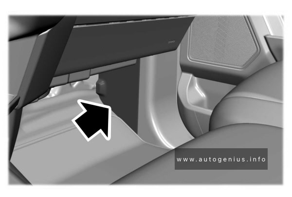
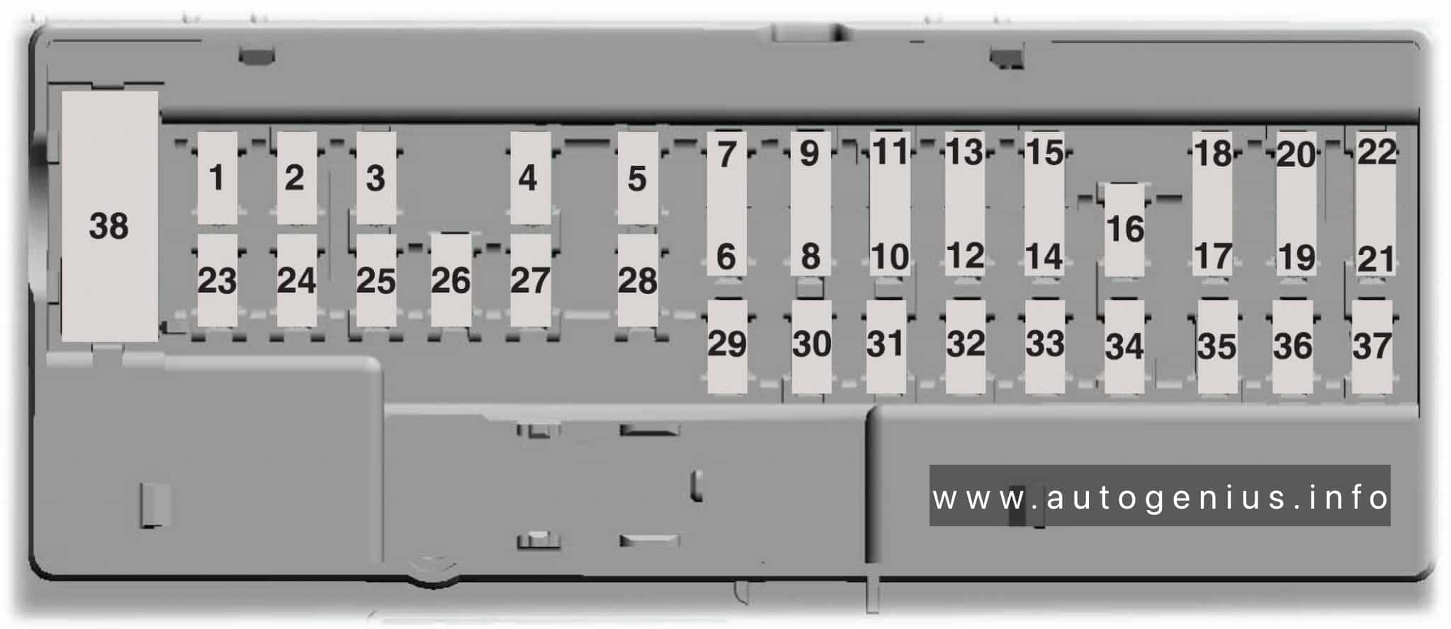
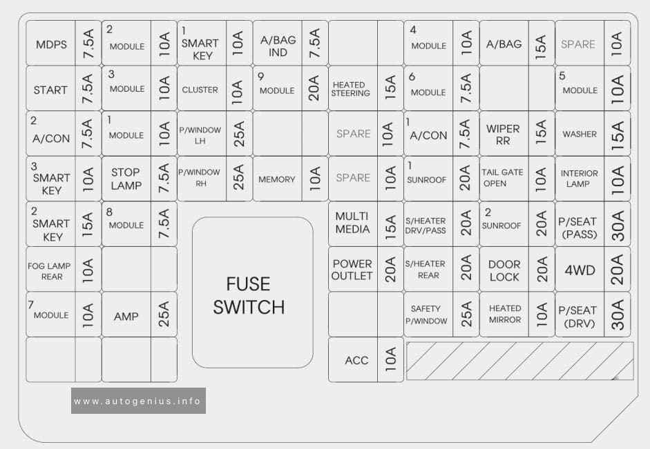
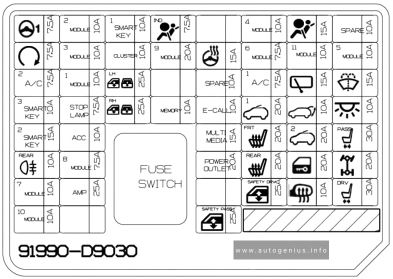
Passenger compartment fuse box
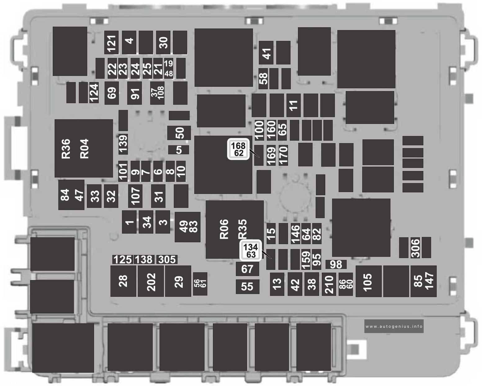
Fuse box diagram
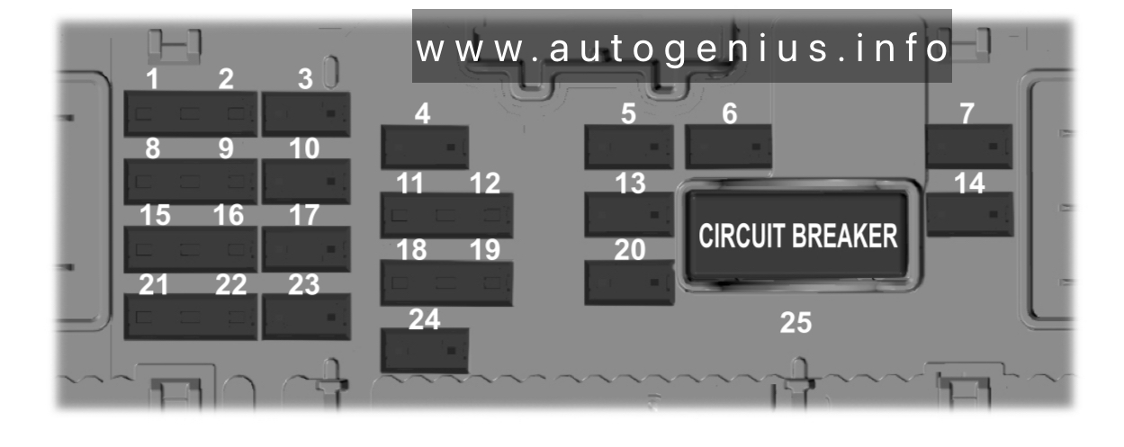
Assignment of the fuses in the passenger compartment (2020-2022)
| No. | A | Description |
|---|---|---|
| 1 | 5 | — |
| 2 | 5 | Rear heated seats |
| 3 | 10 | ’20: Pedestrian sounder |
| 4 | 10 | Ignition switch |
| 5 | 20 | Lock/Unlock |
| 6 | 10 | Moonroof, DC inverter (’20) |
| 7 | 30 | Passenger door module |
| 8 | 5 | Parking assist control module |
| 9 | 5 | Electrochromatic mirror, Image processing module A |
| 10 | 10 | Extended power module |
| 11 | 5 | Power liftgate, Hands-free liftgate actuation module, Telematics control unit module |
| 12 | 5 | Keyless keypad switch |
| 13 | 15 | Driver door lock |
| 14 | 30 | Driver door module |
| 15 | 15 | Extended power module |
| 16 | 15 | Vehicle dynamics module |
| 17 | 15 | SYNC, Receiver transceiver module, Integrated control panel |
| 18 | 7.5 | Driver power seat switch, Passenger power seat switch, Wireless accessory charging module, Selectable drive mode switch |
| 19 | 7.5 | Headlamp switch pack, Telematics control unit module, Bluetooth low energy module |
| 20 | 10 | — |
| 21 | 7.5 | Climate control, E-shifter module |
| 22 | 7.5 | Instrument cluster, Gateway module, Steering column control module |
| 23 | 20 | Audio unit |
| 24 | 20 | Head up display |
WARNING: Terminal and harness assignments for individual connectors will vary depending on vehicle equipment level, model, and market.