Dodge Hornet (2023 – 2024) – fuse box diagram
Year of production: 2023, 2024
The Dodge Hornet compact crossover has been available since 2022. In this article, you’ll find fuse box diagrams for the 2023 and 2024 Dodge Hornet models, along with details on the location of the fuse panels within the vehicle and the function of each fuse and relay (fuse layout).
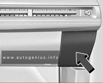
Passenger compartment Fuse Box
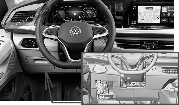
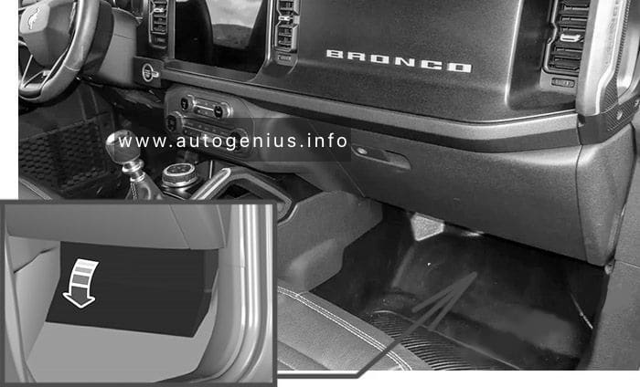
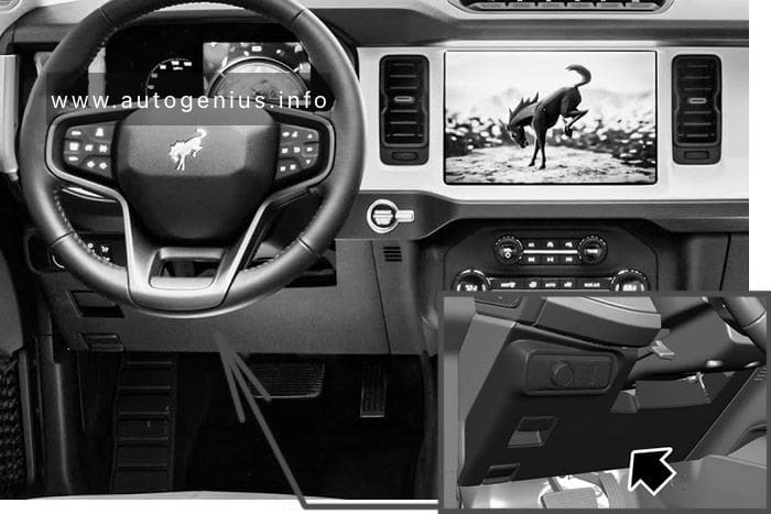
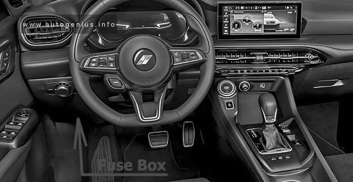
Fuse Box Location
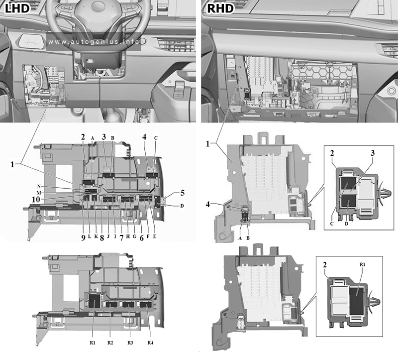
The interior fuse panel is located under the driver’s side lower instrument panel.
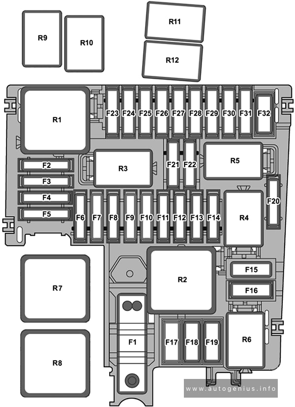
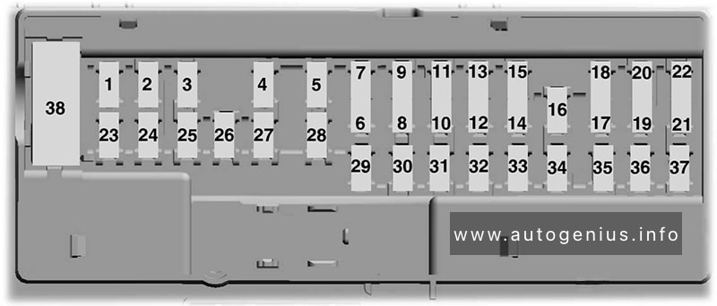
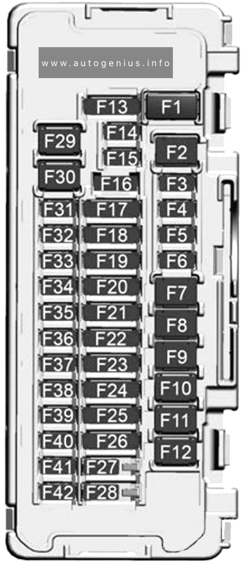
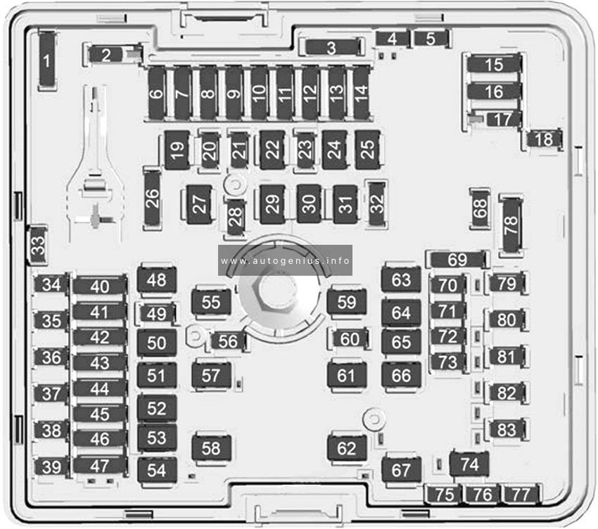
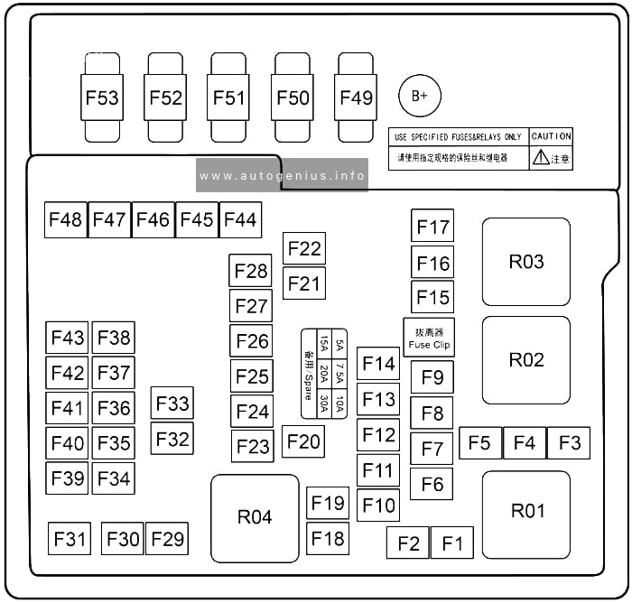
Fuse Box Diagram
Assignment of the fuses in the instrument panel
| № | Amps | Description |
|---|---|---|
| F31 | 7.5A Brown | HVAC Relay Coil & Power Outlet / Seat Relay Coil |
| F33 | 20A Yellow | Front Passenger Window Lifter |
| F34 | 20A Yellow | Front Driver Window Lifter |
| F36 | 15A Blue | HVAC / VTA / External Mirror / Ceiling Light / CVPM / Radio Mod / USB / AUX / DCSD / Electric Steering Lock |
| F37 | 10A Red | Brake Switch / DASM / IPC |
| F38 | 20A Yellow | Door Lock & Unlock / Liftgate Release |
| F42 | 7.5A Brown | Brake System Module, Electric Power Steering |
| F43 | 20A Yellow | Bi-Directional Washer Pump |
| F47 | 20A Yellow | Rear Left Window Lifter |
| F48 | 20A Yellow | Rear Right Window Lifter |
| F49 | 7.5A Brown | Park Assist, Blind Spot, Voltage Stabilizer, Humidity Sensor, Electronic Steering Lock, Temp Sense, Mirror, Heated Seats, Light And Rain Sensor, Start Stop Switch |
| F50 | 7.5A Brown | Occupant Restraint Controller |
| F51 | 7.5A Brown | Electronic Climate Control, Occupant Classification, RearView Camera, Climate Control, Headlamp Leveling, Terrain Select, Heated Rear Window, Trailer Tow, Haptic Lane Mod |
| F53 | 7.5A Brown | HCP / Reverse Gear / ISNSR / A/C Compressor / HVAC / Defrosting / Right & Left Headlamp Leveling / LDW / Alarm Mod / Psg Airbag / Trailer Tow Mod / AFLM / Air Quality Sensor / ASBM |
| F94 | 15A Blue | Power Outlet |
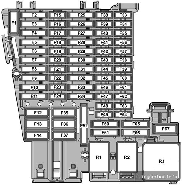
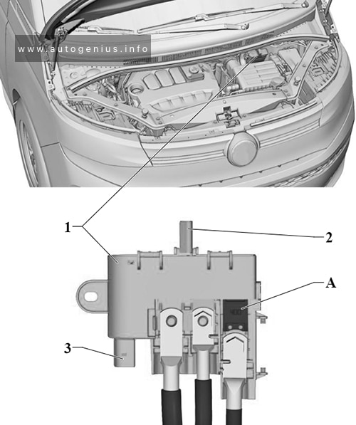
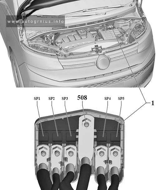
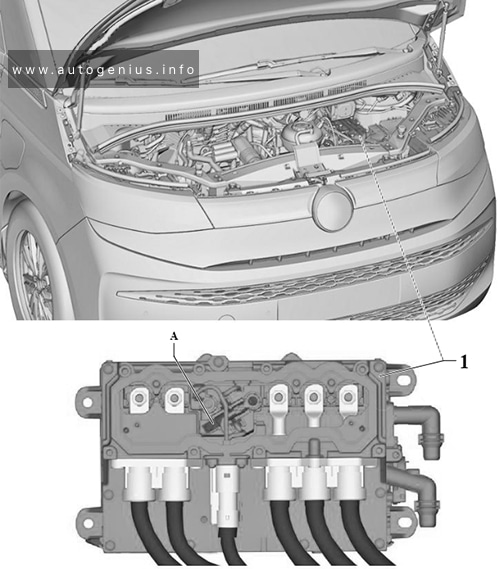
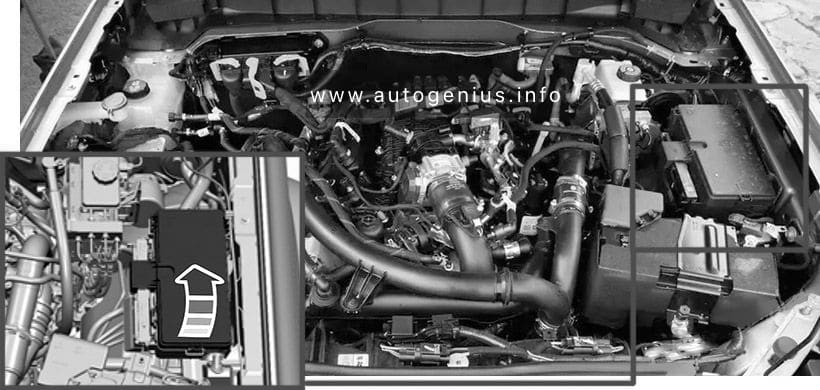
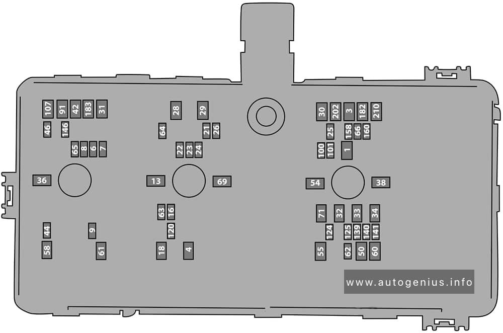
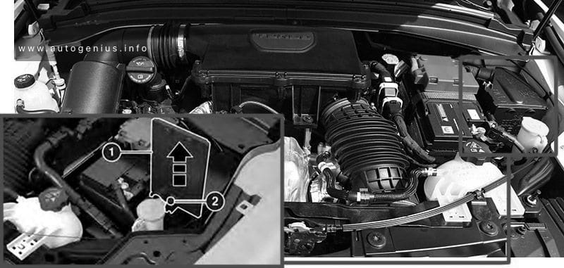
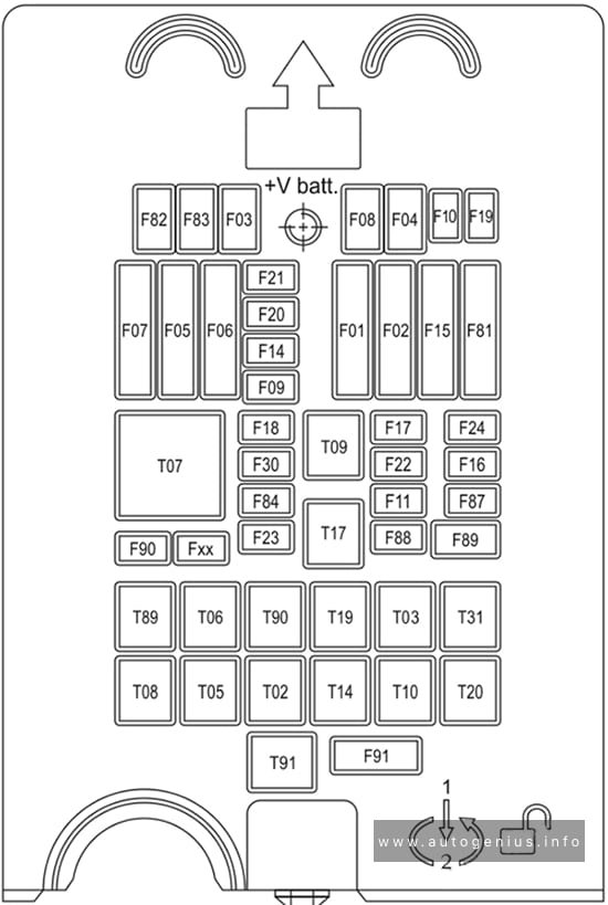
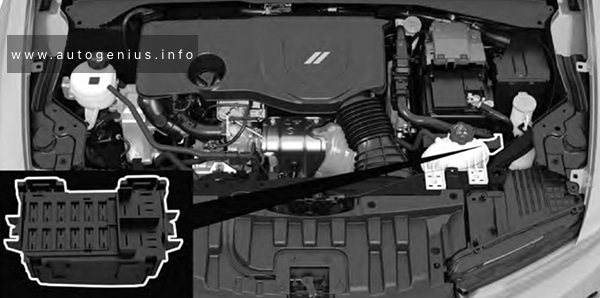
Engine Compartment Fuse Box
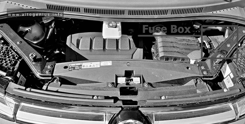
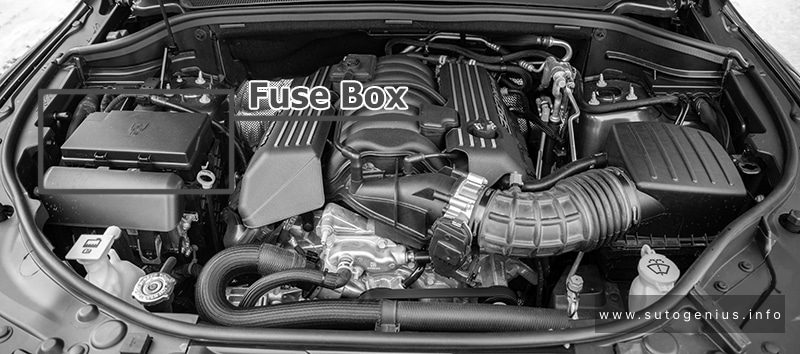
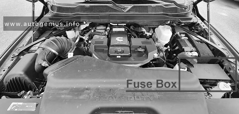
Fuse Box Location
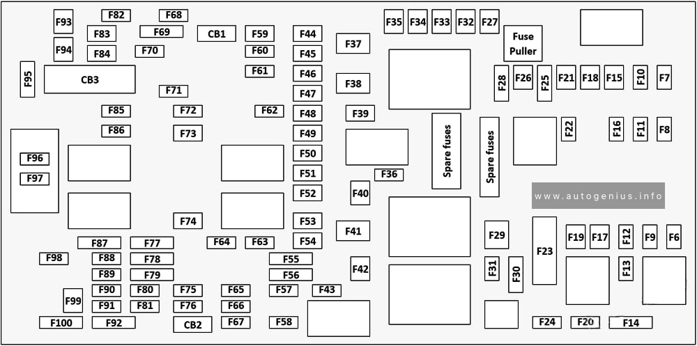
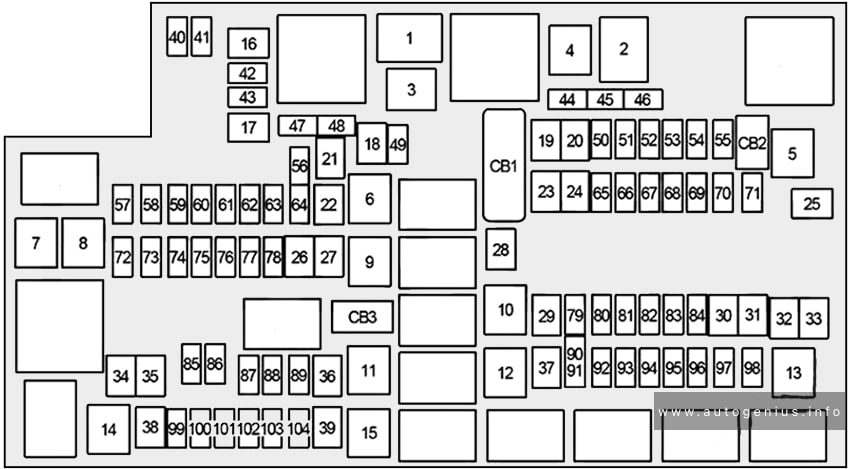
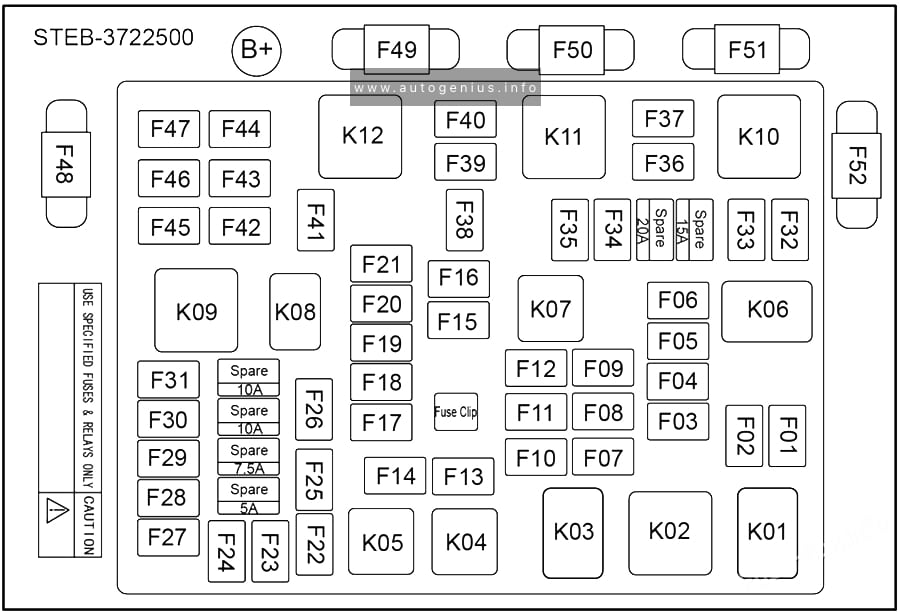
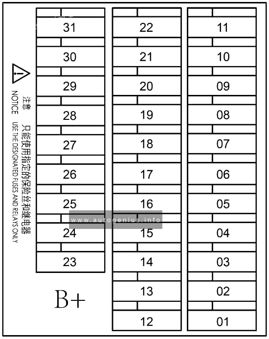
Fuse Box Diagrams
Gasoline Engine

Assignment of the fuses in the engine compartment (Gas)
| № | Amps | Description |
|---|---|---|
| F01 | 70A Tan | BCM1 |
| F02 | 70A Tan | BCM2 / RDU |
| F03 | 20A Blue | BCM3 |
| F04 | 40A Green | BCM Valves |
| F05 | 40A Orange | PTC 1 |
| F06 | 20A Yellow | Front Wiper Motor |
| F07 | 20A Yellow | DTCM |
| F08 | 30A Pink | Power Supply F24 – F87 – Fxx |
| F09 | 7.5A Brown | ECM T09 |
| F10 | 15A Blue | Horn |
| F11 | 5A Tan | Engine Secondary Loads |
| F14 | 7.5A Brown | LTR |
| F15 | 40A Orange | BSM Pump |
| F16 | 10A Red | ECM / TCM / AGSM |
| F17 | 10A Red | Engine Primary Loads |
| F18 | 5A Tan | IGNM |
| F19 | 7.5A Brown | A/C Compressor |
| F20 | 15A Blue | Rear Cargo Outlet |
| F21 | 20A Yellow | Fuel Pump |
| F22 | 15A Blue | ECM |
| F23 | 5A Tan | USB / Aux Outlet |
| F24 | 10A Red | DTCM |
| F30 | 5A Tan | AWD DTCM |
| F81 | 30A Green | Brake Booster Vacuum Pump |
| F82 | 40A Green | 2024: External Oil Pump (if equipped) |
| F83 | 40A Green | HVAC Fan |
| F84 | 7.5A Brown | Rad Fan Enable |
| F87 | 5A Tan | AGSM |
| F88 | 7.5A Brown | Heated Mirrors & Washer Nozzle |
| F89 | 30A Pink | Rear Window Defrost |
| F90 | 5A Tan | Intelligent Battery Sensor |
| T02 | – | Not Used |
| T03 | 30A | Horn Relay |
| T05 | 30A | A/C Compressor Relay |
| T06 | 30A | Rad Fan Enable Relay |
| T07 | 50A | Aux.1 / DTCM Relay |
| T08 | 30A | HVAC Fan Relay |
| T09 | 30A | Engine Main Relay |
| T10 | – | Not Used |
| T14 | 30A | Rear Cargo Power Outlet Relay |
| T17 | 30A | Rear Window Defrost / Heated Mirrors Relay |
| T19 | – | Not Used |
| T20 | 30A | Starter Relay R1 |
| T31 | 30A | Fuel Pump Relay |
| T89 | – | Not Used |
| T90 | 30A | Brake Booster Vacuum Pump Relay |
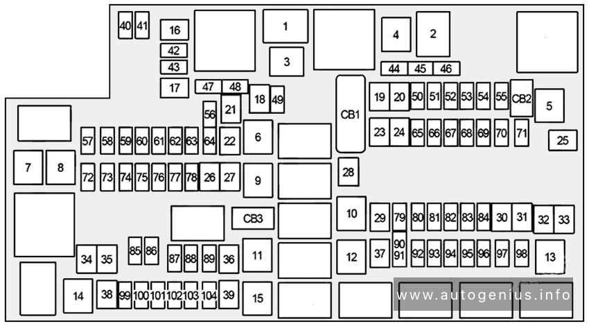
Hybrid
Assignment of the fuses in the engine compartment (Hybrid)
| № | Amps | Description |
|---|---|---|
| F01 | 70A Tan | BCM1 |
| F02 | 70A Tan | BCM2 / RDU |
| F03 | 20A Blue | BMC3 |
| F04 | 40A Green | BCM Valves |
| F05 | 40A Orange | PTC 1 |
| F06 | 20A Yellow | Front Wiper Motor |
| F07 | 50A Red | AUX 1 RDU |
| F08 | 30A Pink | Power Supply F24 – F87 – Fxx |
| F09 | 7.5A Brown | ECM T09 |
| F10 | 15A Blue | Horn |
| F11 | 5A Tan | Engine Secondary Loads |
| F14 | 7.5A Brown | LTR |
| F15 | 70A Tan | BSM Pump |
| F16 | 10A Red | ECM / TCM / AGSM |
| F17 | 10A Red | Engine Primary Loads |
| F18 | 5A Tan | IGNM (if equipped) |
| F19 | 7.5A Brown | A/C Compressor |
| F20 | 15A Blue | Rear Cargo Outlet |
| F21 | 20A Yellow | Fuel Pump |
| F22 | 20A Yellow | Engine Primary Loads |
| F23 | 5A Tan | USB / Aux Outlet |
| F24 | 10A Red | TCM |
| F30 | – | Spare |
| F81 | 40A Orange | AUX 2 RDU |
| F82 | 40A Green | External Oil Pump (AT) (if equipped) |
| F83 | 40A Green | HVAC Fan |
| F84 | 7.5A Brown | Rad Fan Enable |
| F87 | 5A Tan | AGSM |
| F88 | 7.5A Brown | Heated Mirrors & Washer Nozzle |
| F89 | 30A Pink | Rear Window Defrost |
| F90 | 5A Tan | Intelligent Battery Sensor |
| Fxx | 25A Clear | PIM |
| T02 | – | Not Used |
| T03 | 30A | Horn Relay |
| T05 | 30A | A/C Compressor Relay |
| T06 | 30A | Rad Fan Enable Relay |
| T07 | 50A | Aux.1 Relay |
| T08 | 30A | HVAC Fan Relay |
| T09 | 30A | Engine Main Relay |
| T10 | – | Not Used |
| T14 | 30A | Rear Cargo Power Outlet Relay |
| T17 | 30A | Rear Window Defrost / Heated Mirrors Relay |
| T19 | 30A | External Oil Pump Relay |
| T20 | 30A | Starter Relay R1 |
| T31 | 30A | Fuel Pump Relay |
| T89 | – | Not Used |
| T90 | 30A | Brake Booster Vacuum Pump Relay |
Supplemental Fuse Box (Hybrid)
| № | Amps | Description |
|---|---|---|
| F01 | 5A Tan | Electric Air Heater (EAH) |
| F02 | 7.5A Brown | Electric Air Compressor (EAC) |
| F03 | 5A Tan | Integrated Dual Charge Module (IDCM) |
| F04 | 5A Tan | Charge Port Indicator Module (CPIM) |
| F05 | 15A Blue | Power Electronic Coolant Pump 2 (PECP2) |
| F06 | 15A Blue | Power Electronic Coolant Pump (PECP) |
| F07 | 5A Tan | Aux Heater Pump (AHP) |
| F08 | 5A Tan | PIM Feed 1 |
| F09 | 10A Red | BPCM Feed 1 |
| F10 | 5A Tan | PIM Feed 3 |
| F11 | 10A Red | BPCM Feed 2 |
| F12 | 5A Tan | Electronic Pedestrian Protection Module (EPPM) |
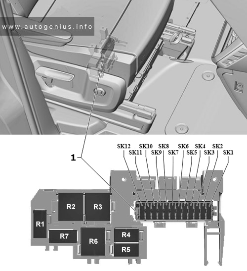
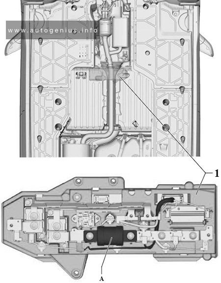
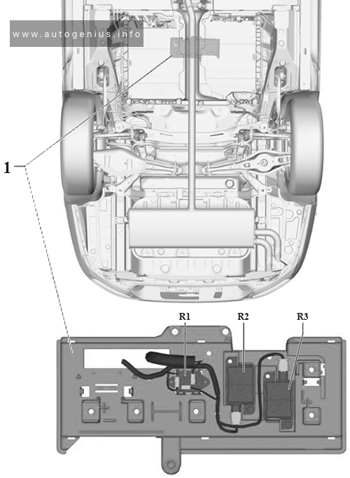
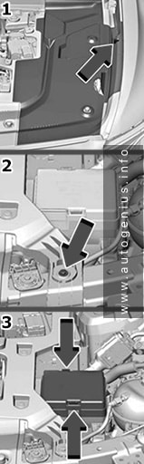
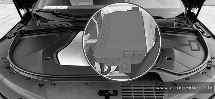
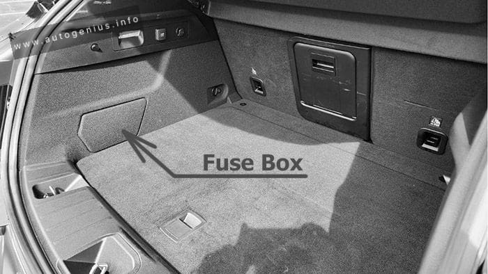
Cargo Compartment Fuse Box
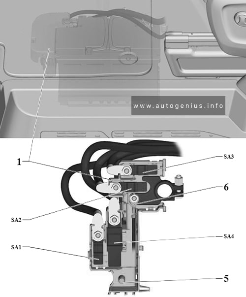
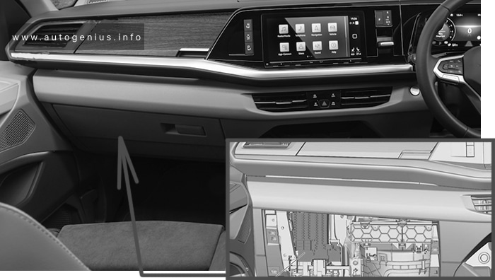
Fuse Box Location
To access the fuses, remove the access panel from the left rear section of the cargo area. The fuses may be housed in two separate units. Fuse Holder №1 is positioned nearest to the rear of the vehicle, while Fuse Holder №2 (if equipped with trailer towing) is located closer to the front of the vehicle.
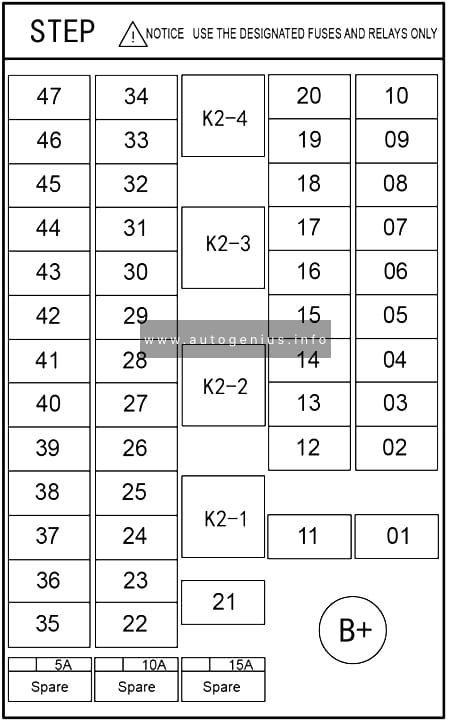
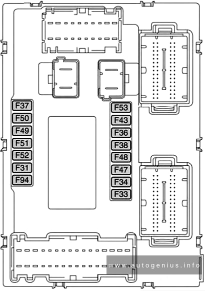
Fuse Box Diagram
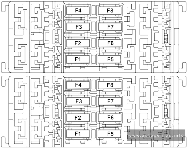
Assignment of the fuses in cargo compartment
| № | Amps | Description |
|---|---|---|
| Fuse Holder №1 | ||
| F1 | 20A Yellow | Sunroof |
| F2 | – | – |
| F3 | 30A Green | Power Liftgate Module (PLGM) |
| F4 | 5A Tan | Driver And Passenger Ventilated Seats (HMSM) |
| F5 | 25A Clear | Heating And Memory Drive Seat Module 1 |
| F6 | 10A Red | Heating And Memory Drive Seat Module 2 |
| F7 | 7.5A Brown | Driver And Passenger Lumbar Regulator (Without HMSM) |
| F8 | 20A Yellow | Passenger Seat SW (HMSM) |
| Fuse Holder №2 | ||
| F3 | 5A Tan | Hands-Free Power Liftgate (HFRM) |
| F4 | 7.5A Brown | Damping Control Module |
| F5 | 5A Tan | Changeover Valve Feed (ELCM) |
| F8 | 7.5A Brown | Damping Control Module |
| Maxi Fuse Holder | ||
| F01 | 30A Green | Amplifier On the Rear Cargo Fuse/Relay Distribution Unit bracket, there is a Maxi Fuse holder for the Amplifier (if equipped). |
WARNING: Terminal and harness assignments for individual connectors will vary depending on vehicle equipment level, model, and market.