Chery E3 (A19; 2013 – 2015) – fuse and relay box diagram

Chery E3 (A19; 2013 – 2015) – fuse and relay box diagram

Year of production: 2013, 2014, 2015


Passenger Compartment Fuse Panel

Fuse Box Location

Instrument panel fuse and relay box is located on the lower left side of instrument panel.
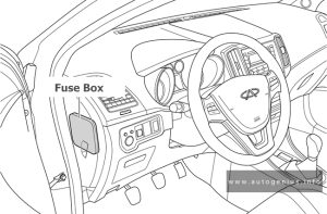
Chery E3 - fuse and relay box location - passenger compartment
Chery E3 – fuse and relay box location – passenger compartment


Fuse Box Diagram

Chery E3 - fuse and relay box diagram - passenger compartment
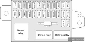
Chery E3 – fuse and relay box diagram – passenger compartment


Assignment of the fuses in the instrument panel 

Description
RF01 Instrument Cluster
RF02 Airbag
RF03 Diagnosis / Radar / A/C Control Panel / BCM
RF04 ECU
RF05 ABS
RF06 TCU (If equipped)
RF07 Front Wiper
RF08 Front Washer
RF09 Power Outside Rear View Mirror
RF10
RF11
RF12
RF14
RF15
RF16 Audio System / Sunroof Switch (If equipped)/ Blower Relay Coil / BCM
RF17 Cigarette Lighter
RF18
RF19 TCU (If equipped)
RF20 Sunroof (If equipped)
RF21 Key in Switch / Diagnosis / Stop Switch / lgnition Switch
RF22 Rear Fog Light
RF23 RF23
RF24 Position Switch (If equipped)
RF25 A/C Control Panel
RF26 Rear View Mirror Heating (If equipped)

BCM Fuse Box

It is located on lower side of instrument panel.

Chery E3 - fuse and relay box diagram - BCM fuse box
Chery E3 – fuse and relay box diagram – BCM fuse box


BCM fuse box

Description
1 Reserve
2 Rear Left Lifter / Rear Right Lifter
3 Reserve
4 High Pitched Horn / Low Pitched Horn
5 Dome Light / Front Left Map Light / Front Right Map Light / Key Light
6 Reserve
7 Trunk Lock / Door Lock Motor
8 Front Left Position Light / Rear Left Position Light
9 Front Right Position Light / Rear Right Position Light / Left License Plate Light / Right License Plate Light
10 Reserve
11 Reserve
12 Front Left Lifter / Front Right Lifter

Engine Compartment Fuse Box

Fuse Box Location

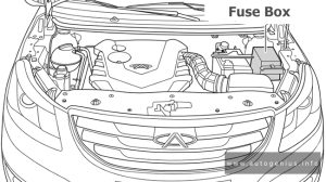
The fuse box is located on the left side of engine compartment and the rear side of front left combination light.
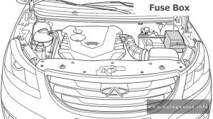
Chery E3 - fuse and relay box location - engine compartment
Chery E3 – fuse and relay box location – engine compartment


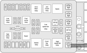
Fuse Box Diagram

Chery E3 - fuse and relay box diagram - engine compartment
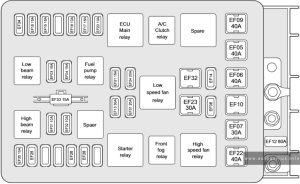
Chery E3 – fuse and relay box diagram – engine compartment


Assignment of the fuses in the engine compartment

Description
EF01 Left Headlight High Beam
EF02 Right Headlight High Beam
EF03 Left Headlight Low Beam
EF04 Right Headlight Low Beam
EF05 Instrument Panel Fuse and Relay Box
EF06 ABS Pump
EF07 Blower
EF08 Reserve
EF09 Ignition Switch
EF10 Reserve
EF12 BCM
EF13 Starter
EF14 Reserve
EF15 Upstream/Downstream Oxygen Sensor
EF16 Ignition Coil
EF17 ECU EMS
EF18 Canister / Fuel Pump / High-speed Fan Relay / Low-speed Fan Relay Coil
EF20 Injector
EF21 Fuel Pump
EF22 High-speed Fan
EF23 Low-speed Fan
EF24 A/C
EF25 Reserve
EF26 Reserve
EF28 Reserve
EF31 Front Fog Light
EF32 Reserve
EF33 Instrument Cluster / Audio System
EF34 Reserve
EF35 ECU

WARNING: Terminal and harness assignments for individual connectors will vary depending on vehicle equipment level, model, and market.

Chery Bonus 3 (A19; 2013 – 2015) – fuse and relay box diagram

Chery Bonus 3 (A19; 2013 – 2015) – fuse and relay box diagram

Year of production: 2013, 2014, 2015


Passenger Compartment Fuse Panel

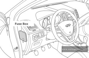
Fuse Box Location

Instrument panel fuse and relay box is located on the lower left side of instrument panel.

Chery Bonus 3 - fuse and relay box location - passenger compartment
Chery Bonus 3 – fuse and relay box location – passenger compartment

Fuse Box Diagram

Chery Bonus 3 - fuse and relay box diagram - passenger compartment
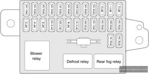
Chery Bonus 3 – fuse and relay box diagram – passenger compartment


Assignment of the fuses in the instrument panel 

Description
RF01 Instrument Cluster
RF02 Airbag
RF03 Diagnosis / Radar / A/C Control Panel / BCM
RF04 ECU
RF05 ABS
RF06 TCU (If equipped)
RF07 Front Wiper
RF08 Front Washer
RF09 Power Outside Rear View Mirror
RF10
RF11
RF12
RF14
RF15
RF16 Audio System / Sunroof Switch (If equipped)/ Blower Relay Coil / BCM
RF17 Cigarette Lighter
RF18
RF19 TCU (If equipped)
RF20 Sunroof (If equipped)
RF21 Key in Switch / Diagnosis / Stop Switch / lgnition Switch
RF22 Rear Fog Light
RF23 RF23
RF24 Position Switch (If equipped)
RF25 A/C Control Panel
RF26 Rear View Mirror Heating (If equipped)

BCM Fuse Box

It is located on lower side of instrument panel.

Chery Bonus 3 - fuse and relay box diagram - BCM fuse box
Chery Bonus 3 – fuse and relay box diagram – BCM fuse box


BCM fuse box

Description
1 Reserve
2 Rear Left Lifter / Rear Right Lifter
3 Reserve
4 High Pitched Horn / Low Pitched Horn
5 Dome Light / Front Left Map Light / Front Right Map Light / Key Light
6 Reserve
7 Trunk Lock / Door Lock Motor
8 Front Left Position Light / Rear Left Position Light
9 Front Right Position Light / Rear Right Position Light / Left License Plate Light / Right License Plate Light
10 Reserve
11 Reserve
12 Front Left Lifter / Front Right Lifter

Engine Compartment Fuse Box

Fuse Box Location

The fuse box is located on the left side of engine compartment and the rear side of front left combination light.

Chery Bonus 3 - fuse and relay box location - engine compartment
Chery Bonus 3 – fuse and relay box location – engine compartment


Fuse Box Diagram

Chery Bonus 3 - fuse and relay box diagram - engine compartment
Chery Bonus 3 – fuse and relay box diagram – engine compartment


Assignment of the fuses in the engine compartment

Description
EF01 Left Headlight High Beam
EF02 Right Headlight High Beam
EF03 Left Headlight Low Beam
EF04 Right Headlight Low Beam
EF05 Instrument Panel Fuse and Relay Box
EF06 ABS Pump
EF07 Blower
EF08 Reserve
EF09 Ignition Switch
EF10 Reserve
EF12 BCM
EF13 Starter
EF14 Reserve
EF15 Upstream/Downstream Oxygen Sensor
EF16 Ignition Coil
EF17 ECU EMS
EF18 Canister / Fuel Pump / High-speed Fan Relay / Low-speed Fan Relay Coil
EF20 Injector
EF21 Fuel Pump
EF22 High-speed Fan
EF23 Low-speed Fan
EF24 A/C
EF25 Reserve
EF26 Reserve
EF28 Reserve
EF31 Front Fog Light
EF32 Reserve
EF33 Instrument Cluster / Audio System
EF34 Reserve
EF35 ECU

WARNING: Terminal and harness assignments for individual connectors will vary depending on vehicle equipment level, model, and market.