Honda HR-V (US) (2023 – 2025) – fuse and relay box diagram
Year of production: 2023, 2024, 2025
This article focuses on the third-generation Honda HR-V (North American version) / Honda ZR-V, available from 2022 to the present. It includes fuse box diagrams for the 2023 and 2024 Honda HR-V (US) / ZR-V models, provides details on the locations of the fuse panels within the vehicle, and explains the function and layout of each fuse.
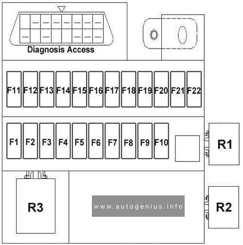
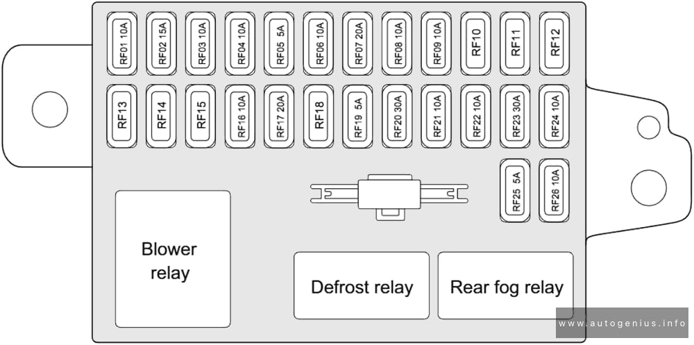
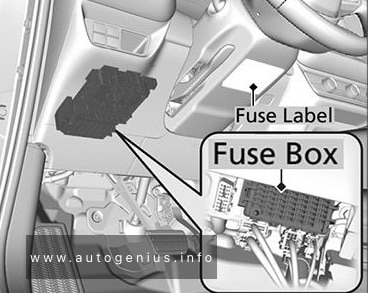
Passenger Compartment Fuse Panel
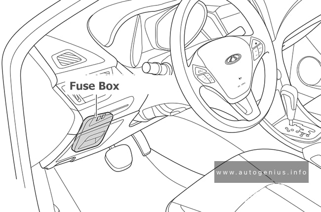
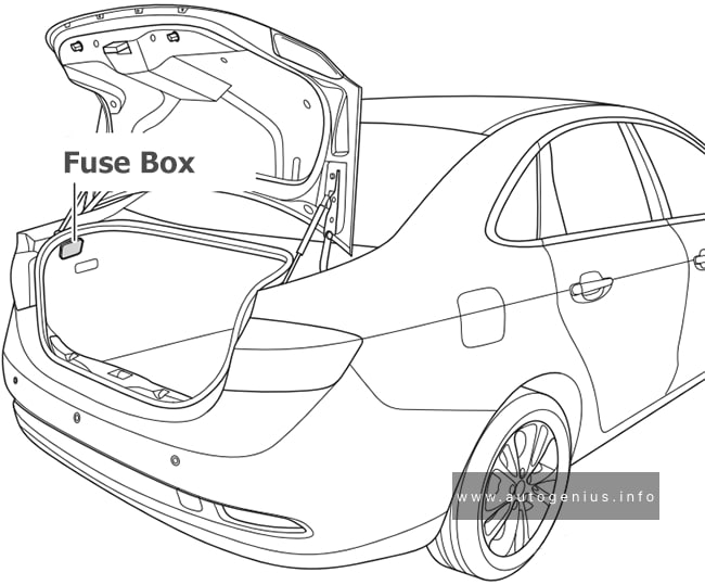
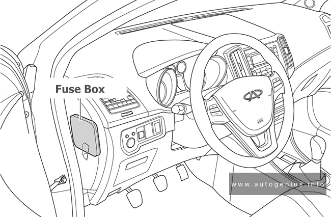
Fuse Box Location
The fuses are located under the dashboard. Fuse locations are shown on the label under the steering column.
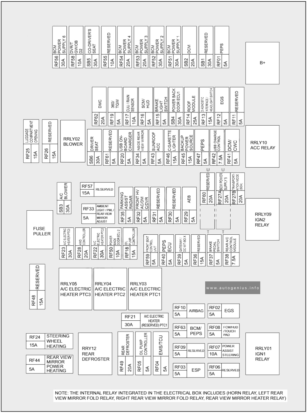
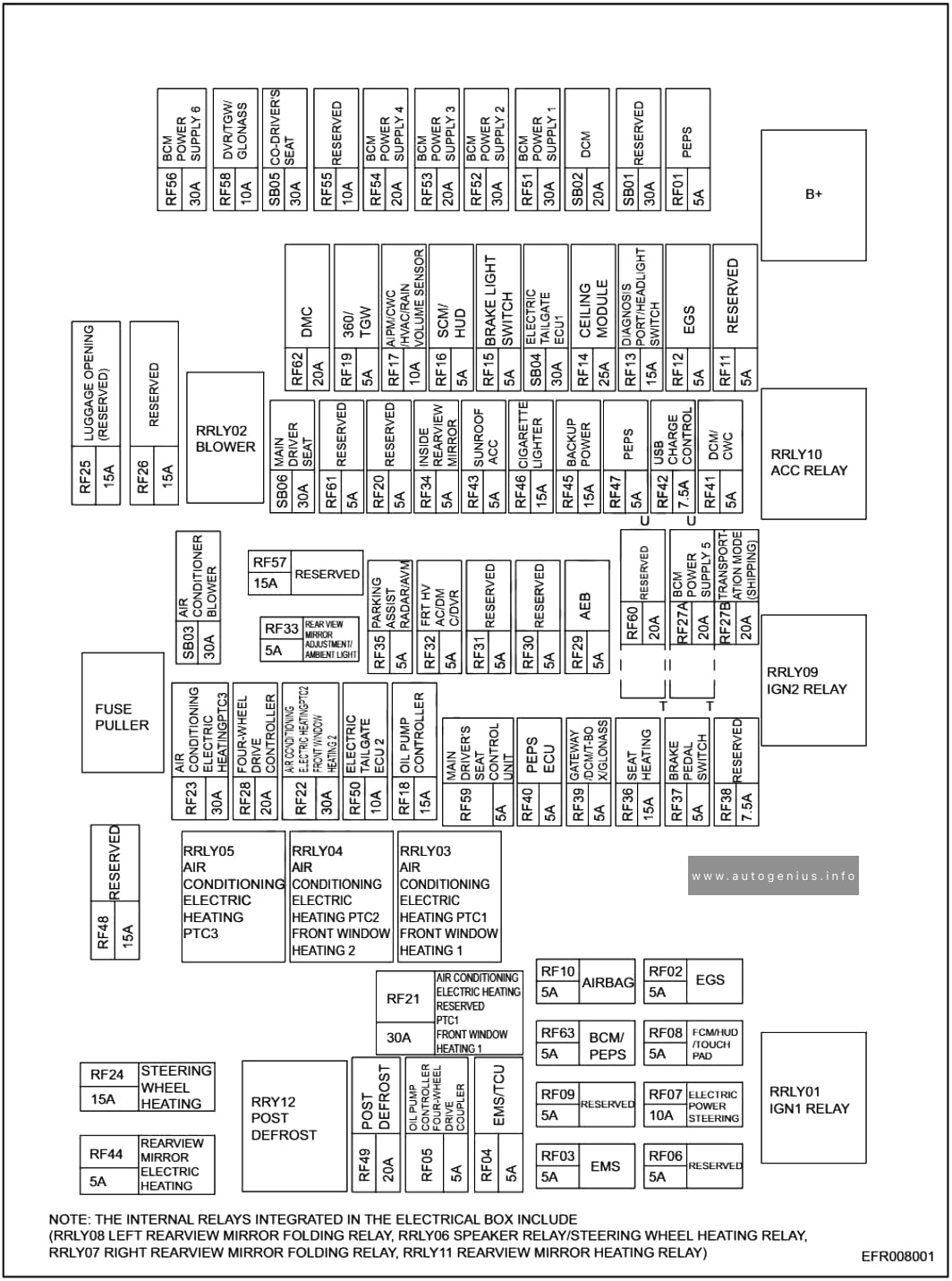
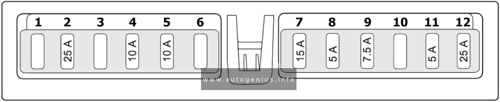
Fuse Box Diagram
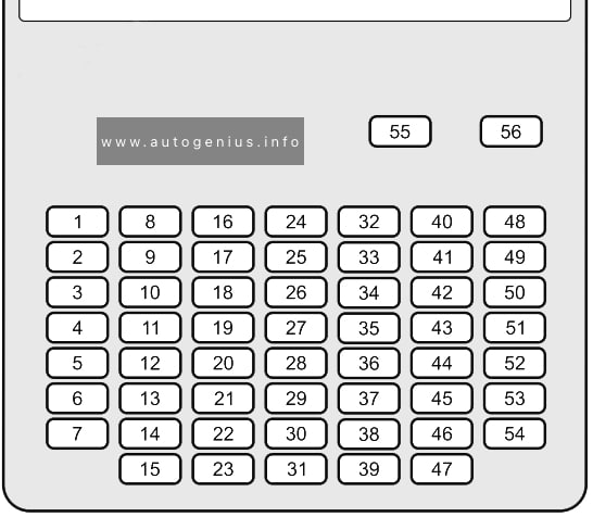
Assignment of the fuses in the instrument panel
| № | Amps | Circuit Protected |
|---|---|---|
| 1 | 20A | P/W DR |
| 2 | 20A | P/W AS |
| 3 | 20A | P/W RR R |
| 4 | 20A | P/W RR L |
| 5 | 10A | OPTION |
| 6 | 10A | SRS |
| 7 | 10A | T/G MTR |
| 8 | 10A | ZR-V: IDAS / HUD |
| 9 | 20A | ZR-V: FR ACC SOCKET |
| 10 | 20A | DOOR LOCK |
| 11 | 10A | METER |
| 12 | 10A | ST CUT RLY |
| 13 | 10A | OPTION2 |
| 14 | 10A | OPTION6 (VB SOL) |
| 15 | 10A | DR DOOR UNLOCK |
| 16 | 20A | SUNROOF |
| 17 | 10A | ZR-V: SBW |
| 18 | – | – |
| 19 | – | – |
| 20 | 10A | ZR-V: RR FOG |
| 21 | 20A | CARGO ACC SOCKET |
| 22 | 10A | SMART |
| 23 | 10A | DR DOOR LOCK |
| 24 | – | – |
| 25 | 10A | IMG |
| 26 | 10A | SRS |
| 27 | 10A | ACG |
| 28 | 10A | ABS/VSA |
| 29 | 20A | FUEL PUMP |
| 30 | 10A | L SIDE DOOR UNLOCK |
| 31 | 10A | R SIDE DOOR UNLOCK |
| 32 | – | – |
| 33 | 10A | USB CHG |
| 34 | – | – |
| 35 | – | – |
| 36 | 20A | ZR-V: PTG CLOSER |
| 37 | 20A | HR-V (US): E-PTL |
| 38 | 20A | ZR-V: IGA2 |
| 39 | 10A | R SIDE DOOR LOCK |
| 40 | 20A | P SEAT REC / RR HI |
| 41 | 20A | P SEAT SLIDE / FR HI |
| 42 | 10A | ZR-V: IG1 MON |
| 43 | 10A | A/C |
| 44 | 10A | DRL |
| 45 | 10A | ACC |
| 46 | 10A | ACC KEY LOCK |
| 47 | 10A | L SIDE DOOR LOCK |
| 48 | 20A | HR-V (US): H/SEAT ZR-V: FR H/SEAT |
| 49 | 20A | ZR-V: AS P SEAT REC |
| 50 | – | – |
| 51 | 20A | ZR-V: RR H/SEAT |
| 52 | 20A | HR-V (US): E-DPS |
| 53 | 20A | ZR-V: AS P SEAT SLIDE |
| 54 | 10A | OPTION 1 / FUEL LID |
| 55 | – | – |
| 56 | – | – |
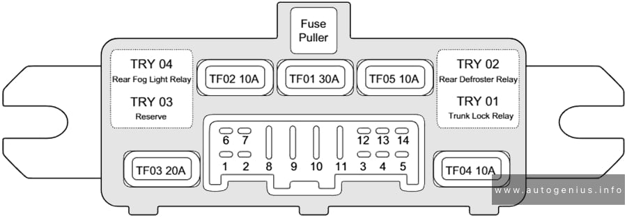
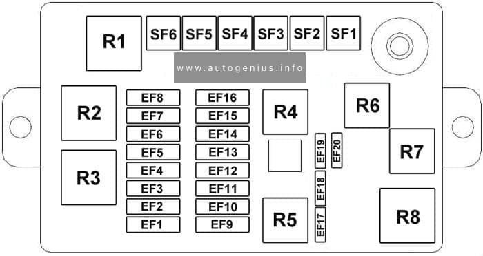
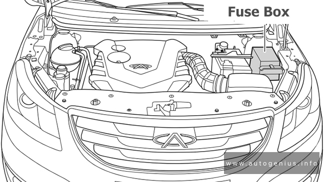
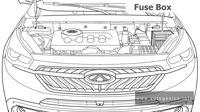
Engine Compartment Fuse Box
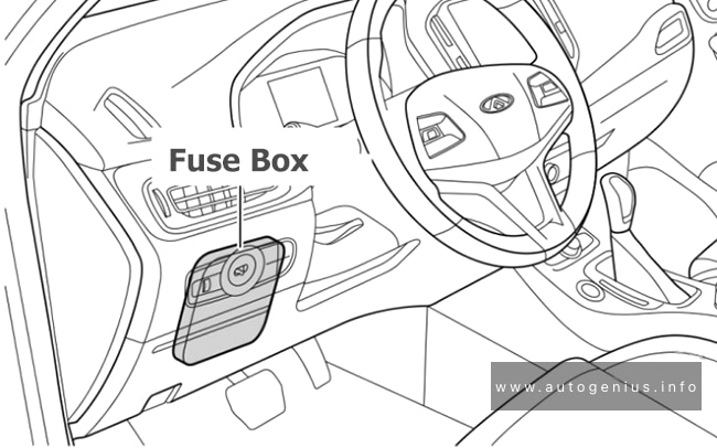
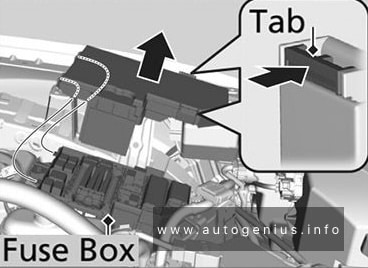
Fuse Box Location
The fuse box is located near the battery. Push the tabs to open the box. Fuse locations are shown on the fuse box cover.
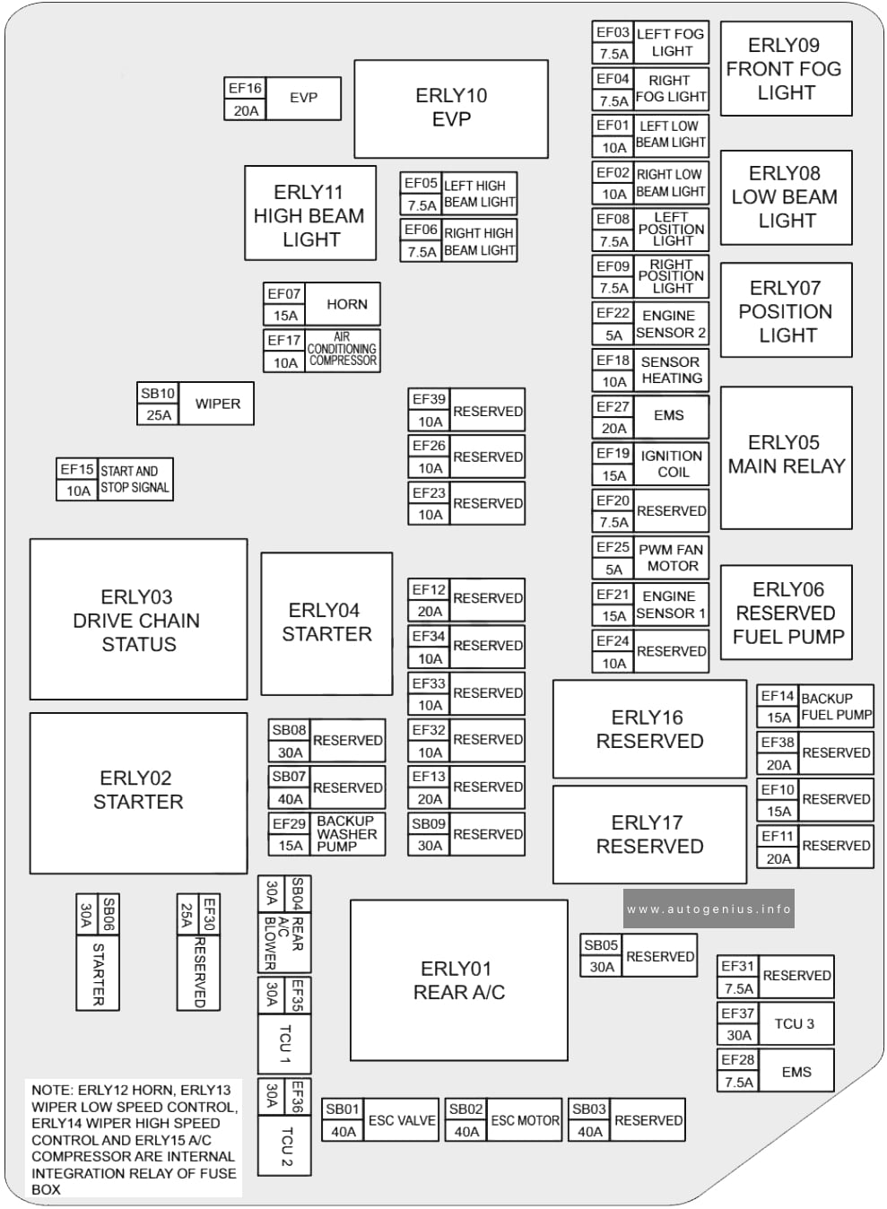
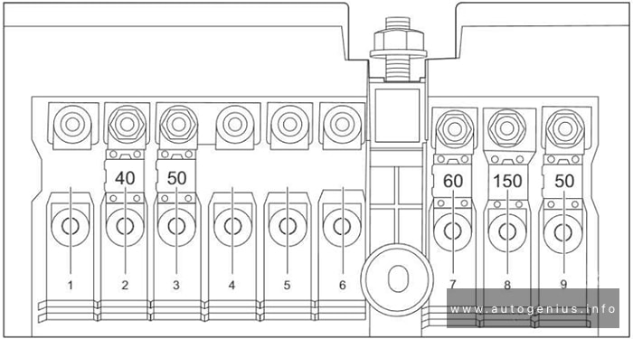
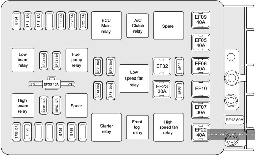
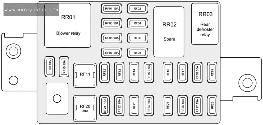
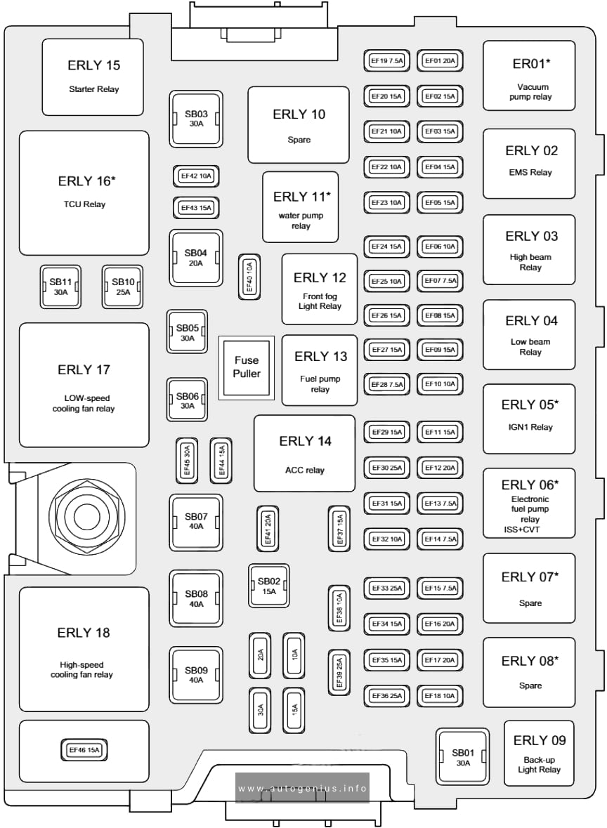
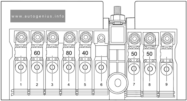
Fuse Box Diagram
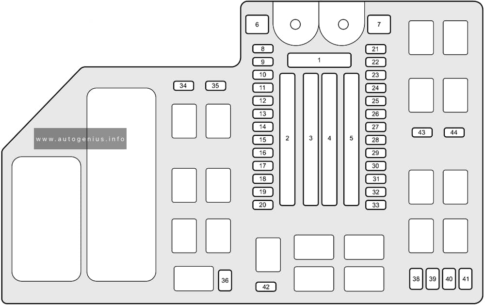
Assignment of the fuses in the engine compartment
| № | Amps | Circuit Protected |
|---|---|---|
| 1 | 125A | BATTERY |
| 2-1 | 40A | ZR-V: A/C PTC1 |
| 2-2 | 40A | – |
| 2-3 | 60A | F/BOX OPTION |
| 2-4 | 40A | – |
| 2-5 | 40A | F/BOX OPTION2 |
| 2-6 | 30A | – |
| 2-7 | 60A | F/BOX MAIN |
| 3-1 | 30A | – |
| 3-2 | 30A | – |
| 3-3 | 70A | – |
| 3-4 | 30A | RR DEFROSTER |
| 3-5 | 40A | ZR-V: PTG MTR |
| 3-6 | 30A | ZR-V: A/C PTC3 |
| 3-7 | 40A | HTR MTR |
| 4-1 | 30A | ZR-V: ESB |
| 4-2 | 40A | ABS/VSA MTR |
| 4-3 | 30A | ZR-V: RFC |
| 4-4 | 30A | ZR-V: P-ACT MTR |
| 4-5 | 30A | IG MAIN |
| 4-6 | 30A | ZR-V: OPTION6 |
| 4-7 | 30A | HR-V (US): IG MAIN2 |
| 5-1 | 30A | HR-V (US): ST MAGNETIC SW |
| 5-2 | 30A | WIPER |
| 5-3 | 70A | EPS |
| 5-4 | 30A | ZR-V: IG MAIN2 |
| 5-5 | 40A | ABS/VSA FSR |
| 5-6 | 30A/40A | HR-V (US): MAIN FAN ZR-V: F/BOX MAIN2 |
| 5-7 | 40A | F/BOX MAIN2 |
| 6 | 30A | HR-V (US): SUB FAN |
| 7 | 40A | HR-V (US): BOOSTER MTR |
| 8 | 20A/30A | ZR-V: AUDIO AMP |
| 9 | 20A | ZR-V: SUNSHADE |
| 10 | 7.5A | AUDIO SUB |
| 11 | 15A | HR-V (US): FR DEICER |
| 12 | 20A | ZR-V: SUPER LOCK |
| 13 | 10A | H/STRG |
| 14 | 10A | ZR-V: BATT IR |
| 15 | 15A | ZR-V: H/L ADJ |
| 16 | 10A | MG CLUTCH |
| 17 | 15A | WASHER |
| 18 | 10A | HORN |
| 19 | 15A | BACK UP |
| 20 | 15A | AUDIO |
| 21 | 20A | R/M1 |
| 22 | 15A | DBW |
| 23 | 20A | R/M2 |
| 24 | 10A | BACKUP FI-ECU |
| 25 | 15A | IGP |
| 26 | 10A/15A | HR-V (US): TCU ZR-V: DCU |
| 27 | 20A | LCM L |
| 28 | 20A | ZR-V: INJ |
| 29 | 10A | STOP |
| 30 | 20A | LCM R |
| 31 | 15A | IG COIL |
| 32 | 20A | ZR-V: EVTC |
| 33 | 15A | HAZARD |
| 34 | 10A | ZR-V: IGA |
| 35 | – | – |
| 36 | – | – |
| 37 | 30A | – |
| 38 | 10A | ZR-V: PCU EWP |
| 39 | 10A | ZR-V: P-ACT DRV |
| 40 | 7.5A/10A | ZR-V: IGB |
| 41 | 10A | IGPS (LAF) |
| 42 | 10A | IG1 MON2 |
| 43 | – | – |
| 44 | – | – |
WARNING: Terminal and harness assignments for individual connectors will vary depending on vehicle equipment level, model, and market.