The Chery Tiggo 8 PRO, a mid-size crossover, has been available since 2020 and continues to be produced. In this guide, you’ll find fuse box diagrams for the 2020, 2021, 2022, and 2023 models. It also provides information on the location of the fuse panels inside the vehicle, along with details about the fuse assignments (fuse layout) and relays.
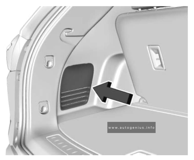
Passenger Compartment Fuse Panel
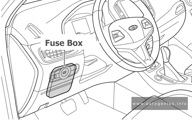
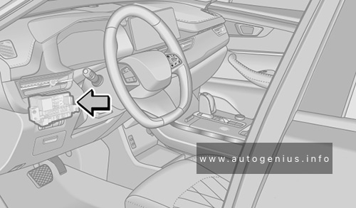
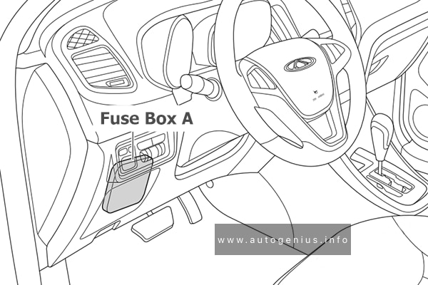
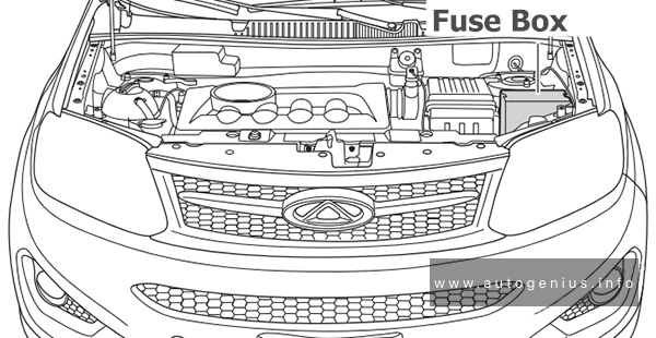
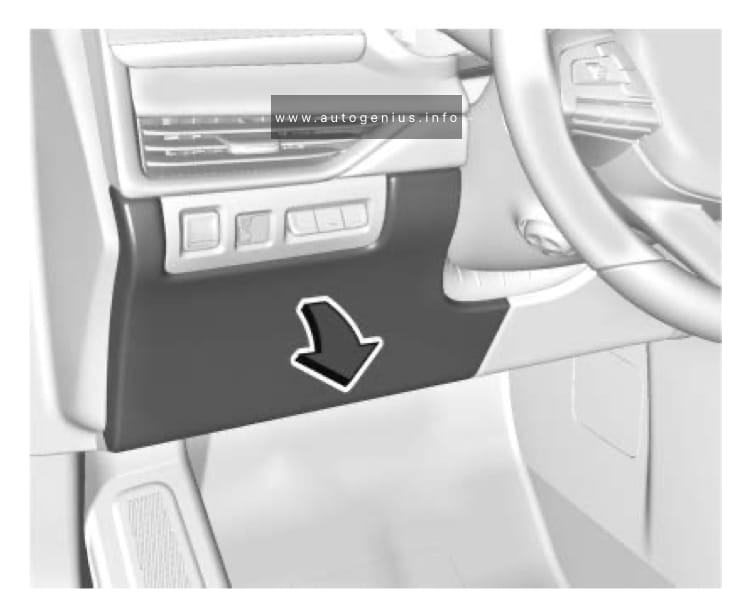
Fuse Box Location
The fuses are located on the lower left side of instrument panel.
Chery Tiggo 8 PRO (2020 – 2023) – fuse and relay box location – passenger compartment
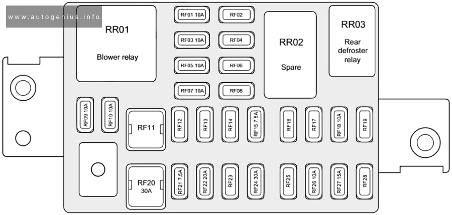
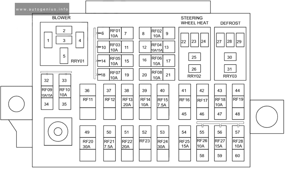
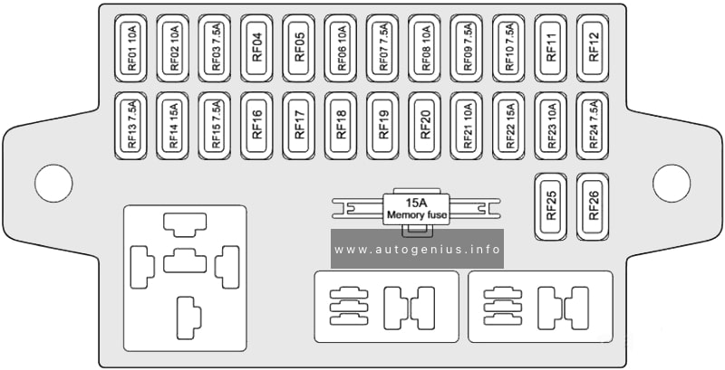
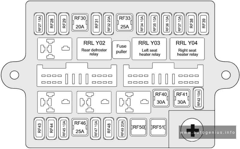
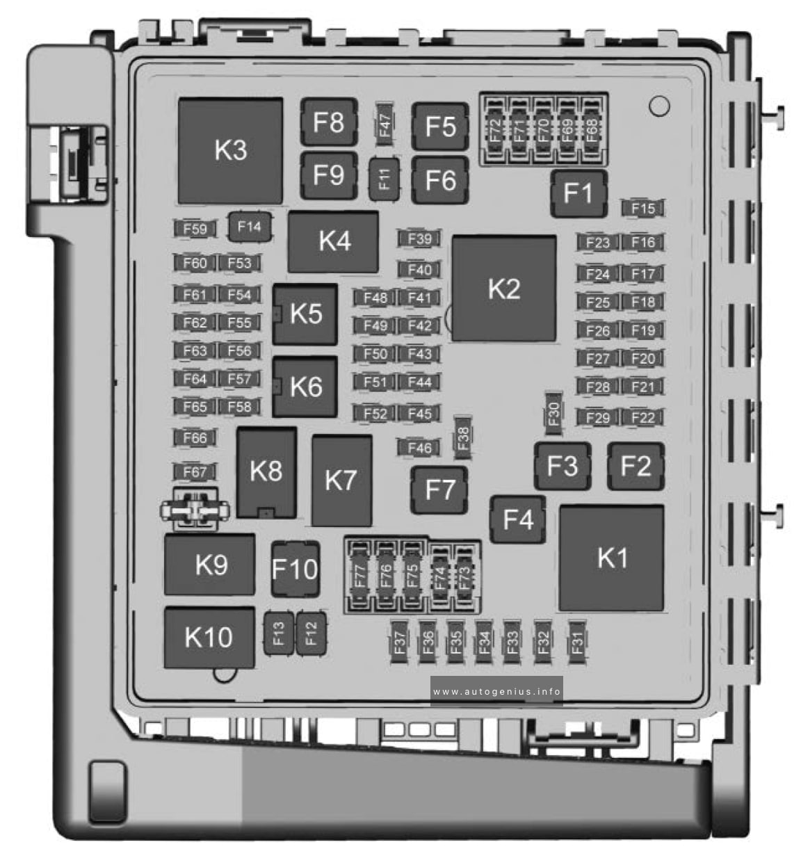
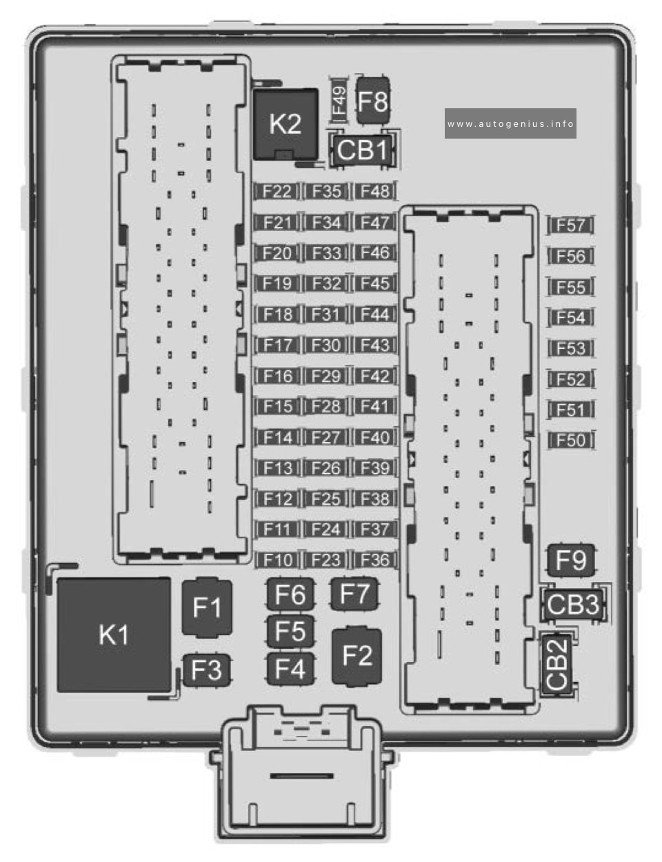
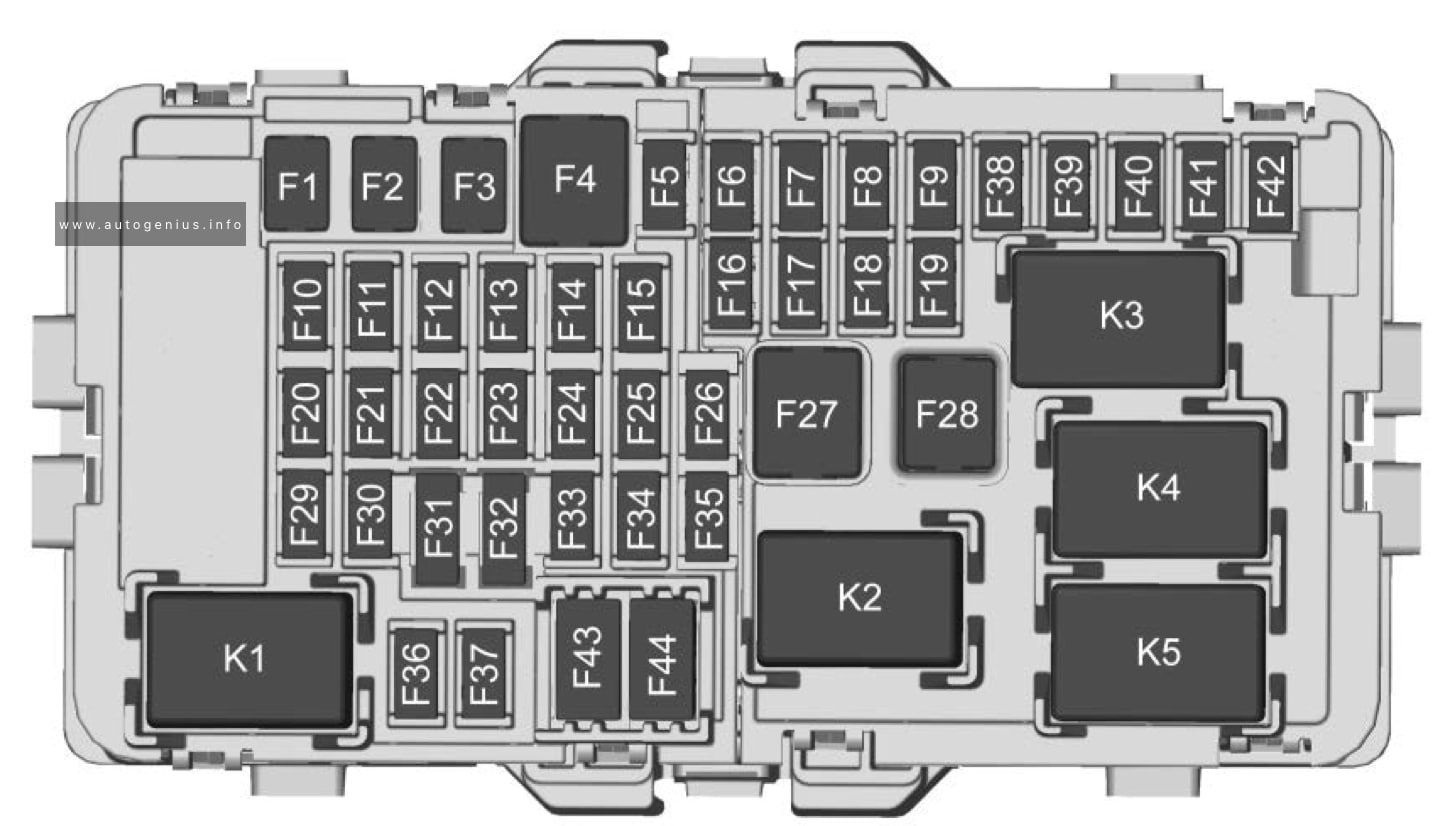
Fuse Box Diagrams
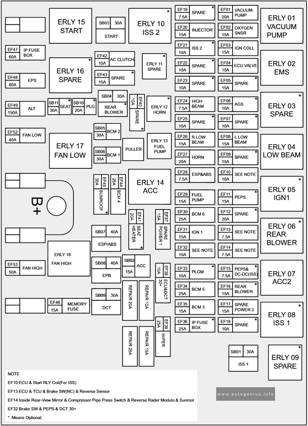
Chery Tiggo 8 PRO (2020 – 2023) – fuse and relay box diagram – passenger compartment (T1D)
Assignment of the fuses in the instrument panel
№
Description
RF01
BCM & Instrument Cluster & Gateway
RF02
–
RF03
EPS & Angle Sensor
RF04
Multi-View Camera System
RF05
Airbag Module
RF06
–
RF07
A/C Control Panel & Radio Control Module & Head Lamps Adjust Sw Power & TBOX & Shift Lever (DCT)
RF08
–
RF09
A/C Control Panel & Radio Contrl Module & TBOX & DCDC
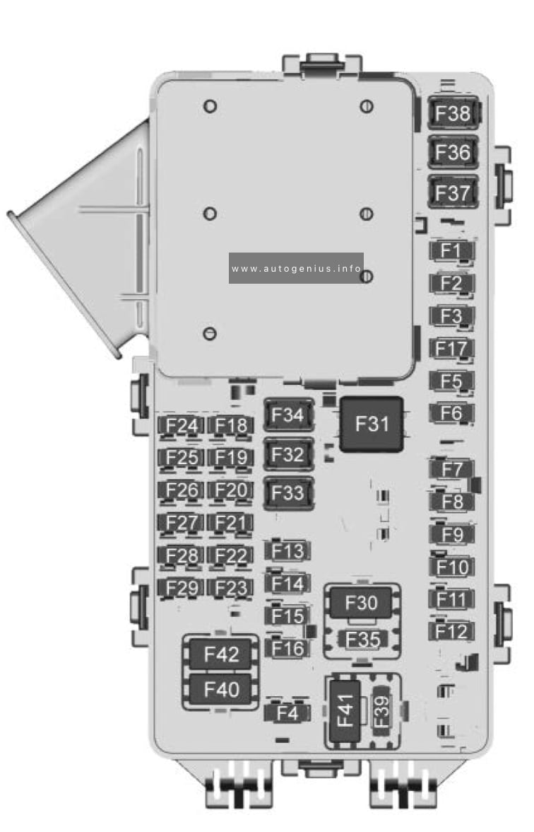
Assignment of the fuses in the passenger compartment
№
Usage
F1
Left Power Window
F2
Right Power Window
F3
—
F4
Direct Current to Direct Current Converter 2
F5
Auxiliary Power Outlet – Cargo
F6
Heated Seat Battery 1
F7
Heated Seat Battery 2
F8
Body Control Module 3 – LED Headlamp Low Beam Right Control Signal, Right Front Turn Lamp Control Signal, Left Front Side Marker and Auxiliary Park, Left Rear Tail/Side Marker Control Signal, Left Daytime Running Lamps Control Signal
F9
Electric Park Brake
F10
Body Control Module 2 (Stop/Start) – Interior Lamps Control Signal, Door Handle Puddle Lamp (LED), Left Cornering Lamp, Right Cornering Lamp, Interior Lamps Control Signal, Backup Lamp Supply Voltage, License Plate Lamp Control Signal, Rear Closure Cargo Lamp Control Signal, Center High Mounted Stop Lamp LED Lamp Control Signal
F11
—
F12
—
F13
—
F14
—
F15
Transmission Control Module (Stop/ Start)
F16
Amplifier
F17
F18
Video Processing Module
F19
Power Steering Column
F20
Body Control Module 6 – LED Backlight Control, Interior Lighting Inadvertent Load Control Signal, Fuel Door Lock Control Signal, LED Backlight Control Signal
F21
Body Control Module 4 – LED Headlamp Low Beam Left Control Signal, Right Front Side Marker and Auxiliary Park, Right Rear Tail/ Side Marker Control Signal, Left Rear Stop Lamp Control Signal, Left Rear Stop/Turn Lamp Control Signal, Right DRL Control Signal
F22
Body Control Module 7 – Right Rear Stop Lamp Control Signal, Right Rear Stop/ Turn Lamp Control Signal, Left Front Turn Lamp Control Signal, Right Rear Turn Control Signal
F23
—
F24
Airbag
F25
Data Link Connector
F26
—
F27
—
F28
—
F29
Body Control Module 8 – Internal Driver/Fuel Door Unlock Relay Control Signal, Internal Non-Driver Door Lock Relay Control Signal, Internal All Door Unlock Relay Control Signal
F30
Overhead Console
F31
Steering Wheel Controls
F32
—
F33
Heating Ventilation and Air Conditioning Control Module
F34
Central Gateway Module
F35
Heated Seat Switch/Hazard Switch
F36
Wireless Charger Module/USB Charge Port
F37
—
F38
OnStar
F39
Shifter Interface Board/Center Stack/Head Up Display/ Instrument Panel Cluster/HVAC Display
F40
Long Range Radar Sensor/ Ultrasonic Park Assist Module/Camera Module/External Object Calculating Module/ Side Blind Zone Alert Modules/Front Camera Module
F41
Body Control Module 1 (Stop/Start) – LED Indicator Lighting Control, Accessory LED Control, Run-Start LED Control, Ambient Lighting LED Control 2, Liftgate Latch Motor Control Signal, Rear Wiper Control Signal, High Beam Lamp Control (Direct Drive), Rear Fog LED Lamp Control Signal, Windshield Washer Pump Motor Control Signal, Run/Crank Relay Control Signal, ECM/TCM ACC Wakeup Control Signal, Left Rear Turn Control Signal, Rear Wiper Wash Pump Control Signal, Brake Pedal Apply Signal
F42
Radio
F43
Console Auxiliary Power Outlet (Circuit Breaker)
F44
Front Console Auxiliary Power Outlet
Relay
K1
—
K2
Retained Accessory Power
K3
—
K4
—
K5
—
K5
Not Used
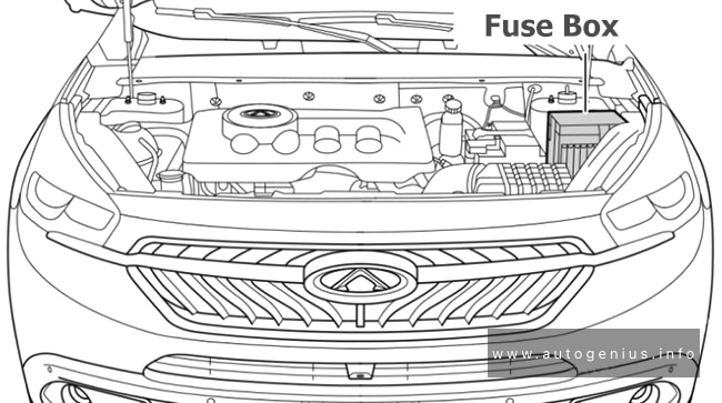
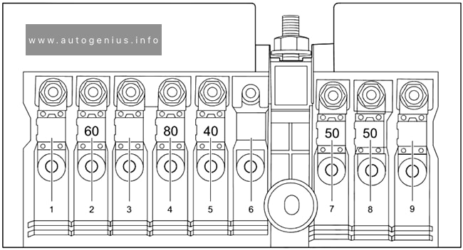
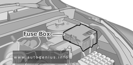
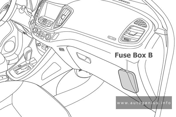
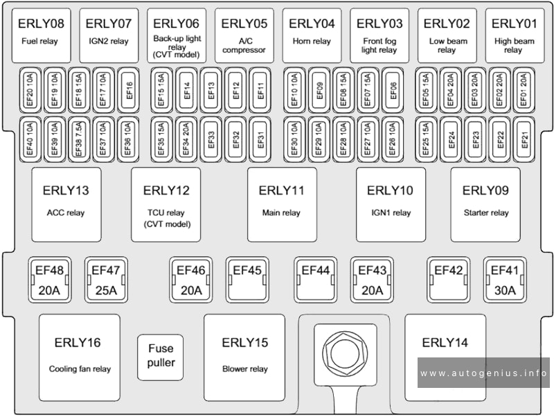
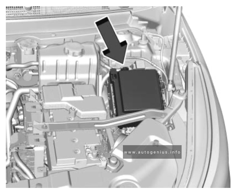
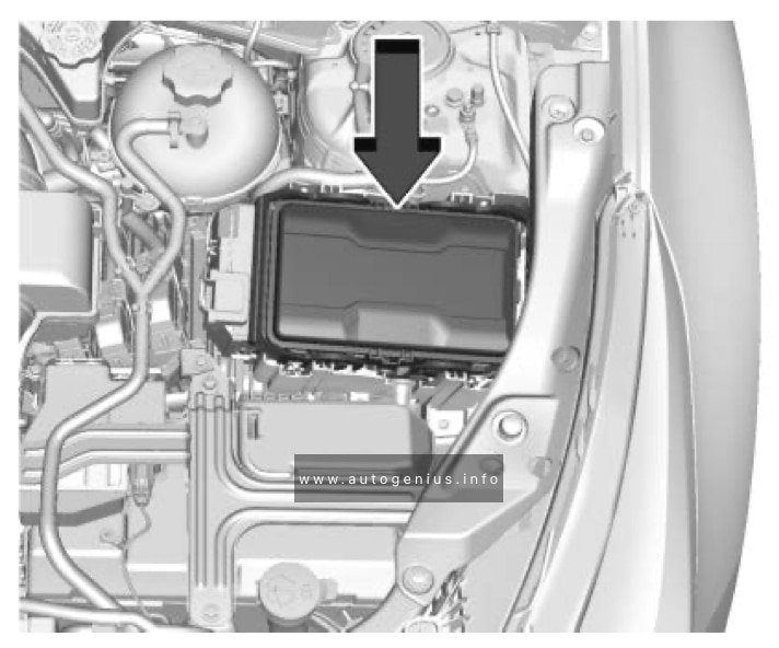
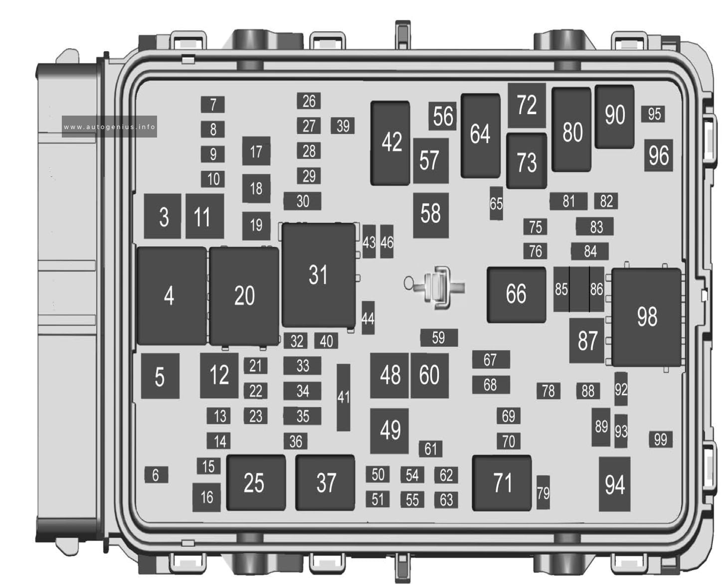
Engine Compartment
Fuse Box Location
The instrument panel fuse block is in the center console between the driver and passenger seats.
Driver Power Seat/ Memory Seat Module/ Driver Seat Massage Control
21
Power Sunroof
22
—
23
—
26
Transmission Control Module/Ignition
27
Inside Rear View Mirror, Shifter Interface Board Module Run/Crank, Central Gateway Module Run/Crank, Heating Ventilation and Air Conditioning Control Module Run/Crank ignition 3
28
Rear Wiper
29
—
30
Fuel Tank Zone Module Run/Crank, Direct Current to Direct Current Transformer Run/Crank, Electronic Brake Control Module Run/Crank, Instrument Panel Cluster Run/Crank
32
Rear Drive Control Module 1
33
Front Heated Seat Power 2
34
Liftgate Module / Front Window Switches
35
—
36
Fuel Tank Zone Module
39
Driver Seat Massage / Passenger Seat Massage
40
—
41
—
43
Heated Steering Wheel
44
Front Heated Seat Power Feed 1 / Front Vented Seats/ Rear Heated Seats
46
Engine Control Module Ignition
48
Rear Drive Control Module 2
49
Heating Ventilation and Air Conditioning Control Blower Motor
50
Spare
51
Spare
54
Spare
55
Spare
56
Starter Motor
57
—
58
—
59
High Beam Headlamps
60
—
61
Spare
62
Spare
63
Spare
65
Air Conditioning Clutch
67
Spare
68
Spare
69
—
70
Trailer Park Lamp
—
72
Starter Pinion
75
Engine Control Module Main
76
Powertrain Off Engine, Engine Control Module Power Train Ignition 1
78
Horn
79
Front and Rear Washer Pump
81
Engine Control Module Battery/Spare
82
—
83
Ignition Coils
84
Canister Purge Solenoid / Step Cam Exhaust Solenoid Cylinder 2 and 3 / Step Cam Intake Cylinder Solenoids / Turbo Bypass Solenoid / Oxygen Sensor (Pre) / O2 Heater / Oxygen Heated Sensor / Mass Airflow / Inlet Air Temperature / Throttle Inlet Absolute Pressure / Coolant Flow Control Valve
The Volvo V60 (2021) is a luxury midsize wagon that blends Scandinavian design, cutting-edge technology, and exceptional safety features. Known for its versatility and elegant style, the 2021 V60 offers a refined driving experience, practical cargo space, and a range of efficient powertrains, including plug-in hybrid options. As part of Volvo’s continued commitment to sustainability, the V60 is an eco-conscious choice that doesn’t sacrifice performance or luxury.
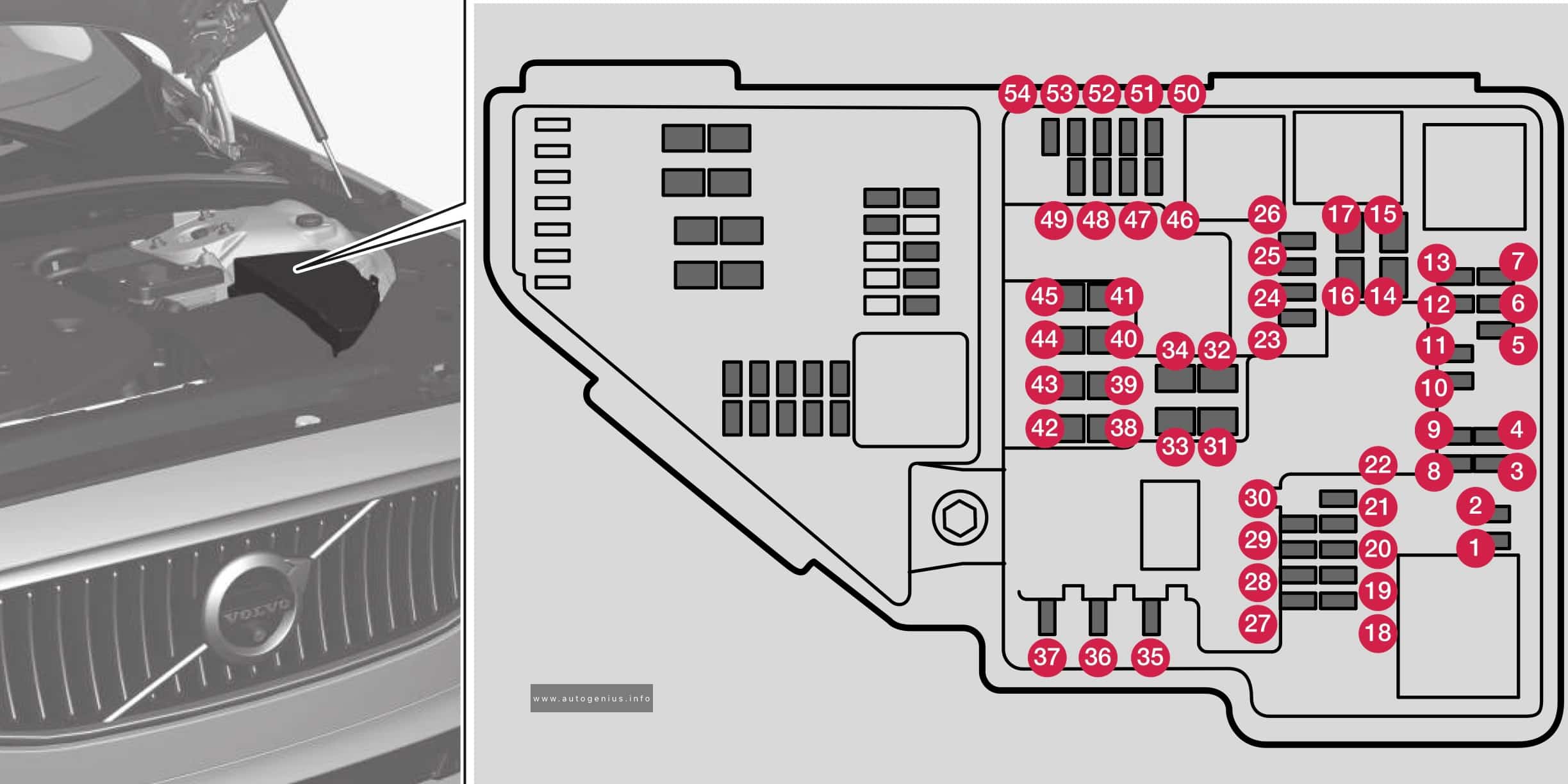
Engine compartment
Fuse box location and diagram
Volvo V60 – fuse and relay location and diagram – engine compartment
Assignment of fuses in the engine compartment (2021)
Spoiler damper control module; Cooler damper control module; Relay coils for output pulse (diesel); Coolant valve Fuel leakage detection (gasoline)
12
15
Coolant pump
13
20
Engine control module
14
40
Starter motor
15
Shunt
Starter motor
16
30
Fuel filter heater (diesel)
17
–
–
18
5
Calculation module
19
–
–
20
–
–
21
15
ECM camera
22
–
–
23
7.5
Front USB port in tunnel console, rear
24
15
12 V outlet in tunnel console, front
25
–
–
26
15
12 V outlet in trunk/cargo compartment
27
–
–
28
15
Driver-side headlight, LED
29
15
Passenger-side headlight, LED
30
–
–
31
–
–
32
–
–
33
25
Headlight washers
34
25
Washer fluid pump
35
15
Transmission control module; Electric gear selector
36
20
Horn
37
5
Alarm siren
38
40
Brake system control module (valves, parking brake)
38
30
Brake control with 48 V battery
39
30
Wipers
40
25
Rear window washer
41
–
–
42
20
Parking heater
43
–
–
44
–
–
45
–
–
46
5
Fed when ignition is on: engine control module, transmission components, electrical power steering, central electrical module, brake system control module
Volvo V60 – fuse and relay location and diagram – engine compartment (town engine)
Assignment of fuses in the engine compartment (2021, Recharge PHEV)
№
Ampere
Function
1
–
–
2
–
–
3
–
–
4
5
Control module for actuator for engaging/changing gears, automatic transmission
5
5
High-voltage coolant heater control module
6
5
Control module for A/C; heat exchanger cut-off valve; cut-off valve for coolant through the climate system
7
5
Hybrid battery control module; high-voltage converter for combined high-voltage generator/starter motor with 500V-12V voltage converter
8
–
–
9
10
Converter for controlling feed to rear axle electric motor
10
10
Hybrid battery control module; high-voltage converter for combined high-voltage generator/starter motor with 500V-12V voltage converter
11
5
Charge module
12
15
Cut-off valve for hybrid battery coolant; coolant pump 1 for hybrid battery
13
15
Coolant pump for electric drive system
14
25
Hybrid component cooling fan
15
–
–
16
–
–
17
–
–
18
5
Calculation module
19
–
–
20
–
–
21
–
–
22
–
–
23
7.5
Front USB port in tunnel console, front
24
15
12 V outlet in tunnel console, front
25
–
–
26
15
12 V outlet in trunk/cargo compartment
27
–
–
28
15
Driver-side headlight, LED
29
15
Passenger-side headlight, LED
30
–
–
31
–
–
32
–
–
33
25
Headlight washers
34
25
Windshield washer
35
–
–
36
20
Horn
37
5
Alarm siren
38
30
Brake system control module (valves, parking brake)
39
30
Wipers
40
25
Rear window washer
41
–
–
42
20
Parking heater
43
–
–
44
–
–
45
–
–
46
5
Fed when ignition is on: Engine control module; transmission components, electrical power steering, central electrical module
47
5
Exterior vehicle sound (certain markets)
48
15
Passenger-side headlight, LED
49
–
–
50
–
–
51
–
–
52
5
Airbags; Passenger weight sensor
53
15
Driver-side headlight, LED
54
5
Accelerator pedal sensor
55
15
Transmission control module; gear selector control module
56
5
Engine control module
57
–
–
58
–
–
59
–
–
60
–
–
61
20
Engine control module; actuator; throttle unit; turbo-charger valve
62
10
Solenoids, Fuel leakage control valve; Overpressure coupling
63
7.5
Vacuum regulator; Electric bypass valve: Ventilation valve
64
5
Spoiler damper control module; Cooler damper control module
Fuel leakage control pump
65
–
–
66
15
Heated oxygen sensor front and rear
67
15
Oil pump solenoid; A/C magnetic coupling; Heated oxygen sensor front, center and rear
68
–
–
69
20
Engine control module
70
15
Ignition coils; spark plugs
71
–
–
72
–
–
73
30
Transmission oil pump control module
74
–
–
75
–
–
76
–
–
77
–
–
78
–
–
77
–
Not Used
78
–
Not Used
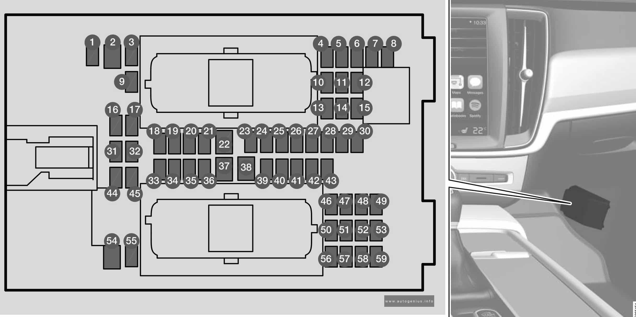
Passenger compartment
Fuse box location and diagram
Volvo V60 – fuse and relay location and diagram – passenger compartment
Assignment of fuses under the glove compartment (2021)
№
Ampere
Function
1
10
Medium voltage module (Vehicles with 48 V support battery only)
2
–
–
3
–
–
4
5
Movement sensor
5
–
–
6
5
Instrument panel
7
5
Center console buttons
8
5
Sun sensor
9
–
–
10
–
–
11
5
Steering wheel module
12
5
Module for start knob and parking brake controls
13
15
Heated steering wheel module
14
–
–
15
–
–
16
–
–
17
–
–
18
10
Climate system control module
19
–
–
20
10
Data link connector OBD-II
21
5
Center display
22
40
Climate system blower module (front)
23
5
USB HUB
24
7.5
Instrument lighting; Interior lighting; Rearview mirror auto-dim function; Rain and light sensors; Rear tunnel console keypad, rear seat; Power front seats; Rear door control panels; Climate system blower module left/right
25
5
Control module for driver support functions
26
20
Panoramic roof with sun curtain
27
5
Head-up display
28
5
Passenger compartment lighting
29
5
Wireless charging pad
30
5
Ceiling console display (seat belt reminder/front passenger side airbag indicator)
31
–
–
32
–
–
33
–
–
34
10
Fuses in the trunk/cargo compartment
35
5
Control module for Internet-connected vehicle; Control module for Volvo On Call
36
20
Door module in left-side rear door
37
40
Infotainment control module (amplifier)
38
–
–
39
5
Multi-band antenna module
40
5
Front seat massage function
41
–
–
42
15
Rear window wiper
43
15
Fuel pump control module
44
5
Relay coil for transmission oil pump
Converter medium voltage; Integrated starter motor
45
5
Opening trunk/tailgate with foot movement
46
15
Driver’s seat heating
47
15
Front passenger’s seat heating
48
7.5
Coolant pump
49
–
–
50
20
Door module in left-side front door
Recharge PHEV: Power driver’s seat
51
20
Active chassis control module
52
–
–
53
10
Sensus control module
54
–
–
55
–
–
56
20
Door module in right-side front door
Recharge PHEV: Power front passenger seat
57
–
–
58
5
TV (certain markets only)
59
15
Primary fuse for fuses 52, 53, 57 and 58
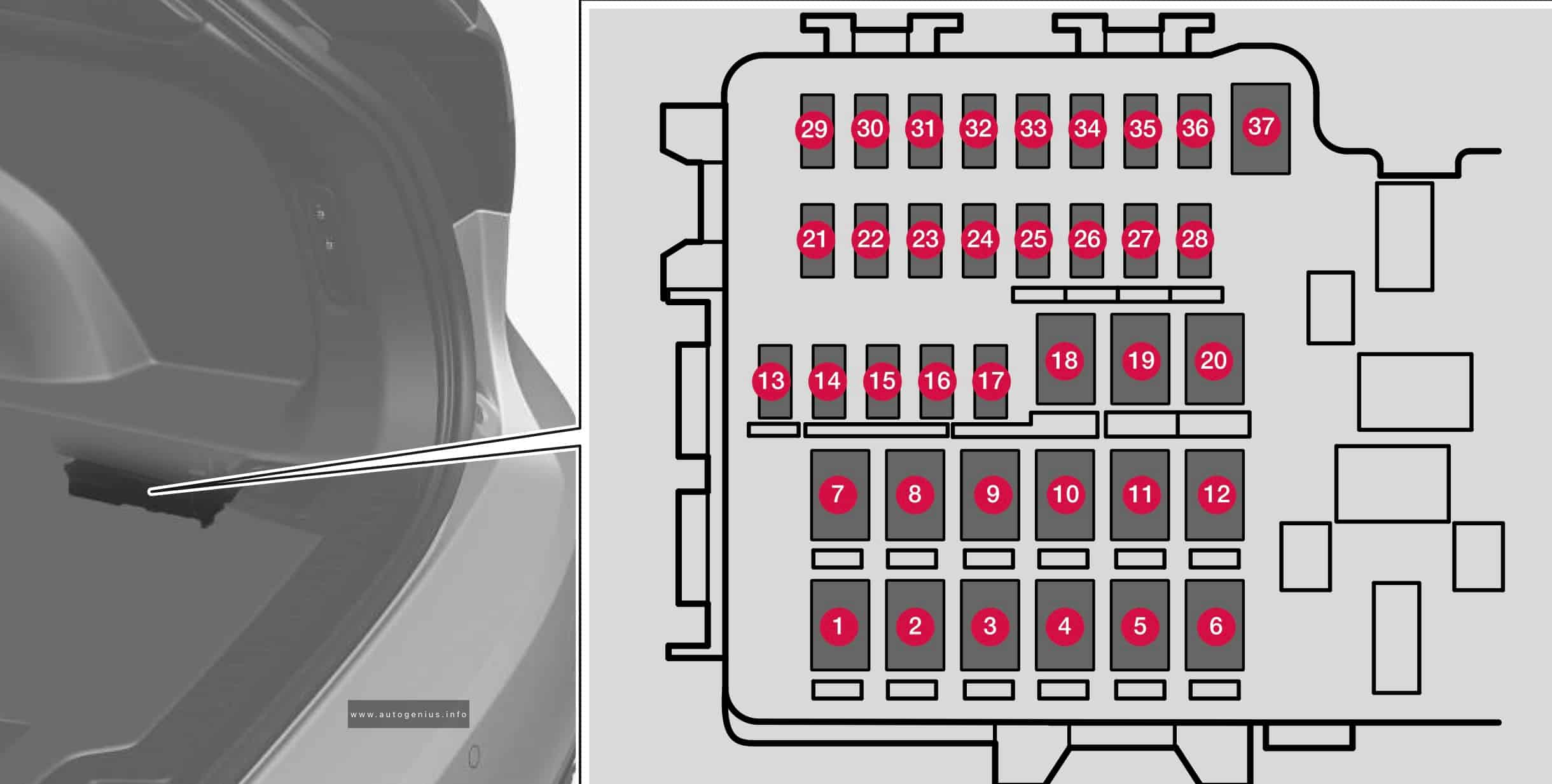
Cargo compartment
Fuse box location and diagram
Volvo V60 – fuse and relay location and diagram – cargo compartment
Assignment of fuses in the trunk (2021)
№
Ampere
Function
1
–
–
2
40
Recharge PHEV: Central electrical module
3
40
Pneumatic suspension compressor
4
–
–
5
–
–
6
–
–
7
20
Door module right side, rear
8
–
–
9
25
Power tailgate
10
20
Power front passenger seat
Door module right side, front
11
40
Towbar control module
12
40
Seat belt tensioner module (right side)
13
5
Internal relay windings
14
–
–
15
20
Door module left side, rear
16
5
USB hub/accessory port
17
–
–
18
25
Towbar control module
18
40
Accessory module
19
20
Power driver seat
Door module left side, front
20
40
Seat belt tensioner module (left side)
21
5
Park Assist Camera
22
–
–
23
–
–
24
–
–
25
10
Recharge PHEV: Feed when ignition is on
26
–
–
27
–
–
28
15
Heated rear seat (left side)
29
–
–
30
5
Blind Spot Information (BUS)
Exterior reverse signal control module
31
–
–
32
5
Seat belt tensioner module, right
33
5
Emissions system actuator (gasoline, certain engine variants)
34
–
–
35
15
All Wheel Drive (AWD) control module
36
15
Heated rear seat (right side)
37
–
–
WARNING: Terminal and harness assignments for individual connectors will vary depending on vehicle equipment level, model, and market.
The Volvo V60 (2020) is a premium midsize luxury wagon, combining Volvo’s renowned safety features with a blend of Scandinavian design, versatile practicality, and advanced technology. Continuing the success of the second-generation model launched in 2019, the 2020 V60 offers a range of powertrains, including fuel-efficient engines and a plug-in hybrid option, making it a sophisticated choice for those seeking both performance and eco-friendliness.
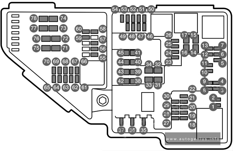
Engine compartment
Fuse box location and diagram
Volvo V60 – fuse and relay location and diagram – engine compartment
Assignment of fuses in the engine compartment (2020)
Engine control module; Actuator; Throttle unit; EGR valve (diesel); Position sensor for turbo (diesel); Valve for turbocharger (petrol)
8
5
Engine Control Module (ECM)
9
–
–
10
10
Solenoids (petrol); Valve; Thermostat for engine cooling system (petrol); Cooling pump for EGR (diesel); Glow control unit (diesel); Supercharger clutch (petrol); Crankshaft ventilation heater (diesel); Valve, gearbox oil cooler (diesel)
11
5
Control module for spoiler damper; Control module for radiator damper; Relay coils for output pulse (diesel)
12
15
Coolant pump
13
20
Engine Control Module (ECM)
14
40
Starter motor
15
Shunt
Starter motor
16
30
Fuel filter heater (diesel)
17
–
–
18
5
Calculation unit
19
–
–
20
–
–
21
–
–
22
–
–
23
–
–
24
15
12 V socket in tunnel console, front
25
15
12 V socket in tunnel console, by legroom for second seat row
26
15
12 V socket in cargo area
27
–
–
28
15
Left-hand headlamp, LED
29
15
Right-hand headlamp, LED
30
–
–
31
Shunt
Heated windscreen, left-hand side
32
40
Heated windscreen, left-hand side
33
25
Headlamp washers
34
25
Washer fluid pump
35
15
Transmission control unit; Electric gear selector
36
20
Horn
37
5
Siren
38
40
Control module for brake system (valves, parking brake)
38
30
Brake control with 48V battery
39
30
Windscreen wipers
40
25
Rear window washer
41
40
Heated windscreen, right-hand side
42
20
Parking heater
43
–
–
44
–
–
45
Shunt
Heated windscreen, right-hand side
46
5
Supplied when the ignition is switched on: Engine control module; Transmission components; Electric steering servo; Central electronic module; Control module for brake system
Volvo V60 – fuse and relay location and diagram – engine compartment (town engine)
Assignment of fuses in the engine compartment (2020, Twin Engine)
№
Ampere
Function
1
–
–
2
–
–
3
–
–
4
5
Control module for actuator for engagement/change of automatic gearbox gear positions
5
5
Control module for the high-voltage heater of the internal combustion engine’s coolant
6
5
Control module for air conditioning; Shut-off valve for heat exchanger; Shut-off valve for coolant that passes through the climate control system
7
5
Control module for hybrid battery; High voltage converter for combined high-voltage generator/starter motor with voltage converter 500V-12V
8
–
–
9
10
Converter for control of the supply to the rear axle’s electric motor
10
10
Control module for hybrid battery; High voltage converter for combined high-voltage generator/starter motor with voltage converter 500V-12V
11
5
Charging unit
12
15
Shut-off valve for the hybrid battery’s coolant; Coolant pump 1 for hybrid battery
13
15
Coolant pump for electric drive system
14
25
Cooling fan for hybrid components
15
–
–
16
–
–
17
–
–
18
5
Calculation unit
19
–
–
20
–
–
21
–
–
22
–
–
23
–
–
24
15
12 V socket in tunnel console, front
25
15
12 V socket in tunnel console, by legroom for second seat row
26
15
12 V socket in cargo area, USB ports in head restraints right/left
27
–
–
28
15
Left-hand headlamp, LED
29
15
Right-hand headlamp, LED
30
–
–
31
Shunt
Heated windscreen, left-hand side
32
40
Heated windscreen, left-hand side
33
25
Headlamp washers
34
25
Windscreen washers
35
–
–
36
20
Horn
37
5
Siren
38
40
Control module for brake system (valves, parking brake)
39
30
Windscreen wipers
40
25
Rear window washer
41
40
Heated windscreen, right-hand side
42
20
Parking heater
43
40
Control unit for brake system (ABS pump)
44
–
–
45
Shunt
Heated windscreen, right-hand side
46
5
Supplied when the ignition is switched on: Engine control module; Transmission components; Electric steering servo; Central electronic module
47
5
Exterior car noise (certain markets)
48
15
Right-hand headlamp, LED
49
5
Alcohol lock
50
–
–
51
–
–
52
5
Airbags; Passenger weight sensor
53
15
Left-hand headlamp, LED
54
5
Accelerator pedal sensor
55
15
Transmission control module; Control module for gear selector
56
5
Engine Control Module (ECM)
57
–
–
58
–
–
59
–
–
60
–
–
61
20
Engine control module; Actuator; Throttle unit; Valve for turbocharger
62
10
Solenoids; Valves; Overpressure connection
63
7,5
Vacuum regulators; Valve for electric bypass: Valve for ventilation
64
5
Control unit, spoiler damper; Control unit, radiator damper
65
–
–
66
15
Lambda probe, front and rear
67
15
Solenoid for engine oil pump; Solenoid clutch A/C; Lambda probe, front, centre and rear
68
–
–
69
20
Engine Control Module (ECM)
70
15
Ignition coils; Spark plugs
71
–
–
72
–
–
73
30
Control module for transmission fluid pump
74
–
–
75
25
Actuator for transmission
76
–
–
77
–
–
78
–
–
77
–
Not Used
78
–
Not Used
Passenger compartment
Fuse box location and diagram
Volvo V60 – fuse and relay location and diagram – passenger compartment
Assignment of fuses under the glove compartment (2020)
№
Ampere
Function
1
10
Intermediate voltage module
2
30
Electrical socket in tunnel console, by legroom for rear seat
3
–
–
4
5
Movement detector
5
5
Media player
6
5
Driver display
7
5
Keypad in centre console
8
5
Sun sensor
9
–
–
10
–
–
11
5
Steering wheel module
12
5
Module for start knob and for parking brake control
13
15
Steering wheel module for heated steering wheel
14
–
–
15
–
–
16
–
–
17
–
–
18
10
Control module for climate control system
19
7,5
Steering lock
20
10
Diagnostic socket OBDII
21
5
Centre display
22
40
Fan module for climate control system, front
23
5
USB HUB
24
7,5
Controls lighting; Interior lighting; Dimming of interior rearview mirror; Rain and light sensor; Keypad in tunnel console, by legroom for rear seat; Power front seats; Control panels in rear doors; Fan module for climate control left/right
25
5
Control module for driver support functions
26
20
Panorama roof with sun blind
27
5
Head-up display
28
5
Passenger compartment lighting
29
–
–
30
5
Display in roof console (Seatbelt reminder/lndicator for airbag on the front passenger seat)
31
–
–
32
–
–
33
20
Door module in right-hand rear door
34
10
Fuses in cargo area
35
5
Control module for online car; Control module for Volvo On Call
36
Door module in left-hand rear door
37
40
Audio control device (amplifier)
38
–
–
39
5
Module for multi-band antenna
40
5
Modules for seat comfort (massage) front
41
5
Alcohol lock
42
15
Rear window wiper
43
15
Control module for fuel pump
44
5
Twit Engine: Relay coils in fuse box in engine compartment; Relay coil for transmission oil pump; Medium voltage converter; Integrated dynamo
45
5
Opening the boot lid/tailgate with foot motion
46
15
Seat heating, driver’s side front
47
15
Seat heating, passenger side front
48
7,5
Coolant pump
49
–
–
50
20
Door module in left-hand front door
Twin Engine: Power driver’s seat
51
20
Control module for suspension (active chassis)
52
–
–
53
10
Sensus control module
54
–
–
55
–
–
56
20
Door module in right-hand front door
Twin Engine: Electrically operated front passenger seat
57
–
–
58
5
TV (certain markets)
59
15
Primary fuse for fuses 52, 53, 57 and 58
Cargo compartment
Fuse box location and diagram
Volvo V60 – fuse and relay location and diagram – cargo compartment
Assignment of fuses in the trunk (2020)
№
Ampere
Function
1
30
Rear window defroster
2
40
Twin Engine: Central electronic module
3
40
Compressor for air suspension
4
15
Lock motor for backrest on rear right-hand side
5
–
–
6
15
Lock motor for backrest on rear left-hand side
7
20
Electrically operated front passenger seat
Door module right-hand side rear
8
30
Control module for reduction of nitrous oxides (diesel)
9
25
Power operated tailgate
10
20
Electrically operated front passenger seat
Door module right-hand side front
11
40
Towbar control module
12
40
Seatbelt pretensioner module, right-hand side
13
5
Internal relay coils
14
15
Control module for reduction of nitrous oxides (diesel)
15
20
Door module left-hand side rear
16
5
Alcohol lock, USB hub/accessory port
17
5
Enhanced accessory module
18
25
Towbar control module
18
40
Accessory module
19
20
Power driver seat
Door module left-hand side front
20
40
Seatbelt pretensioner module, left-hand side
21
5
Parking camera
22
–
–
23
–
–
24
–
–
25
10
Twin Engine: Supply when the ignition is switched on
26
–
–
27
–
–
28
15
Seat heating left-hand side rear
29
–
–
30
5
Blind Spot Information (BLIS)
Control module, exterior reversing sound
31
–
–
32
5
Seatbelt pretensioner modules
33
5
Actuator for exhaust gases (petrol, certain engine variants)
34
–
–
35
15
All Wheel Drive (AWD) control module
36
15
Seat heating right-hand side rear
37
–
–
WARNING: Terminal and harness assignments for individual connectors will vary depending on vehicle equipment level, model, and market.
The Volvo V60 (2019) is a premium midsize wagon that combines Scandinavian design, advanced safety features, and versatile performance. The second-generation V60 was fully redesigned for 2019, offering a more modern and refined look, luxurious interior, and cutting-edge technology. It’s part of Volvo’s push toward electrification, with a range of engines including plug-in hybrid options, while still retaining its practical, family-friendly nature.
Engine compartment
Fuse box location and diagram
Volvo V60 – fuse and relay location and diagram – engine compartment
Assignment of fuses in the engine compartment (2019)
№
Ampere
Function
1
–
Not used
2
–
Not used
3
–
Not used
4
15
Ignition coils (gasoline); spark plugs (gasoline)
5
15
Oil pump solenoid; A/C magnetic coupling; heated oxygen sensor, center (gasoline); heated oxygen sensor, rear (diesel)
6
7.5
Vacuum regulators; valve; valve for power pulse (diesel)
7
20
Engine control module; actuator; throttle unit; EGR valve (diesel); turbo position sensor (diesel); turbocharger valve (gasoline)
8
5
Engine control module
9
–
Not used
10
10
Solenoids (gasoline); valve; Engine cooling system thermostat (gasoline); EGR cooling pump (diesel); glow control module (diesel)
11
5
Spoiler shutter control module; Radiator shutter control module; Relay windings for power pulse (diesel)
12
–
Not used
13
20
Engine control module
14
40
Starter motor
15
Shunt
Starter motor
16
30
Fuel filter heater (diesel)
17
–
Not used
18
–
Not used
19
–
Not used
20
–
Not used
21
–
Not used
22
–
Not used
23
–
Not used
24
15
12 V outlet in tunnel console, front
25
15
12 V outlet in tunnel console between rear seats
26
15
12 V outlet in trunk/cargo compartment
27
–
Not used
28
15
Left-side headlight, some models with LED
29
15
Right-side headlight, some models with LED
30
–
Not used
31
Shunt
Heated windshield, left side
32
40
Heated windshield, left side
33
25
Headlight washers
34
25
Windshield washer
35
15
Transmission control module
36
20
Horn
37
5
Alarm siren
38
40
Brake system control module (valves, parking brake)
39
30
Wipers
40
25
Rear window washer
41
40
Heated windshield, right side
42
20
Parking heater
43
–
Not used
44
–
Not used
45
Shunt
Heated windshield, right side
46
5
Fed when ignition is on: engine control module, transmission components, electrical power steering, central electrical module, brake system control module
Volvo V60 – fuse and relay location and diagram – engine compartment (town engine)
Assignment of fuses in the engine compartment (2019, Twin Engine)
№
Ampere
Function
1
–
Not Used
2
–
Not Used
3
–
Not Used
4
5
Control module for actuator for engagement/change of automatic gearbox gear positions
5
5
Control module for the highvoltage heater of the internal combustion engine’s coolant
6
5
Control module for air conditioning; Shut-off valve for heat exchanger; Shut-off valve for coolant that passes through the climate control system
7
5
Control module for hybrid battery; High voltage converter for combined high-voltage generator/starter motor with voltage converter 500 V-12 V
8
–
Not Used
9
10
Converter for control of the supply to the rear axle’s electric motor
10
10
Control module for hybrid battery; High voltage converter for combined high-voltage generator/starter motor with voltage converter 500 V-12 V
11
5
Charging unit
12
10
Shut-off valve for the hybrid battery’s coolant; Coolant pump 1 for hybrid battery
13
10
Coolant pump for electric drive system
14
25
Cooling fan for hybrid components
15
–
Not Used
16
–
Not Used
17
–
Not Used
18
–
Not Used
19
–
Not Used
20
–
Not Used
21
–
Not Used
22
–
Not Used
23
–
Not Used
24
15
12 V outlet in tunnel console, front
25
15
12 V outlet in tunnel console between second-row seats
26
15
12 V outlet in trunk/cargo compartment
USB ports for iPad holders
27
–
Not Used
28
–
Not Used
29
–
Not Used
30
–
Not Used
31
Shunt
Heated windscreen left-hand side
32
40
Heated windscreen left-hand side
33
25
Headlight washers
34
25
Windshield washer
35
–
Not Used
36
20
Horn
37
5
Alarm siren
38
40
Control module for brake system (valves, parking brake)
39
30
Windscreen wipers
40
25
Rear window washer
41
40
Heated windscreen* righthand side
42
20
Parking heater
43
40
Control unit for brake system (ABS pump)
44
–
Not Used
45
Shunt
Heated windscreen righthand side
46
5
Supplied when the ignition is switched on: Engine control module; Transmission components; Electric steering servo; Central electronic module
47
5
Exterior vehicle sound (certain markets)
48
7.5
Right-side headlight
48
15
Right-side headlight, some models with LED
49
5
Alcohol lock
50
–
Not Used
51
–
Not Used
52
5
Airbags
53
7.5
Left-side headlight
53
15
Left-side headlight, some models with LED
54
5
Accelerator pedal sensor
55
15
Transmission control module; Control module for gear selector
56
5
Engine Control Module (ECM)
57
–
Not Used
58
–
Not Used
59
–
Not Used
60
–
Not Used
61
20
Engine control module; Actuator; Throttle unit; Valve for turbocharger
62
10
Solenoids; Valve; Thermostat for engine cooling system
63
7.5
Vacuum regulators; valve
64
5
Control module, spoiler roller cover; Control module, radiator roller cover
65
–
Not Used
66
15
Lambda-sond, front; Lambdasond, rear
67
15
Solenoid for engine oil pump; Solenoid clutch A/C; Lambda sond, centre
68
–
Not Used
69
20
Engine Control Module (ECM)
70
15
Ignition coils; spark plugs
71
–
Not Used
72
–
Not Used
73
30
Control module for transmission fluid pump
74
40
Control module for vacuum pump
75
25
Actuator for transmission
76
–
Not Used
77
–
Not Used
78
–
Not Used
Passenger compartment
Fuse box location and diagram
Volvo V60 – fuse and relay location and diagram – passenger compartment
Assignment of fuses under the glove compartment (2019)
№
Ampere
Function
1
–
Not Used
2
30
Electrical outlet in tunnel console between rear seats
3
–
Not Used
4
5
Movement sensor
5
5
Media player
6
5
Instrument panel
7
5
Center console buttons
8
5
Sun sensor
9
20
Sensus control module
10
–
Not Used
11
5
Steering wheel module
12
5
Module for start knob and parking brake controls
13
15
Heated steering wheel module
14
–
Not Used
15
–
Not Used
16
–
Not Used
17
–
Not Used
18
10
Climate system control module
19
–
Not Used
20
10
Data link connector OBD-II
21
5
Center display
22
40
Climate system blower module (front)
23
5
USB HUB
24
7.5
Instrument lighting; Interior lighting; Rearview mirror auto-dim function; Rain and light sensors; Rear tunnel console keypad, rear seat; Power front seats; Rear door control panels; Climate system blower module left/right
25
5
Control module for driver support functions
26
20
Panoramic roof with sun curtain
27
5
Head-up display
28
5
Passenger compartment lighting
29
–
Not Used
30
5
Ceiling console display (seat belt reminder/front passenger side airbag indicator)
31
–
Not Used
32
5
Humidity sensor
33
20
Door module in right-side rear door
34
10
Fuses in the trunk/cargo compartment
35
5
Control module for Internet-connected vehicle; Control module for Volvo On Call
36
Door module in left-side rear door
37
40
Audio control module (amplifier) (certain models only)
38
–
Not Used
39
5
Multi-band antenna module
40
5
Front seat massage function
41
–
Not Used
42
15
Rear window wiper
43
15
Fuel pump control module
44
5
Twin Engine: Relay windings for distribution box in engine compartment; Relay windings for transmission oil pump
45
–
Not Used
46
15
Driver’s seat heating
47
15
Front passenger’s seat heating
48
7.5
Coolant pump
49
–
Not Used
50
20
Door module in left-side front door
51
20
Active chassis control module
52
–
Not Used
53
10
Sensus control module
54
–
Not Used
55
–
Not Used
56
20
Door module in right-side front door
57
–
Not Used
58
5
TV (certain markets only)
59
15
Primary fuse for fuses 52, 53, 57 and 58
Cargo compartment
Fuse box location and diagram
Volvo V60 – fuse and relay location and diagram – cargo compartment
Assignment of fuses in the trunk (2019)
№
Ampere
Function
1
30
Heated rear window
2
–
Not Used
3
40
Pneumatic suspension compressor
4
15
Lock motor for rear seat backrest, right side
5
–
Not Used
6
15
Lock motor for rear seat backrest, left side
7
20
Twin Engine: Power front passenger seat; Door module right side, rear
8
30
Control module for reduction of nitrous oxides (diesel)
9
25
Power tailgate
10
20
Power front passenger seat
11
40
Towbar control module
12
40
Seat belt tensioner module (right side)
13
5
Internal relay windings
14
15
Power front passenger seat
15
5
Foot movement detection module for opening the power tailgate
16
–
USB hub/accessory port
17
–
Not Used
18
25
Towbar control module
18
40
Accessory module
19
20
Power driver seat
20
40
Seat belt tensioner module (left side)
21
5
Park Assist Camera
22
–
Not Used
23
–
Not Used
24
–
Not Used
25
–
Not Used
26
5
Control module for airbags and seat belt tensioners
27
–
Not Used
28
15
Heated rear seat (left side)
29
–
Not Used
30
5
Blind Spot Information (BUS); Exterior reverse signal control module
31
–
Not Used
32
5
Modules for seat belt tensioners
33
5
Emissions system actuator (gasoline, certain engine variants)
34
–
Not Used
35
15
All Wheel Drive (AWD) control module
36
15
Heated rear seat (right side)
37
–
Not Used
WARNING: Terminal and harness assignments for individual connectors will vary depending on vehicle equipment level, model, and market.
Skoda CITIGOe iV (2019 – 2021) – fuse and relays box diagram
Year of production: 2019, 2020, 2021
The Škoda Citigoe iV (2019-2021) is Škoda’s first all-electric vehicle, designed as a compact city car. Based on the original Citigo, the electric version (Citigoe iV) was part of Škoda’s initiative to expand its electric vehicle lineup. This model is particularly suitable for urban commuting, thanks to its small size, eco-friendly nature, and practical design. Despite its compact build, it offers a comfortable and well-thought-out interior, combined with sufficient range for daily driving in and around cities.
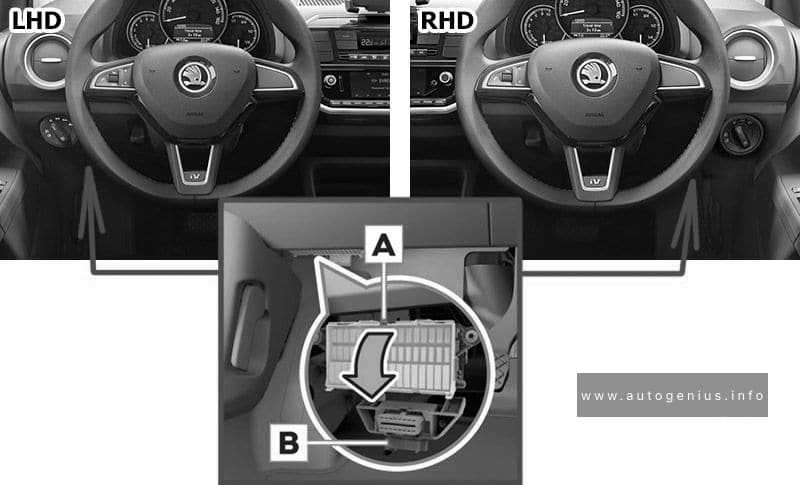
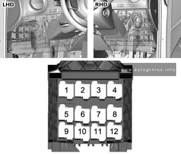
Passenger compartment fuse box
Fuse box location
The fuses are located underneath the steering wheel on the underside of the dash panel.
Skoda CITIGOe iV – fuse and relay box location – passenger compartment
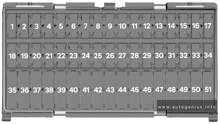
Fuse box diagram
Skoda CITIGOe iV – fuse and relay box diagram – passenger compartment
Assignment of the fuses below the instrument panel
№
Amps
Function/component
1
7.5A
Dash panel insert
Engine control unit
2
7.5A
High-voltage battery 1
Diagnostic connection
3
7.5A
Rear view camera
4
–
–
5
7.5A
Steering column electronics control unit
Onboard supply control unit
6
7.5A
Mirror adjustment switch
Headlight range control regulator
Left headlight range control motor
Right headlight range control motor
7
10A
Power and control electronics for electric drive
8
7.5A
Selector lever
Brake servo control unit
Charge voltage control unit for high-voltage battery
Power and control electronics for electric drive
9
7.5A
Front passenger side airbag deactivated warning lamp
Airbag control unit
10
7.5A
Control unit for the parking aid
11
7.5A
Front camera for driver assistance systems
12
–
–
13
–
–
14
15A
Rear window wiper motor
15
10A
Light switch
16
7.5A
Terminal 15 voltage supply relay
Power-assisted steering control unit
17
15A
Steering column electronics control unit
18
15A
Charging unit 1 for high-voltage battery
19
–
–
20
7.5A
ABS control unit
Steering column electronics control unit
21
–
–
22
–
–
23
7.5A
Engine control unit
24
15A
Steering column electronics control unit
Headlight flasher switch
25
10A
Windscreen and rear window washer pump
26
7.5A
Main relay
Dash panel insert
27
7.5A
Onboard supply control unit
Interior light
28
7.5A
Diagnostic connection
29
7.5A
Onboard supply control unit
30
7.5A
Onboard supply control unit
Heated exterior mirror on driver side
Heated exterior mirror on passenger side
31
10A
Radiator fan
32
15A
Onboard supply control unit
Turn signal/brake light
33
–
–
34
–
–
35
–
–
36
20A
Cigarette lighter
37
15A
Engine sound generator control unit
38
20A
Radio
39
–
–
40
15A
Engine control unit
41
20A
Onboard supply control unit
Central locking
42
20A
Coolant pump for high-temperature circuit
Coolant circulation pump upstream of power and control electronics for electric drive
43
20A
Centre switch module in dash panel
Centre switch module 2 in dash panel
Heated front seats control unit
44
7.5A
High-voltage battery 1
45
10A
Light switch
46
30A
Onboard supply control unit
Heated rear window
47
30A
Front right window regulator switch
Operating unit for window lifter in driver door (RHD)
Driver side central locking lock unit
48
20A
Onboard supply control unit
High-frequency horn
Low frequency horn
49
30A
Onboard supply control unit
Wiper motor control unit
50
20A
Onboard supply control unit
Left tail light cluster
Left reversing light bulb
Right tail light cluster
Right reversing light bulb
51
30A
Operating unit for window regulator in driver door
Driver side central locking unit (RHD)
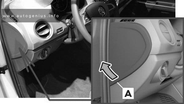
Fuses behind the side cover of the dash panel
Fuse box location
Skoda CITIGOe iV – fuse and relay box location – behind of the dash panel
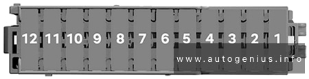
Fuse box diagram
Skoda CITIGOe iV – fuse and relay box diagram – behind of the dash panel
Assignment of the fuses in the instrument panel
№
Amps
Function/component
1
7.5A
Control unit for emergency call module and communication unit
2
30A
Brake system pressure accumulator
3
7.5A
Solenoid valve for ignition key withdrawal lock
4
20A
Blower relay
5
7.5A
Climatronic relay
6
10A
Emergency cut-out connection Maintenance connector for high-voltage system
7
7.5A
Climatronic control unit
8
7.5A
Selector lever
Rain and light sensor
Charge voltage control unit for high-voltage battery
9
15A
Onboard supply control unit
Low beam/daytime running lights/high beam
10
15A
Onboard supply control unit
Low beam/daytime running lights/high beam
11
30A
Heated windscreen relay
12
30A
Heated windscreen relay 2
Relay panel
Fuse box location and diagram
Skoda CITIGOe iV – fuse and relay box location – relay panel
Assignment of the fuses in the relay panel
№
Relay
1
Terminal 75 voltage supply relay 1
2
Terminal 15 voltage supply relay
3
Heated windscreen relay
4
Main relay
5
not assigned
6
Heated windscreen relay 2
7
Climatronic relay
8
not assigned
9
not assigned
10
Blower relay
11
not assigned
12
not assigned
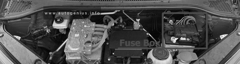
Engine Compartment Fuse Box
Fuse Box Location
Skoda CITIGOe iV – fuse and relay box location – engine compartment
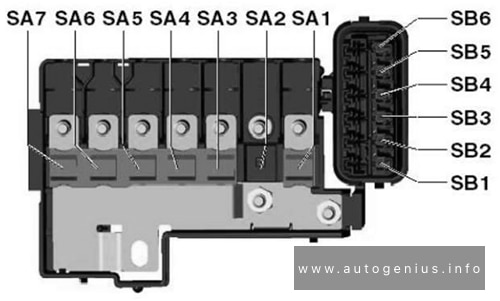
Fuse Box Diagram
Skoda CITIGOe iV – fuse and relay box diagram – engine compartment
Assignment of the fuses in the engine compartment
№
Amps
Function/component
SA1
250A
Power and control electronics for electric drive
SA2
–
–
SA3
150A
Fuse holder C (below the instrument panel)
Fuse holder D (at the end of the instrument panel)
Terminal 15 voltage supply relay
SA4
50A
Power-assisted steering control unit
SA5
40A
ABS control unit
SA6
40A
Radiator fan
SA7
50A
Brake servo control unit
SB1
30A
ABS/ESC control unit
SB2
7.5A
Brake servo control unit
SB3
7.5A
Ignition starter switch / Control lever under the steering whee
SB4
10A
ABS/ESC control unit
SB5
7.5A
Battery monitor control unit
Onboard supply control unit
SB6
30A
Ignition starter switch
WARNING: Terminal and harness assignments for individual connectors will vary depending on vehicle equipment level, model, and market.