BYD Tang EV (2022 – 2024) – fuse and relay box diagram
Year of production: 2022, 2023, 2024
This article provides fuse box diagrams for the BYD Tang EV models from 2022 and 2023. It also offers details on the location of the fuse panels within the vehicle, along with an explanation of each fuse’s assignment (fuse layout) and the relays.
Instrument panel fuse box
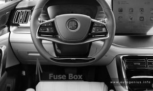
Fuse Box Location
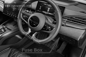
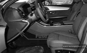
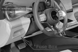
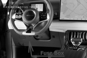
The dashboard panel fuses are located under the driver side of the dashboard.
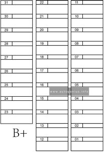
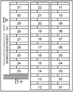
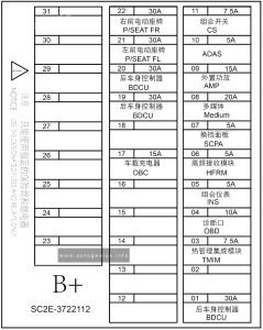
Fuse Box Diagram
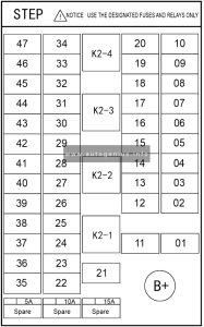
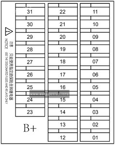
Assignment of the fuses in the instrument panel
| № | Amps | Function |
|---|---|---|
| 1 | – | – |
| 2 | 30A | BCM (Body Control Module) |
| 3 | 10A | A/C |
| 4 | 20A | Door Lock |
| 5 | 5A | Stop (Brake Light Switch) |
| 6 | 7.5A | Switch BAT |
| 7 | 10A | Door ECU |
| 8 | 5A | Meter (Cluster) |
| 9 | 20A | S/ROOF (Sun Roof Motor) |
| 10 | 5A | NFC |
| 11 | – | – |
| 12 | 10A | DLC (Data Link Connector) |
| 13 | 20A | Multimedia |
| 14 | – | – |
| 15 | – | – |
| 16 | 15A | STR Column (Steering Column) |
| 17 | 7.5A | DOME (Interior Lamp) |
| 18 | 30A | P/SEAT FR (Passenger Seat Front Right) |
| 19 | 30A | P/SEAT FL (Passenger Seat Front Left) |
| 20 | 20A | FL Door (Front Left Door Window Motor) |
| 21 | 40A | PWR Window (Power Window) |
| 22 | – | – |
| 23 | – | – |
| 24 | 5A | ABS / ESP / IPB |
| 25 | 5A | EPS (Electronic Power Steering) |
| 26 | 10A | SRS (Supplemental Restraint System) |
| 27 | 15A | SW Heater (Steering Wheel Heater) |
| 28 | 5A | Meter IG1 (Cluster IG1) |
| 29 | 5A | ADAS |
| 30 | 15A | P/SEAT ECU (Driver Seat ECU) |
| 31 | 7.5A | Shift |
| 32 | 20A | FR Door (Front Right Door Window Motor) |
| 33 | 20A | RL Door (Rear Left Door Window Motor) |
| 34 | 20A | RR Door (Rear Right Door Window Motor) |
| 35 | – | – |
| 36 | – | – |
| 37 | 7.5A | Switch IG1 |
| 38 | 5A | EPB ECU |
| 39 | 7.5A | PM 2.5 |
| 40 | – | – |
| 41 | – | – |
| 42 | – | – |
| 43 | – | – |
| 44 | – | – |
| 45 | 7.5A | USB |
| 46 | 15A | Backup PWR |
| 47 | – | – |
| K2-1 | IG1 Relay | |
| K2-2 | ACC Relay | |
| K2-3 | – | |
| K2-4 | – |
Engine Compartment Fuse Box
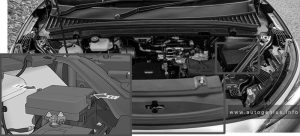
Fuse Box Location
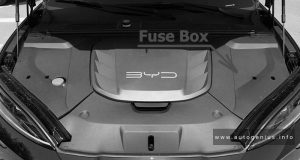
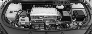
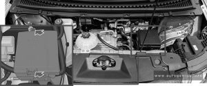
The front compartment fuse box is located on the left side of the front compartment.
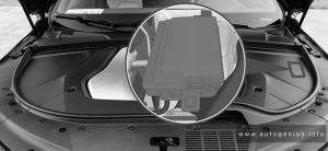
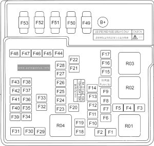
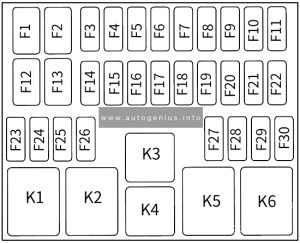
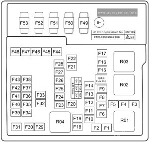
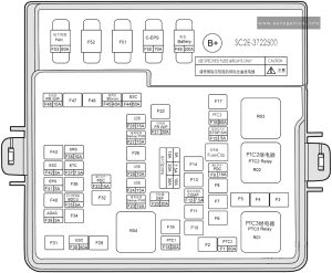
Fuse Box Diagram
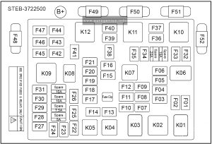
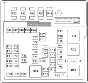
Assignment of the fuses in the engine compartment
| № | Amps | Function |
|---|---|---|
| F01 | – | – |
| F02 | – | – |
| F03 | – | – |
| F04 | – | – |
| F05 | – | – |
| F06 | – | – |
| F07 | 10A | ABTMP (Adaptive Battery Thermal Management Pump) |
| F08 | 10A | A/C Module |
| F09 | 7.5A | BMC (Battery Management Controller) |
| F10 | 5A | Battery Fleater |
| F11 | 10A | DMC (Drive Motor Controller) |
| F12 | 10A | DMC Pump |
| F13 | 60A | IPB (Integrated Power Brake) |
| F14 | 40A | Blower |
| F15 | – | – |
| F16 | – | – |
| F17 | 15A | Horn |
| F18 | – | – |
| F19 | – | – |
| F20 | 5A | CDU (Bi-Directional On-Board Charger and DC-DC and Power Distribution Unit Assembly) |
| F21 | 10A | FL_R (Front Lamp_Right) |
| F22 | – | – |
| F23 | – | – |
| F24 | – | – |
| F25 | 15A | WSFI (Windscreen Wash Motor) |
| F26 | – | – |
| F27 | – | – |
| F28 | – | – |
| F29 | – | – |
| F30 | – | – |
| F31 | – | – |
| F32 | – | – |
| F33 | – | – |
| F34 | – | – |
| F35 | 5A | Boost DC |
| F36 | – | – |
| F37 | – | – |
| F38 | 10A | FL_L (Front Lamp_Left) |
| F39 | 60A | IPB (Integrated Power Brake) |
| F40 | – | – |
| F41 | 20A | VTOV (Vehicle to Vehicle) |
| F42 | – | – |
| F43 | 25A | FR WIP (Front Wiper) |
| F44 | – | – |
| F45 | – | – |
| F46 | – | – |
| F47 | – | – |
| F48 | 200A | Battery |
| F49 | 60A | FAN |
| F50 | 100A | R-EPS (Rack-Electronic Power Steering) |
| F51 | 80A | IEC (Dashboard area fuse and relay box) |
| F52 | 80A | TEC (Trunk fuse and relay box) |
| K01 | – | |
| K02 | – | |
| K03 | IG4 relay | |
| K04 | – | |
| K05 | – | |
| K06 | – | |
| K07 | IG3 relay | |
| K08 | VTOV relay (Vehicle to Vehicle) | |
| K09 | – | |
| K10 | – | |
| K11 | – | |
| K12 | – |
Rear Compartment Fuse Box
Fuse Box Location
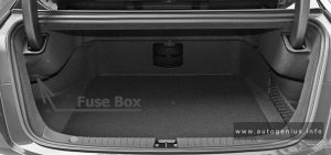
The rear compartment fuse box is located in the boot left facing assembly.
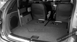
Fuse Box Diagram
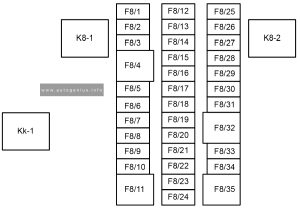
Assignment of the fuses in the rear compartment
| № | Amps | Function |
|---|---|---|
| F8/1 | – | – |
| F8/2 | – | – |
| F8/3 | 7.5A | MIR FHTR (Exterior RearView Mirror Fleater) |
| F8/4 | 40A | DEF (Defroster) |
| F8/5 | 30A | EPB (Electronic Parking Brake) |
| F8/6 | 30A | EPB (Electronic Parking Brake) |
| F8/7 | 20A | External amplifier |
| F8/8 | – | – |
| F8/9 | – | – |
| F8/10 | – | – |
| F8/11 | 20A | BD-ECU (Rear Flatch Controller) |
| F8/12 | 10A | ECU BAT (+30 for controller) |
| F8/13 | 5A | I-KEY (Intelligent key) |
| F8/14 | 10A | Charging Cap Lock |
| F8/15 | 5A | Charging Lamp |
| F8/16 | 10A | R-Tail (Rear Clearance Lamp / Charging State Indicator) |
| F8/17 | 7.5A | RR FOG/B-Lamp (Rear Right Fog lamp / Reversing Lamp) |
| F8/18 | 7.5A | DC Charging Lamp |
| F8/19 | 10A | R-HAZ (Rear Hazard Warning Lamp) |
| F8/20 | 20A | ACC |
| F8/21 | 15A | Toddler Lock |
| F8/22 | 15A | Backup PWR (Backup Power) |
| F8/23 | – | – |
| F8/24 | – | – |
| F8/25 | – | – |
| F8/26 | – | – |
| F8/27 | – | – |
| F8/28 | – | – |
| F8/29 | – | – |
| F8/30 | – | – |
| F8/31 | – | – |
| F8/32 | – | – |
| F8/33 | – | – |
| F8/34 | 15A | RR WIP (Rear Wiper) |
| F8/35 | 30A | R-Blower (Rear Blower) |
| Kk-1 | RR WIP Relay (Rear Wiper Relay) | |
| K8-1 | DEF Relay (Defroster Relay) | |
| K8-2 | Reserve Relay |
WARNING: Terminal and harness assignments for individual connectors will vary depending on vehicle equipment level, model, and market.

