KIA Telluride (2023 – 2024) – fuse and relay box diagram
Year of production: 2023, 2024
The Kia Telluride, a midsize SUV, has been available since 2020. This article provides fuse box diagrams for the 2023 and 2024 models, along with details on the locations of the fuse panels inside the vehicle and the functions of each fuse and relay.
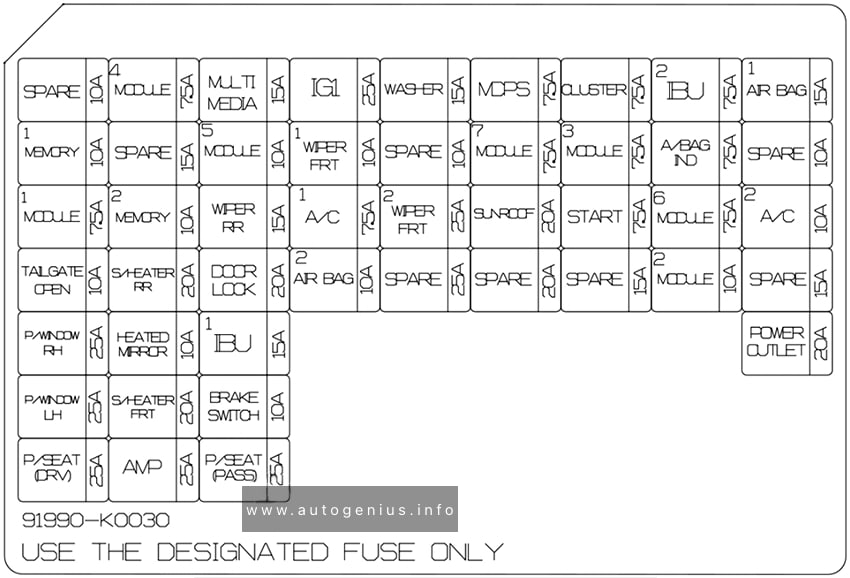
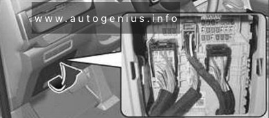
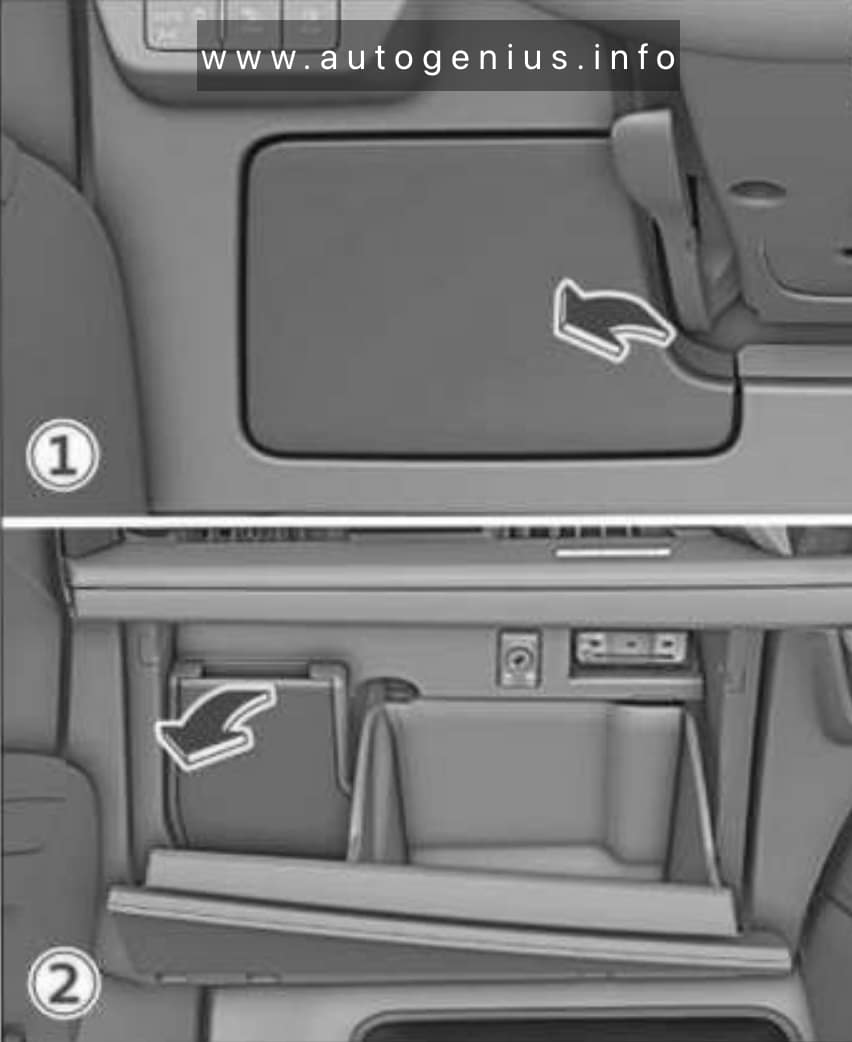
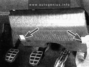
Passenger Compartment Fuse Box
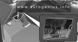
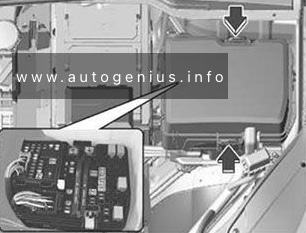
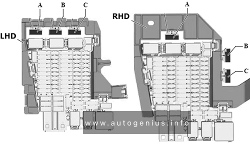
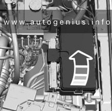
Fuse Box Location
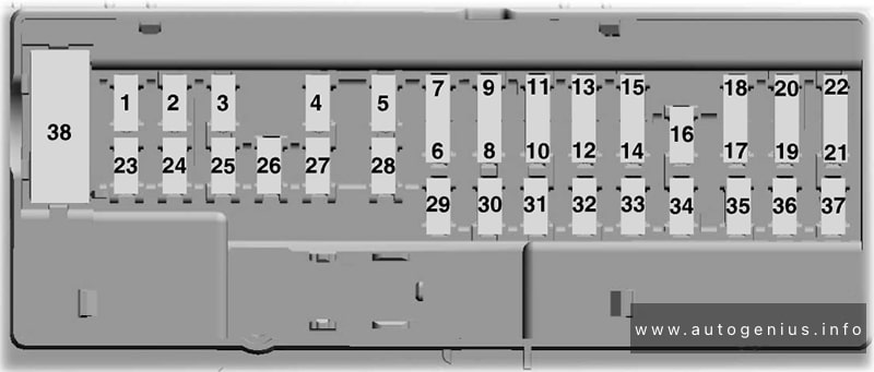
It is located behind the cover on the driver’s side of the instrument panel.
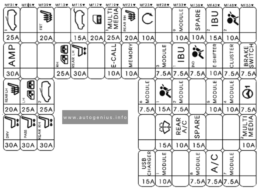
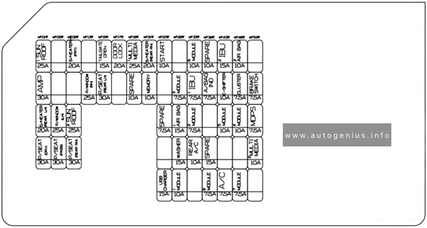
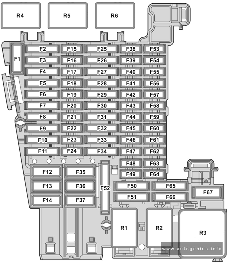
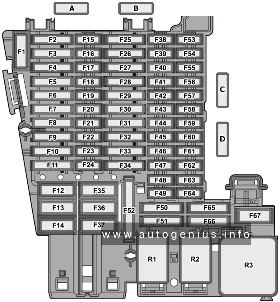
Fuse Box Diagram
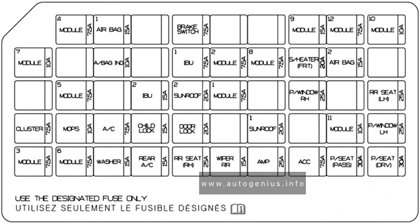
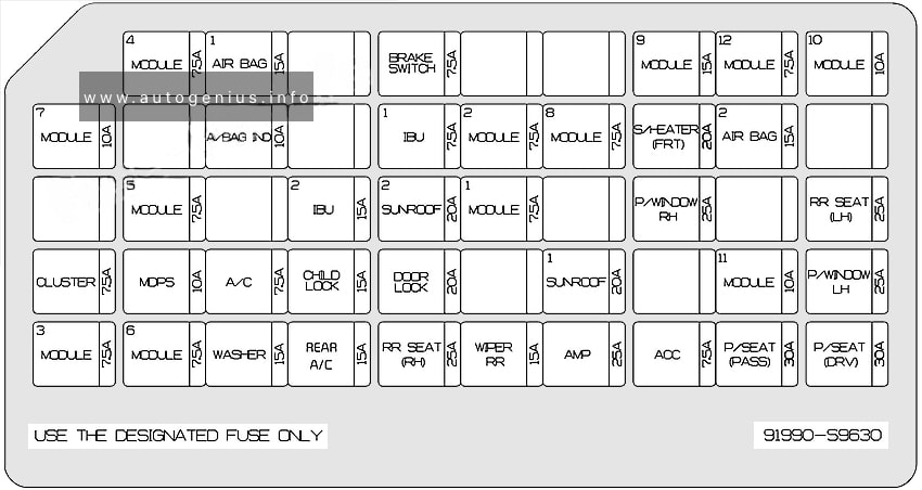
Assignment of the fuses in the Instrument panel
| Name | Amps | Protected component |
|---|---|---|
| MODULE 4 | 7.5A | ATM (Auto Transmission) Shift Lever Switch, Stop Lamp Switch, Driver Door Module |
| AIR BAG 1 | 15A | SRS (Supplemental Restraint System) Control Module, Passenger Occupant Detection Sensor |
| BRAKE SWITCH | 7.5A | IBU (Integrated Body Control Unit), Stop Lamp Switch |
| MODULE 9 | 15A | Front Air Conditioner Control Module, Low DC-DC Converter (Audio), Power Tail Gate Module, Driver IMS (Integrated memory system) Control Module, Driver Door Module, Driver/Passenger Power Outside Mirror, Rear Air Conditioner Control Module |
| MODULE 12 | 7.5A | Head-Up Display |
| MODULE 10 | 10A | Rear Corner Radar LH/RH, Electro Chromic Mirror, Console Switch |
| AIR BAG IND | 10A | Front Air Conditioner Control Module, Instrument Cluster |
| IBU 1 | 7.5A | IBU (Integrated Body Control Unit) |
| MODULE 2 | 7.5A | 360° camera monitoring system Unit, AC Inverter Outlet, AC Inverter Unit, Front Air Ventilation Seat Control Module, Front Seat Warmer Control Module, 2ND Air Ventilation Seat Control Module LH/RH, 2ND Seat Warmer Control Module LH/RH |
| MODULE 8 | 7.5A | Hazard Switch, Rain Sensor, Driver/Passenger Smart Key Outside Handle, Mood Lamp Control Unit, Driver/Passenger Mood Lamp, Driver/Passenger Door Mood Lamp, Rear Door Mood Lamp LH/RH |
| S/HEATER (FRT) | 20A | Front Air Ventilation Control Module, Front Seat Warmer Control Module, Data Link Connector |
| AIR BAG 2 | 15A | SRS (Supplemental Restraint System) Control Module |
| MODULE 5 | 7.5A | Front View Camera, Crash Pad Switch, IBU (Integrated Body Control Unit), Front Radar, ATM (Auto Transmission) Shift Lever Indicator, 4WD ECM (Engine Control Module), Console Switch, Electronic Parking Brake Switch |
| IBU 2 | 15A | IBU (Integrated Body Control Unit) |
| SUNROOF 2 | 20A | Rear Sunroof Controller |
| MODULE 1 | 7.5A | IBU (Integrated Body Control Unit) |
| P/WINDOW RH | 25A | Passenger Safety Power Window Module, Rear Safety Power Window Module RH |
| RR SEAT (LH) | 25A | 2ND Air Ventilation Seat Control Module LH, 2ND Seat Warmer Control, Module LH, 2ND Seat LH Reclining Folding Actuator |
| CLUSTER | 7.5A | Instrument Cluster, Head-Up Display |
| MDPS | 10A | MDPS / EPS (Motor Driven Power Steering) Unit |
| A/C | 7.5A | Engine Room Junction Block (Blower FRT Relay, Blower RR Relay, PTC Heater 1/2 Relay), Front A/C Control Module, Rear A/C Control Module |
| CHILD LOCK | 15A | ICM (Integrated Circuit Module) Relay Box (Child Lock/Unlock Relay) |
| DOOR LOCK | 20A | Door Lock Relay, Door Unlock Relay, Tail Gate Relay, T/Turn Unlock Relay |
| SUNROOF 1 | 20A | Front Sunroof Controller |
| MODULE 11 | 10A | Rear Occupant Detection Sensor |
| P/WINDOW LH | 25A | Driver Safety Power Window Module, Rear Safety Power Window Module LH |
| MODULE 3 | 7.5A | IBU (Integrated Body Control Unit) |
| MODULE 6 | 7.5A | Audio, Audio/Video & Navigation Head Unit, Low DC-DC Converter (Audio/AMP (Amplifier)), Front Air Conditioner Control Module, Electro Chromic Mirror, Center fascia Keyboard, Driver/Passenger Seat Warmer Switch, Driver/Passenger Seat Warmer LIN Switch, Driver IMS (Integrated memory system) Control Module, Front Air Ventilation Control Module, Front Seat Warmer Control Module, 2ND Air Ventilation Seat Control Module LH/RH, 2ND Seat Warmer Control Module LH/RH |
| WASHER | 15A | Multifunction Switch, Front Washer Motor, Rear Washer Motor, Washer Level Sensor |
| RR SEAT (RH) | 25A | 2ND Air Ventilation Seat Control Module RH, 2ND Seat Warmer Control, Module RH, 2ND Seat RH Reclining Folding Actuator |
| WIPER RR | 15A | Rear Wiper Relay, Rear Wiper Motor |
| AMP | 25A | Low DC-DC Converter (AMP (Amplifier)) |
| ACC | 7.5A | IBU (Integrated Body Control Unit), Low DC-DC Converter (Audio/ AMP) |
| P/SEAT (PASS) | 30A | Passenger Seat Manual Switch |
| P/SEAT (DRV) | 30A | Driver IMS (Integrated memory system) Control Module, Driver Seat Manual Switch |
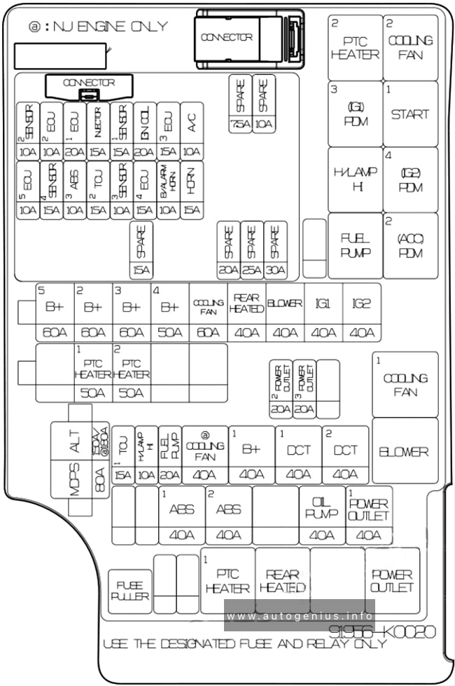
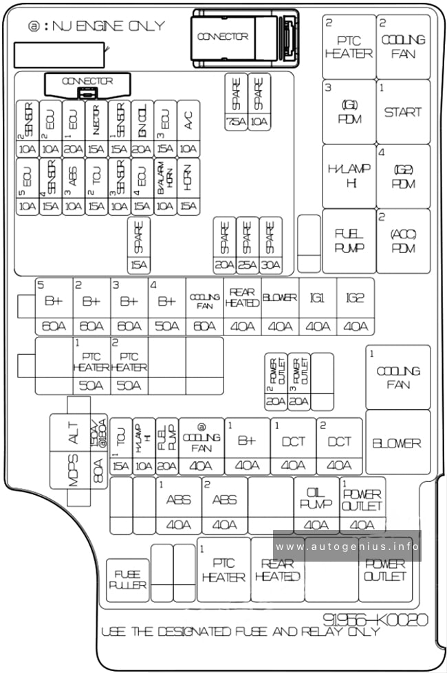
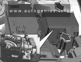
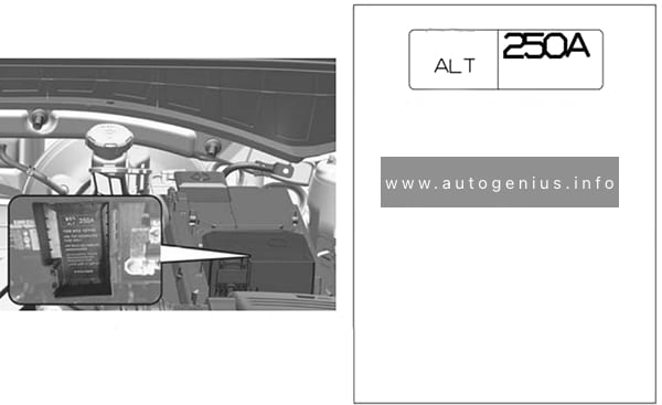
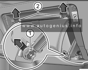
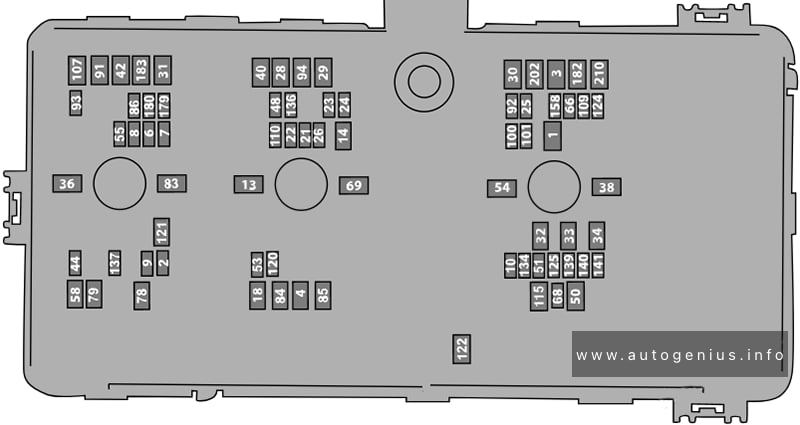
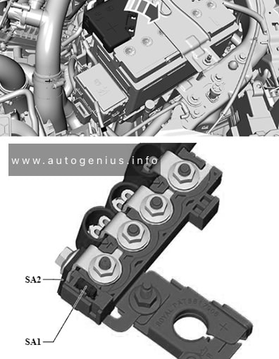
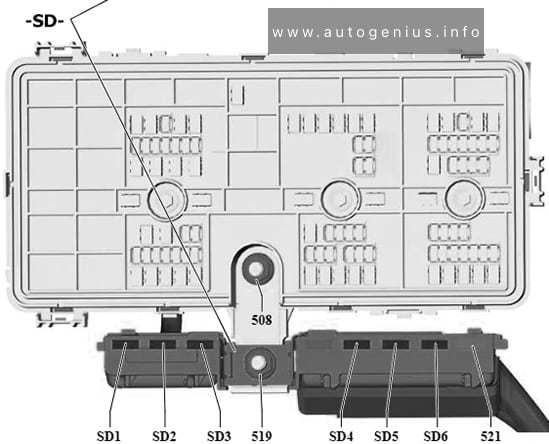
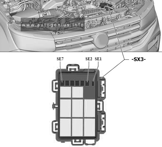
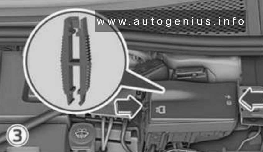
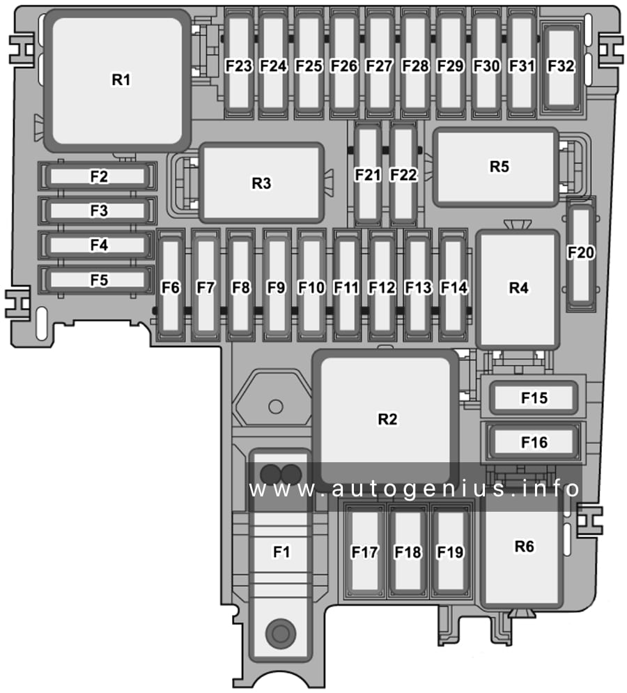
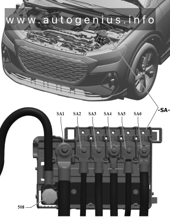
Engine Compartment Fuse Box
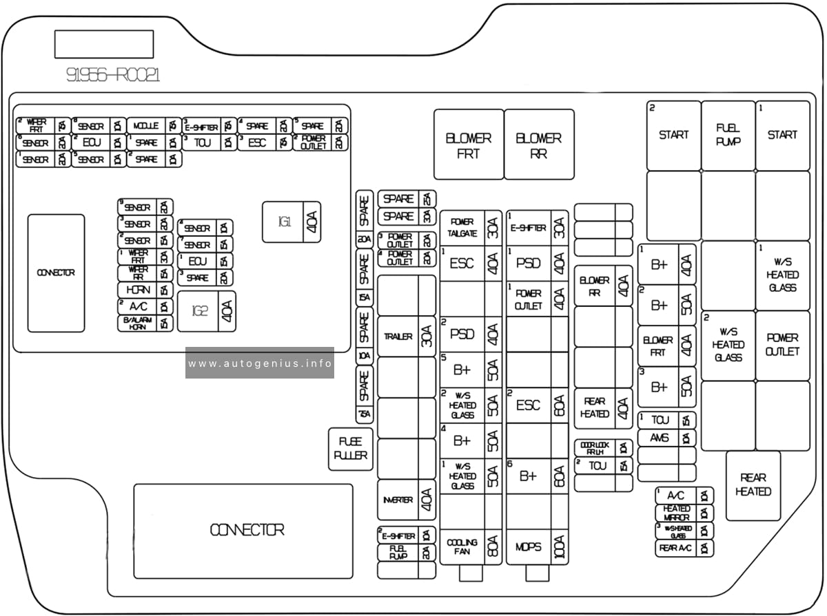
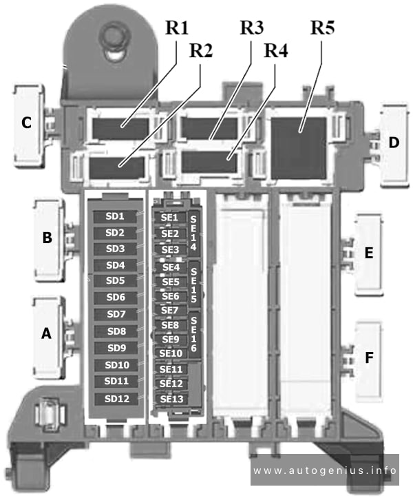
Fuse Box Diagram
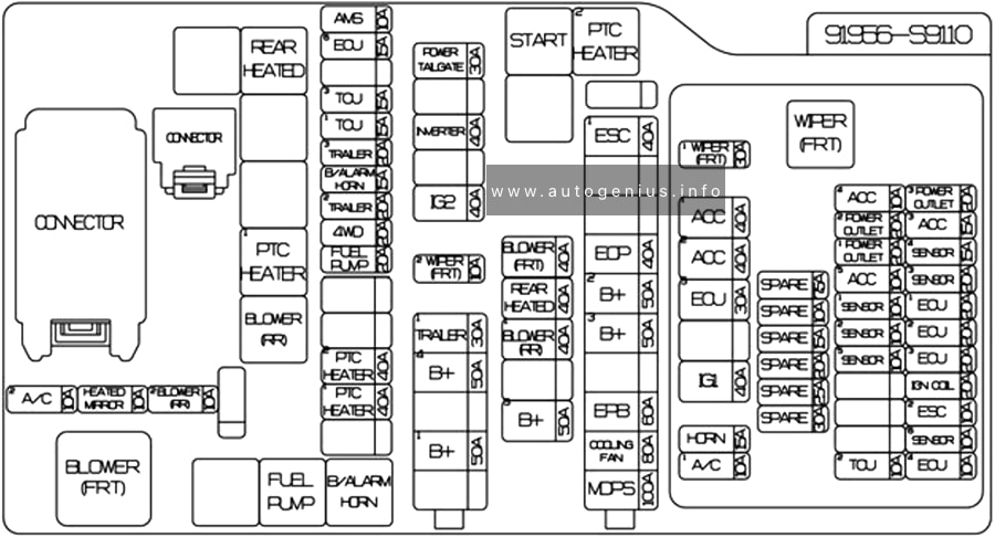
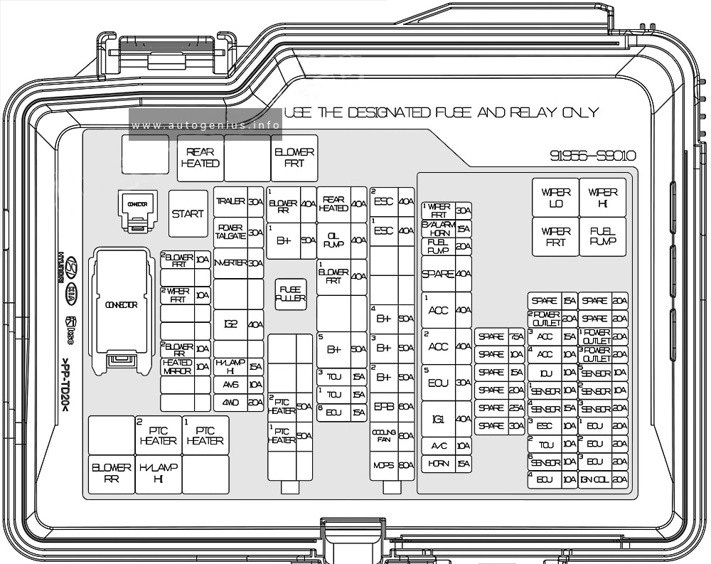
Assignment of the fuses in the engine compartment
| Name | Amps | Circuit Protected |
|---|---|---|
| MDPS | 80A | MDPS / EPS (Motor Driven Power Steering) Unit |
| COOLING FAN | 80A | Cooling Fan Controller |
| EPB | 60A | ESC (Electronic Stability Control) Module |
| B+2 | 50A | ICU Junction Block (IPS 8/IPS10/1 PS 11/IPS12/IPS13/IPS14/IPS15) |
| B+3 | 50A | ICU Junction Block (Fuse – P/WINDOW LH, RR SEAT (LH), P/SEAT (DRV), P/SEAT (PASS), MODULE 11) |
| B+4 | 50A | ICU Junction Block (Fuse – MODULE 8, S/HEATER (FRT), P/WINDOW RH, AMP, SUNROOF 1) |
| ESC 1 | 40A | ESC (Electronic Stability Control) Module |
| ESC 2 | 40A | ESC (Electronic Stability Control) Module |
| PTC HEATER 1 | 50A | PTC Heater 1 Relay |
| PTC HEATER 2 | 50A | PTC Heater 2 Relay |
| ECU 6 | 15A | ECM (Engine Control Module) |
| TCU 1 | 15A | TCM (Transmission Control Module) |
| TCU 3 | 15A | TCM (Transmission Control Module) |
| B+5 | 50A | ICU Junction Block (Fuse – DOOR LOCK, IBU (Integrated Body Control Unit) 1, IBU (Integrated Body Control Unit) 2, BRAKE SWITCH, CHILD LOCK, RR SEAT (RH), SUNROOF 2) |
| TRAILER 3 | 30A | Trailer Connector |
| BLOWER FRT1 | 40A | Blower FRT Relay |
| OIL PUMP | 40A | Electric Oil Pump Inverter |
| REAR HEATED | 40A | Rear Heated Relay |
| B+1 | 50A | ICU Junction Block (IPS 1/IPS 2/IPS 3/IPS 5/IPS 6/IPS 7, Long/Short Term Load Latch Relay) |
| BLOWER RR 1 | 40A | Blower RR Relay |
| 4WD | 20A | 4WD ECM (Engine Control Module) |
| AMS | 10A | Battery Sensor |
| H/LAMP HI | 15A | H/Lamp HI Relay |
| IG2 | 40A | Start Relay, PCB Block (IG2 Relay) |
| TRAILER 2 | 30A | Trailer Connector |
| INVERTER | 30A | AC Inverter Unit |
| POWER TAIL GATE | 30A | Power Tail Gate Module |
| TRAILER 1 | 30A | Trailer Connector |
| HEATED MIRROR | 10A | Driver/Passenger Power Outside Mirror, Front Air Conditioner Control Module |
| BLOWER RR 2 | 10A | Rear Air Conditioner Control Module |
| WIPER FRT 2 | 10A | IBU (Integrated Body Control Unit) |
| BLOWER FRT 2 | 10A | Front Air Conditioner Control Module |
| WIPER FRT 1 | 30A | Wiper FRT Relay |
| B/ALARM HORN | 15A | Burglar Alarm Horn Relay |
| FUEL PUMP | 20A | Fuel Pump Relay |
| ACC 1 | 40A | ACC 1 Relay |
| ACC 2 | 40A | ACC 2 Relay |
| ECU 5 | 30A | Engine Control Relay |
| IG1 | 40A | IG1 Relay |
| A/C | 10A | Air Conditioner Relay |
| HORN | 15A | Horn Relay |
| POWER OUTLET 2 | 20A | Front Power Outlet |
| ACC 3 | 15A | Rear USB Charger, Luggage USB Charger, Driver/Passenger Seat Cushion USB Charger |
| ACC 4 | 10A | Front USB Charger, Rear USB Charger RH |
| ICU | 10A | ICU Junction Block (Fuse – ACC) |
| SENSOR 1 | 10A | Fuel Pump Relay |
| SENSOR 4 | 15A | Canister Close Valve, Oxygen Sensor #1/#2/#3/#4 |
| ESC 3 | 10A | Data Link Connector, ESC (Electronic Stability Control) Module |
| TCU2 | 10A | TCM (Transmission Control Module), Transaxle Range Switch |
| SENSOR 6 | 10A | Electric Oil Pump Inverter |
| ECU 4 | 10A | ECM (Engine Control Module) |
| POWER OUTLET 1 | 20A | Luggage Power Outlet |
| POWER OUTLET 3 | 20A | Rear Power Outlet |
| SENSOR 5 | 10A | Oil Pump Solenoid |
| SENSOR 2 | 10A | A/C Relay, Purge Control Solenoid Valve, Oil Control Valve #1/#2/ #3/#4 (Intake/Exhaust), Variable Intake Solenoid Valve #1/#2, Electronic Thermostat |
| SENSOR 3 | 20A | Cooling Fan Controller |
| ECU 1 | 20A | ECM (Engine Control Module) |
| ECU 2 | 20A | ECM (Engine Control Module) |
| ECU 3 | 20A | ECM (Engine Control Module) |
| IGN COIL | 20A | Ignition Coil #1/#2/#3/#4/#5/#6 |
WARNING: Terminal and harness assignments for individual connectors will vary depending on vehicle equipment level, model, and market