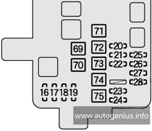
Volkswagen Transporter (T6; 2016 – 2019) – fuse and relay box diagram

Volkswagen Transporter (T6; 2016 – 2019) – fuse and relay box diagram

Year of production: 2016, 2017, 2018, 2019


This article focuses on the sixth-generation Volkswagen Transporter (T6), manufactured from 2015 to 2019. It includes fuse box diagrams for Volkswagen Transporter T6 models from 2016 to 2019, provides details on the location of the fuse panels within the vehicle, and explains the function and layout of each fuse and relay.

Fuse Box Location

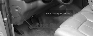
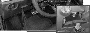
Volkswagen Transporter (T6; 2016 - 2019) - fuse box location
Volkswagen Transporter (T6; 2016 – 2019) – fuse box location
Component
1 Fuse holder K -SK-
2 Fuse holder C -SC-, Fuse holder D -SD- and Fuse holder F -SF-, in centre of dash panel
3 Hot air blower single fuse -S25- and Window regulator thermal fuse
4 Fuse 1 -S131-, fuse 2 -S132-, fuse 3 -S133-, fuse holder H -SH- (-SH1- to -SH30-) and fuse holder J -SJ-, under the left seat box
5 Fuse holder H -SH- (-SH35- to -SH50-), under the seat-box on the left
6 Fuse 31 in fuse holder H -SH31-, under the seat-box on the left
7 Fuse holder A -SA-, on left in engine compartment
8 Fuse holder B -SB-, on left in engine compartment

Fuse Holder K -SK-

Volkswagen Transporter (T6; 2016 - 2019) - fuse box diagram (fuse holder K -SK-)
Volkswagen Transporter (T6; 2016 – 2019) – fuse box diagram (fuse holder K -SK-)

Assignment of the fuses in the Fuse Holder K – SK-

Amps Function/component
1 not assigned
2/1 not assigned
2/2 3 A Multimedia system display unit 1 (only models with Rear Seat Entertainment)
2/3 3 A Multimedia system display unit 1 (only models with Rear Seat Entertainment)
3-8 not assigned


Single fuse -S25- and thermal fuse -S43-

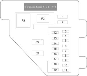
Volkswagen Transporter (T6; 2016 - 2019) - fuse box diagram - passenger compartment (single fuse -S25- and thermal fuse -S43-)
Volkswagen Transporter (T6; 2016 – 2019) – fuse box diagram – passenger compartment (single fuse -S25- and thermal fuse -S43-)
Amps Function/component
1 40 A Hot air blower single fuse -S25-:
Fresh air blower switch
Air conditioning system control unit
2 30 A Window regulator thermal fuse -S43-:
Driver door control unit
Front passenger door control unit


Fuse Holder A -SA-

Volkswagen Transporter (T6; 2016 - 2019) - fuse box diagram - engine compartment (fuse holder A -SA)
Volkswagen Transporter (T6; 2016 – 2019) – fuse box diagram – engine compartment (fuse holder A -SA)

Assignment of the fuses in the Fuse Holder A -SA-

Amps Function/component
1 225 A Alternator
2 125 A Fuse holder C -SC- (-SC1- to -SC17-)
3 50 A / 100 A Battery isolation relay
Second battery charging circuit relay
Fuses in fuse holder H: #25, 27
Left sliding door control unit
Right sliding door control unit
4 70 A Positive connection (30) in engine compartment wiring harness
5 60 A / 80 A ABS control unit
6 100 A Heated windscreen relay
Automatic glow period control unit
7 100 A Radiator fan control unit
8 50 A / 100 A Positive connection 1 (30) in interior wiring harness
Positive connection 2 (30) in interior wiring harness
Positive connection 3 (30), in main wiring harness
9 100 A Fuse holder C -SC- (-SC38- to -SC54-)

Fuse holder B -SB-

Fuse Box Location

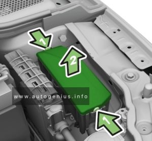
xVolkswagen Transporter (T6; 2016 - 2019) - fuse box location - engine compartment (fuse holder B -SB-)
xVolkswagen Transporter (T6; 2016 – 2019) – fuse box location – engine compartment (fuse holder B -SB-)


xVolkswagen Transporter (T6; 2016 - 2019) - fuse box location - engine compartment (fuse holder B -SB-)

  1. Open the bonnet;
  2. If necessary, remove the battery cover. Turn the quick release catches 90 degrees;
  3. Lift out the partition (1);
  4. Turn both quick release catches 90 degrees;
  5. Hold the fuse cover (3) at the front, and fold it upwards.

Fuse Box Diagram

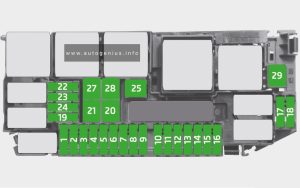
xVolkswagen Transporter (T6; 2016 - 2019) - fuse box diagram - engine compartment (fuse holder B -SB-)
xVolkswagen Transporter (T6; 2016 – 2019) – fuse box diagram – engine compartment (fuse holder B -SB-)

Assignment of the fuses in the Fuse Holder B

Amps Function/component
1 5 A Radiator fan control unit
2 5 A Additional coolant pump relay
Residual heat relay
Circulation pump
3 5 A Heater element for crankcase breather (petrol, diesel Euro 5)
4 30 A Voltage stabiliser
Control unit 1 for information electronics
Radio
Fuses on fuse holder C: #22, 58
5 15 A Selector lever
Mechatronic unit for dual clutch gearbox
Ignition key withdrawal lock solenoid
6 30 A ABS control unit
7 5 A Heater element for crankcase breather (diesel Euro 6)
8 30 A Heated windscreen
9 5 A Engine/motor control unit
10 10 A Charge pressure control solenoid valve (petrol)
Activated charcoal filter solenoid valve 1 (petrol)
Camshaft control valve 1 (petrol)
Turbocharger air recirculation valve (petrol)
Intake manifold flap valve (petrol)
10 15 A Charge pressure control solenoid valve (diesel)
Exhaust flap valve (diesel Euro 5)
Charge pressure control solenoid valve 2 (diesel Euro 6)
Intake manifold flap valve (diesel Euro 6)
Exhaust gas recirculation cooler changeover valve (diesel Euro 5)
Turbine changeover valve (diesel Euro 6)
11 not assigned
12 10 A Fuel pressure regulating valve (diesel Euro 5)
Fuel metering valve (diesel)
13 7.5 A Relay for reducing agent metering system (diesel Euro 6)
Reducing agent tank (diesel Euro 6)
Delivery unit for reducing agent metering system (diesel Euro 6)
14 5 A Fuel pump relay (diesel)
Electric fuel pump 2 relay (diesel Euro 5)
15 10 A Reversing light switch
16 5 A Brake light switch
17 5 A TCS and ESP button
Tyre Pressure Loss Indicator button
Hill descent control button
ABS control unit
18 5 A Power steering control unit
19 5 A Clutch pedal switch
Clutch position sender
Air mass meter (diesel)
20 5 A Engine/motor control unit
Air mass meter (petrol)
21 not assigned
22 not assigned
23 10 A Relay for reducing agent metering system
24 5 A Selector lever
Mechatronic unit for dual clutch gearbox
25 20 A Actuators 1-8 for camshaft adjustment
26 30 A Heated windscreen
27 10 A Continued coolant circulation pump (diesel Euro 5)
Charge air cooling pump (diesel Euro 6)
Pump for exhaust gas recirculation cooler (diesel Euro 6)
28 15 A Control unit for sensor electronics (diesel Euro 6)
Particulate sensor (diesel Euro 6)
Control unit for NOx sender (diesel Euro 6)
NOx sender (diesel Euro 6)
29 15 A Valve for oil pressure control (diesel Euro 6)
Coolant valve for cylinder head (diesel Euro 6)
Auxiliary pump for heating (diesel Euro 6)
Fuel shut-off valve switch-off relay (petrol)
Fuel pressure regulating valve (petrol)
30 20 A Fuel pump relay (diesel)
Fuel system pressurisation pump (diesel)
Electric fuel pump 2 relay (diesel Euro 5)
Supplementary fuel pump (diesel Euro 5)
Fuel pump control unit (petrol)
Fuel system pressurisation pump (petrol)
31 15 A Lambda probe
Lambda probe heater
Lambda probe after catalytic converter (petrol)
Lambda probe 1 heater after catalytic converter (petrol)
32 30 A Engine/motor control unit
Ignition coils 1-4 with output stage (petrol)
33 5 A Automatic glow period control unit (diesel)
Additional coolant pump relay (petrol, diesel Euro 5)
Fuel shut-off valve switch-off relay (petrol)
Coolant pump relay (petrol)
Continued coolant circulation pump (petrol)
34 5 A Onboard supply control unit
35 5 A Battery monitor control unit
36 30 A Starter inhibitor relay
Starter

Fuse holders C -SC-, D -SD- and F -SF-

Fuse Box Location

xVolkswagen Transporter (T6; 2016 - 2019) - fuse box location - passenger compartment (fuse holders C -SC-, D -SD- and F -SF-)
xVolkswagen Transporter (T6; 2016 – 2019) – fuse box location – passenger compartment (fuse holders C -SC-, D -SD- and F -SF-)
  1. Grasp into the recess (arrow), and carefully open the cover;
  2. Carefully pull the cover out of the mountings, and remove it.

Left-hand drive

xVolkswagen Transporter (T6; 2016 - 2019) - fuse box location - passenger compartment (fuse holders C -SC-, D -SD- and F -SF-) - left-hand drive
xVolkswagen Transporter (T6; 2016 – 2019) – fuse box location – passenger compartment (fuse holders C -SC-, D -SD- and F -SF-) – left-hand drive


Right-hand drive

xVolkswagen Transporter (T6; 2016 - 2019) - fuse box location - passenger compartment (fuse holders C -SC-, D -SD- and F -SF-) - right-hand drive
xVolkswagen Transporter (T6; 2016 – 2019) – fuse box location – passenger compartment (fuse holders C -SC-, D -SD- and F -SF-) – right-hand drive


Fuse Box Diagram

Left-hand drive

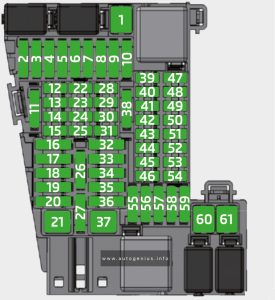
xVolkswagen Transporter (T6; 2016 - 2019) - fuse box diagram - passenger compartment (fuse holders C -SC-, D -SD- and F -SF-) - LHD
xVolkswagen Transporter (T6; 2016 – 2019) – fuse box diagram – passenger compartment (fuse holders C -SC-, D -SD- and F -SF-) – LHD


Right-hand drive

xVolkswagen Transporter (T6; 2016 - 2019) - fuse box diagram - passenger compartment (fuse holders C -SC-, D -SD- and F -SF-) - RHD
xVolkswagen Transporter (T6; 2016 – 2019) – fuse box diagram – passenger compartment (fuse holders C -SC-, D -SD- and F -SF-) – RHD

Assignment of the fuses and relays in the instrument panel fuse box (Fuse holders C, D and F)

Amps Function/component
C1 40 A Sender for front Bitron blower regulation
Fresh air blower
Auxiliary coolant heater relay
Fresh air blower switch
Air conditioning system control unit
C2 60 A X-contact relief relay
Positive connection (X), in interior wiring harness
C3 30 A Onboard supply control unit
C4 40 A Window regulator thermal fuse -S43-
Fuses on fuse holder C: #18, 22, 57, 58, 59
Fuses on fuse holder D: #1-7, 9
Fuses in fuse holder F: 1, 2, 3, 5, 6, 7, 9, 10
C5 7.5 A / 15 A Onboard supply control unit
C6 30 A Onboard supply control unit
C7 30 A Terminal 15 voltage supply relay
Positive connection 2 (15) in interior wiring harness
C8 5 A Light switch
C9 5 A Steering column combination switch
Headlight dipper and flasher switch
Onboard supply control unit
C10 30 A Control unit 1 for information electronics
Radio
C11 30 A Onboard supply control unit
C12 15 A Onboard supply control unit
C13 30 A Onboard supply control unit
C14 5 A Differential lock control unit
Isolation relay for powertrain CAN bus
16-pin connector (diagnostics)
C15 7.5 A Fresh air and air recirculation flap switch
Climatronic control unit
Air conditioning system control unit
C16 5 A Onboard supply control unit
C17 10 A Onboard supply control unit
C18 7.5 A USB hub
Two-way signal amplifier for mobile telephone/data services
Storage compartment with interface for mobile telephone
Reversing camera
C19 7.5 A Positive connection, in roof wiring harness
C20 7.5 A Positive connection 1 (30a) in main wiring harness
C21 10 A Onboard supply control unit
Relay 1 for ignition bypass
Interface for external use 6-pin connector
X-contact relief relay
C22 5 A Dash panel insert
C23 5 A Interface for external use 10-pin connector
Starter inhibitor relay
C23 30 A Starter
Starter inhibitor relay
Starter relay 1
Starter relay 2
C24 7.5 A Fresh air and air recirculation flap switch
Rear fresh air blower switch
Fresh air blower isolation relay
C25 10 A Rear window wiper motor
Rear left wing door window wiper motor
Rear right wing door window wiper motor
Left washer jet heater element
Right washer jet heater element
C26 5 A Terminal 75 voltage supply relay 1
Onboard supply control unit
Interface for external use 6-pin connector
C26 15 A Interface for external use 10-pin connector
C27 25 A Heated front seats control unit
C28 5 A Auxiliary coolant heater relay
C29 10 A Airbag control unit
Warning lamp for airbag deactivated on front passenger side
C30 10 A Mirror adjustment switch
Headlight range control regulator
Accident data recorder button
High-pressure sender
Air quality sensor
Oil level and oil temperature sender
Trailer detector control unit
Parking aid control unit
Headlight range control unit
Accident data memory
Front left headlight
Front right headlight
4-pin connector
10-pin connector
Diagnostic connection
Left headlight range control motor
Right headlight range control motor
Coolant shut-off valve relay
Climatronic coolant shut-off valve
Voltage supply relay 2
Parking aid control unit
C31 not assigned
C32 7.5 A Light switch
Operating and display unit for camping equipment
Accident data recorder button
Start/Stop operation button
Tachograph
Steering angle sender
Electronically controlled damping control unit
Multifunction steering wheel control unit
Onboard supply control unit
Accident data memory
Main beam assist control unit
Dash panel insert
Automatic anti-dazzle interior mirror
Headlight dipper and flasher switch
Onboard supply control unit
C33 10 A Rear differential lock switch
Vacuum switch for rear differential lock
All-wheel drive control unit
Differential lock control unit
Differential lock valve 1
Differential lock valve 2
C34 5 A Operating and display unit for camping equipment
Internet access control unit
10-pin connector
Interface for external use 10-pin connector
C35 10 A 10-pin connector
12-pin connector
C35 15 A Taximeter
Mirror taximeter
Taxi alarm remote control, control unit
C36 15 A Intermittent wiper switch
Rear wiper switch
Washer pump switch (automatic wash/wipe and headlight washer system)
Onboard supply control unit
Washer pump
Rear window wiper motor
Windscreen and rear window washer pump
Rear left wing door window wiper motor
Rear right wing door window wiper motor
C37 5 A Cruise control system switch
Cruise control system (CCS) SET button
Adaptive cruise control unit
Lane change assist control unit
Lane change assist control unit 2
C38 40 A Ignition/starter switch
C39 20 A Ignition/starter switch
C40 20 A 12 V socket 6
C40 30 A Auxiliary heater relay
Fresh air blower series resistor with overheating fuse
C41 30 A Onboard supply control unit
C42 25 A / 30 A Fresh air blower isolation relay
Rear fresh air blower switch
C42 30 A Rear blower regulation sender
Rear fresh air blower
C43 30 A Control unit for reducing agent heater
C44 15 A Rear lid control unit
C44 20 A Alarm horn
Onboard supply control unit
Rear lid control unit
Left sliding door control unit
Right sliding door control unit
C45 30 A Amplifier
C46 20 A Auxiliary heater control unit
C47 25 A Onboard supply control unit
C48 25 A Sliding sunroof adjustment control unit
C49 15 A Cigarette lighter
C50 25 A Headlight washer system relay
Headlight washer system pump
C51 5 A Steering angle sender
C52 5 A Interior monitor send and receive module 1
Interior monitor send and receive module 2
C53 5 A Rain and light sensor
C54 7.5 A Operating and display unit for camping equipment
Roof display unit
Remote control receiver for auxiliary heater
Remote control receiver for auxiliary coolant heater
Residual heat relay
Circulation pump
C55 5 A Operating and display unit for camping equipment
Onboard supply control unit
Roof hydraulics control unit
10-pin connector
Interface for external use 10-pin connector
C56 5 A Starter inhibitor relay
Engine/motor control unit
Interfacefor external use 10-pin connector
Interface for external use 10-pin connector
C57 5 A Operating and display unit for rear air conditioning system
C58 10 A Tachograph
C59 5 A Taximeter
Mirror taximeter
C59 10 A Red cross light switch
Red cross light bulb
C59 10 A Rotating light switch
Rotating light relay
Rotating light motor
D1 5 A Two-way radio button
Front interior light (door contact) button
Ignition bypass button
Button for daytime running light switch-off
D1 5 A Voltage supply relay 1
Voltage supply relay 2
Parking aid control unit
D1 15 A Interior light switch (taxi)
Taximeter
Taxi alarm remote control, control unit
Two-way radio
D1 20 A All-wheel drive control unit
D2 30 A Special vehicle control unit
D3 15 A Onboard charging unit
Internet access control unit
D3 15 A Alarm horn relay
Treble horn
D3 30 A Rear lid power opening control unit
D4 10 A Interior light relay
Switch and instrument illumination regulator
D4 15 A Alarm system relay 1
Onboard supply control unit
Front left headlight
D5 15 A Alarm system relay 1
Onboard supply control unit
Front right headlight
D5 15 A Electronically controlled damping control unit
D6 15 A Interface for external use 10-pin connector
D6 25 A 10-pin connector
D7 5 A Interface for external use 10-pin connector
D7 5 A 6-pin connector
D7 5 A Interior light switch (taxi)
Taxi sign switch
D8 5 A Accident data memory
6-pin connector
D8 15 A Interface for external use 10-pin connector
D9 10 A Relay 1 for ignition bypass
Relay 2 for ignition bypass
D9 25 A Interface for external use 6-pin connector
D10 5 A Interface for external use 10-pin connector
10-pin connector
D11 10 A Accident data memory
D11 15 A Accident data memory
10-pin connector
D11 15 A Interface for external use 10-pin connector
D11 15 A Accident data memory
Interface for external use 10-pin connector
D12 3 A 10-pin connector
Interface for external use 10-pin connector
F1 20 A All-wheel drive control unit
F2 5 A / 10 A Interior light relay
Switch and instrument illumination regulator
F3 30 A Driver seat adjustment control unit
Switch module for front passenger seat
Front passenger seat longitudinal adjustment motor
Front passenger seat front height adjustment motor
Front passenger seat rear height adjustment motor
Front passenger seat backrest adjustment motor
F4 5 A Emergency call module control unit and communication unit
F5 15 A Electronically controlled damping control unit
F6 30 A Driver seat adjustment control unit
Switch module for front passenger seat
Front passenger seat longitudinal adjustment motor
Front passenger seat front height adjustment motor
Front passenger seat rear height adjustment motor
Front passenger seat backrest adjustment motor
F7 5 A Accident data memory
F8 not assigned
F9 5 A Diagnosis wire relay
F9 5 A Voltage supply relay 1
Voltage supply relay 2
Parking aid control unit
F10 30 A Rear lid power opening control unit
F11 20 A 12 V socket 6
F12 not assigned
R1 X-contact relief relay
R2 Diagnosis wire relay
R2a Voltage supply relay 1
R2b Voltage supply relay 2
R3 Fresh air blower isolation relay
R4 Terminal 15 voltage supply relay

Fuse Holder H -SH-

Volkswagen Transporter (T6; 2016 - 2019) - fuse box diagram (fuse holder H -SH-)
Volkswagen Transporter (T6; 2016 – 2019) – fuse box diagram (fuse holder H -SH-)

Assignment of the fuses in the Fuse Holder H

Amps Function/component
1-7* Fuse 1 -S131- 10 A Right interior light
Rear right interior light
Kitchenette light 1
Kitchenette light 3
1-7* Fuse 2 -S132- 15 A 12 V socket
1-7* Fuse 3 -S133- 15 A 12 V socket 5
Kitchenette light 2
Front left reading light
4.1 Fuse 13 in fuse holder H -SH13- 7.5 A Climatronic control unit
4.1 Fuse 13 in fuse holder H -SH13- 30 A Auxiliary heater relay
Fresh air blower series resistor with overheating fuse
4.1 Fuse 13 in fuse holder H -SH13- 30 A Auxiliary heater relay
Fresh air blower series resistor with overheating fuse
4.2 Fuse 14 in fuse holder H -SH14- not assigned
4.3 Fuse 15 in fuse holder H -SH15- 30 A Trailer voltage supply relay
Trailer socket
5.1 Fuse 22 in fuse holder H -SH22- not assigned
5.2 Fuse 23 in fuse holder H -SH23- not assigned
5.3 Fuse 24 in fuse holder H -SH24- not assigned
6.1 Fuse 16 in fuse holder H -SH16- 30 A Onboard charging unit
Light control relay
Kitchenette light 4
6.2 Fuse 17 in fuse holder H -SH17- 30 A Roof hydraulics control unit
6.3 Fuse 18 in fuse holder H -SH18- 10 A Rear right reading light
Right interior light
Rear right interior light
Kitchenette light 1
Kitchenette light 2
Kitchenette light 3
7.1 Fuse 19 in fuse holder H -SH19- 10 A Refrigerator box
7.2 Fuse 20 in fuse holder H -SH20- 5 A Water pump switch for shower
Water pump switch
Coolant pump
7.3 Fuse 21 in fuse holder H -SH21- 5 A Operating and display unit for camping equipment
8.1 Fuse 1 in fuse holder H -SH1- 15 A 12 V socket 2
8.2 Fuse 2 in fuse holder H -SH2- 15 A Onboard charging unit
Map reading light bulb
12 V socket
12 V socket 3
8.3 Fuse 3 in fuse holder H -SH3- 10 A Switch-over relay 1 for roof ventilator
Switch for roof ventilator to ventilate load area
Switch for roof ventilator to extract air from load area
8.3 Fuse 3 in fuse holder H -SH3- 15 A 12 V socket 4
8.4 Fuse 4 in fuse holder H -SH4- 15 A Trailer detector control unit
8.5 Fuse 5 in fuse holder H -SH5- 20 A Trailer detector control unit
8.6 Fuse 6 in fuse holder H -SH6- 20 A Trailer detector control unit
8.7 Fuse 7 in fuse holder H -SH7- 15 A End position button for cupboard light
Cupboard light
Reading light relay
Left luggage compartment light
Rear lid light
Interior light
Front left reading light
Front right reading light
Rear lid light 2
Kitchen background lighting
8.7 Fuse 7 in fuse holder H -SH7- 10 A 10-pin connector
8.8 Fuse 8 in fuse holder H -SH8- not assigned
8.9 Fuse 9 in fuse holder H -SH9- 5 A Electric torch
8.10 Fuse 10 in fuse holder H -SH10- 15 A 12 V socket
8.10 Fuse 10 in fuse holder H -SH10- 30 A DC/AC converter with socket, 12 V – 230 V
DC/AC converter with socket, 12 V -115 V
8.11 Fuse 11 in fuse holder H -SH11- 20 A / 25 A Auxiliary heater control unit
8.12 Fuse 12 in fuse holder H -SH12- 15 A Driver seat lumbar support adjustment switch
Front passenger seat lumbar support adjustment switch
9-15* Fuse 25 in fuse holder H -SH25- 40 A Right sliding door control unit
9-15* Fuse 26 in fuse holder H -SH26- 80 A Second battery
9-15* Fuse 27 in fuse holder H -SH27- 40 A Left sliding door control unit
9-15* Fuse 28 in fuse holder H -SH28- 30 A Onboard charging unit
9-15* Fuse 29 in fuse holder H -SH29- 40 A Sender for front Bitron blower regulation
Fresh air blower
9-15* Fuse 30 in fuse holder H -SH30- 40 A Interface for external use 6-pin connector
R1 Switch-over relay 1 for roof ventilator
R2 Differential lock control unit
R3 Alarm system relay 1
R4 not assigned
R5 Trailer voltage supply relay
R6 Battery isolation relay
R7 Rotating light relay
Taxi alarm remote control, control unit
Terminal 75 voltage supply relay 1

*1-7 and 9-15: fuse location depends on equipment level.


Fuse 31 in fuse holder H -SH31-

Volkswagen Transporter (T6; 2016 - 2019) - fuse box diagram (fuse holder H -SH-) - fuse 31
Volkswagen Transporter (T6; 2016 – 2019) – fuse box diagram (fuse holder H -SH-) – fuse 31

Assignment of the fuses in the Fuse Holder H -SH31-

Amps Function/component
SH31 15 A 12 V socket 6


Relay carrier in engine compartment

Volkswagen Transporter (T6; 2016 - 2019) - fuse box diagram - engine compartment (relay carrier)
Volkswagen Transporter (T6; 2016 – 2019) – fuse box diagram – engine compartment (relay carrier)


Relay
1 Automatic glow period control unit (diesel)
1a Fuel shut-off valve switch-off relay (petrol)
1b Coolant pump relay (petrol)
2 Starter relay 2
3 Power steering control unit
4 Heated windscreen relay
5 Terminal 30 voltage supply relay
6 Starter inhibitor relay
7a Electric fuel pump 2 relay (diesel)
7b Coolant shut-off valve relay
8a Additional coolant pump relay
8b Fuel pump relay
9 Starter relay 1
10 not assigned
11 Relay for reducing agent metering system

Relay carrier behind dash panel

Volkswagen Transporter (T6; 2016 - 2019) - fuse box diagram - passenger compartment (relay carrier)
Volkswagen Transporter (T6; 2016 – 2019) – fuse box diagram – passenger compartment (relay carrier)
Relay
1 not assigned
2a Interior light relay
2b not assigned
3a Residual heat relay
3b Auxiliary heater relay
4 Headlight washer system relay
5 Isolation relay for powertrain CAN bus
6 Auxiliary coolant heater relay


WARNING: Terminal and harness assignments for individual connectors will vary depending on vehicle equipment level, model, and market.

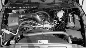
Chrysler Voyager (2020 – 2024) – fuse box diagram

Chrysler Voyager (2020 – 2024) – fuse box diagram


Year of production: 2020, 2021, 2022, 2023


This article covers the sixth-generation Chrysler Voyager, produced from 2020 to the present. It includes fuse box diagrams for Chrysler Voyager models from 2020 through 2024, provides details on the location of the fuse panels inside the vehicle, and explains the function of each fuse (fuse layout).

Engine compartment fuse box

Fuse Box Location

The Power Distribution Center (PDC) is located in the engine compartment near the battery. Remove the cover by unlatching the two locks located at each side of the PDC cover, avoid using screwdrivers or any other tool to remove the cover, since they may apply excessive force and result in a broken/damaged part.


Chrysler Voyager (2020 - 2024) - fuse box location - engine compartment
Chrysler Voyager (2020 – 2024) – fuse box location – engine compartment

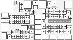
Fuse Box Diagram

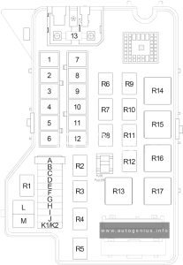
Chrysler Voyager (2020 - 2024) - fuse box diagram - engine compartment
Chrysler Voyager (2020 – 2024) – fuse box diagram – engine compartment


Assignment of the fuses in the PDC (2020-2024)

Amps Description
F06 Not Used
F07 25A Clear Ignition Coil / Fuel Injector
F08 Not Used
F09 25A Clear Amplifier / Active Noise Control
F10 Not Used
F11 Not Used
F12 5A Tan Battery Sensor (IBS)
F13 10A Red 2020-2021: ECM (ESS Only)
2022-2024: ECM (S)
F14 10A Red ECM
F15 40A Green CBC Feed #3 (Power Locks)
F16 20A Yellow ECM
F17 30A Pink Starter
F18 40A Green CBC Feed #4 (Exterior Lighting #1)
F19 25A Clear 2nd Row Folding Seats Solenoid LT
F20 10A Red A/C Compressor Clutch
F21 25A Clear 2nd Row Folding Seat Solenoid RT
F22 Not Used
F23 Not used
F24 20A Yellow RR Wiper
F25A 10A Red 2020-2021: Handsfree LT & RT RR Door Release Mod
F25B 10A Red 2020-2021: Active Grill Shutter / PWR Mirror
F25 10A Red 2022-2024: Hands-free Door Mod / Active Grill Shutter / PWR Mirror / VRM
F26 40A Green Front HVAC Blower Motor
F27 25A Clear RR Slide Door Module – RT
F28A 10A Red 2020-2021: Diagnostic Report
F28B 10A Red 2020-2021: USB + AUX Port / Video USB Port
F28 10A Red 2022-2024: Diagnostic Port / USB+ (IP) / Video USB Port / Overhead DVD Player (Aftermarket)
F29 Not Used
F30A 15A Blue 2020-2021: Media HUB 1&2
F30B 15A Blue 2020-2021: PWR Lumbar SW
F30 15A Blue 2022-2024: Media HUB / PWR Lumbar
F31 Not Used
F32 20A Blue ECM
F33 30A Pink Power Liftgate Module
F34 25A Clear RR Door Module – LT
F35 25A Clear Sunroof Control Module
F36 Not Used
F37 40A Green 2020-2021: CBC Feed #4 (Exterior Lighting #2)
2022-2024: CBC / Exterior Lights
F38 60A Yellow Vacuum Cleaner
F39 25A Clear Rear HVAC Blower Motor
F40 Not Used
F41 Not Used
F42 40A Green Folding Seat Module
F43 20A Yellow Fuel Pump Motor
F44 30A Pink 2020-2021: CBC Feed #1 (Interior Lights)
2022-2024: CBC / Interior Lights
F45 30A Pink Power Inverter
F46 30A Pink Driver Door Module
F47 30A Pink Passenger Door Module
F48 Not Used
F49 25A Clear RR Sliding Door Module – LT
F50 25A Clear RR Door Module – RT
F51 30A Pink Front Wiper
F52 30A Pink Brake Vacuum Pump
F53 Not Used
F54 40A Green ESP-ECU And Valves
F55A 15A Blue 2020-2021: Radio Frequency HUB / Keyless Ignition System (KIN) / (Electronic Steering Lock-BUX ONLY)
F55B 15A Blue 2020-2021: DVD / Video Routing Module (VRM
F55 15A Blue 2022-2024: RF HUB/ KIN / ESL / DVD
F56A 10A Red 2020-2021: Front and Rear HVAC Control Module / Occupant Classification Module (OCM) / Electronic Steering Lock (ESL)
F56B 10A Red 2020-2021: ESP/ESC
F56 10A Red 2022-2024: Front & Rear HVAC Control / OCM / ESL / ESP / ESC
F57 Not Used
F58 10A Red Drive Train Control Mod / Power Transfer Unit – If Equipped
F59 30A Pink Trailer Tow Receptacle – If Equipped
F60 20A Yellow Rear Cargo APO
F61 20A Yellow Trailer Tow Right Stop/Turn – If Equipped
F62 Not Used
F63 20A Yellow Trailer Tow Left Stop/Turn – If Equipped
F64 15A Blue RT HID Headlamp
F65 Not Used
F66 15A Blue 2020-2021: Instrument Panel Cluster (IPC) / SGW
2022-2024: Cluster
F67 10A Red Haptic Lane Feedback Module (HALF) / Parktronics System (PTS) / Drivers Assist System Module (DASM)
F68 Not Used
F69 Not Used
F70 Not Used
F71 20A Yellow Horn
F72 10A Red Heated Mirrors – If Equipped
F73 30A Pink Rear Defroster (EBL)
F74 20A Blue Trailer Tow Backup
F75 5A Tan Overhead Console / RR ISC
F76 20A Yellow Uconnect / Center Display / Telematics
F77A 10A Red 2020-2021: RR Entertainment Screen 1 & 2 / Media HUB 1 & 2 / 3rd Row USB Charge 0nly / 2nd Row USB Charge Only / Vaccum Cleaner SW / 3rd Row Recline ST SW / LT & RT Stow N Go SW / LT & RT Sliding Door SW Backlight
F77B 10A Red 2020-2021: Rain Sensor / Sunroof / CRVMM
F77 10A Red 2022-2024: RR Entertainment / Media Hub / USB (S) / Rain Sensor / Sunroof / RR View Mirror / Overhead DVD Player / Int Monitoring Camera / Wireless Charging Pad
F78A 15A Blue 2020-2021: Transmission Control Module (TCM) / E-Shifter
F78B 15A Blue 2020-2021: Instrument Cluster
F78 15A Blue 2022-2024: TCM (ZF) / E-Shifter / Cluster
F79 10A Red 2020-2021: ICS / Front And Rear HVAC / SCCM / EPB
2022-2024: ICS / HVAC / EPB SW / Strg Column Cntrl
F80 Not Used
F81 Not Used
F82 Not Used
F83 20A Blue TT Park Lights – If Equipped
30A Pink Headlamp Washer Pump – If Equipped
F84 30A Pink Drive Train Control MOD – If Equipped
F85 20A Yellow Cigar Lighter
F86 Not Used
F87 Not Used
F88 20A Yellow Front Heated Seats
F89 20A Yellow Rear Heated Seats
F90 Not Used
F91 15A Blue Front Ventilated Seats / Heated Steering Wheel
F92 5A Tan Security Gateway
F93 Not Used
F94 40A Green ESC Motor Pump
F95A 10A Red USB Charge Port – ACC RUN
F95B 10A Red Selectable Fuse Location – USB IP (Direct) B+
F96 10A Red Occupant Restraint Controller (ORC) (Airbag)
F97 10A Red Occupant Restraint Controller (ORC) (Airbag)
F98 15A Blue Left HID Headlamp
F99 30A Pink Trailer Tow Module – If Equipped
F100A 10A Red 2020-2021: AHLM
F100B 10A Red 2020-2021: Rear Camera / LBSS / RBSS / CVPM / Humidity Sensor / ln Vehicle Temperature Sensor
F100 10A Red 2022-2024: Headlamp Level / RR Camera / Blindspot / Humidity Snsr / In Car Temp Snsr / Headlamp SW
CB1 25A Circuit Breaker Power Seats (Driver)
CB2 25A Circuit Breaker Power Seats (Pass)
30 Amp mini fuse is substituted for 25 Amp Circuit Breaker.
CB3 25A Circuit Breaker FRT PWR Window W/O Door Nodes + RR PWR Window Lockout


WARNING: Terminal and harness assignments for individual connectors will vary depending on vehicle equipment level, model, and market.
Volkswagen Transporter  (T5.1; 2010 – 2015) – fuse box diagram

Volkswagen Transporter  (T5.1; 2010 – 2015) – fuse box diagram


Year of production: 2010, 2011, 2012, 2013, 2014, 2015

This article covers the post-facelift fifth-generation Volkswagen Transporter (T5.1), manufactured from 2009 to 2015. It provides fuse box diagrams for Volkswagen Transporter T5.1 models from 2010 to 2015, along with details on the location of the fuse panels within the vehicle and the specific functions of each fuse (fuse layout).

Passenger Compartment Fuse Boxes

Fuse Box Location

Volkswagen Transporter (T5.1; 2010 - 2015) - fuse box location - passenger compartment
Volkswagen Transporter (T5.1; 2010 – 2015) – fuse box location – passenger compartment

Fuse Box Diagram (-SB-, -SC-)

Volkswagen Transporter (T5.1; 2010 - 2015) - fuse box diagram - passenger compartment (holder B and holder C)
Volkswagen Transporter (T5.1; 2010 – 2015) – fuse box diagram – passenger compartment (holder B and holder C)

Assignment of the fuses in the instrument panel (fuse holders C and B)

Amps Function/component
Fuse holder B
SB1 30A Terminal 15 voltage supply relay
SB2 5A Steering angle sender
SB3 10A Onboard supply control unit
SB4 5A Lane change assist control unit
Lane change assist control unit 2
SB5 15A Front left headlight
SB6 15A Front left headlight
SB7 15A Onboard supply control unit
SB8 15A Rear lid control unit -J605-
SB8 20A Alarm horn
Onboard supply control unit
Left sliding door control unit
Rear lid control unit
Right sliding door control unit
SB9 30A Onboard supply control unit
SB10 10A Intermittent wiper switch
Rear wiper switch
Intermittent wiper regulator
Washer pump switch (automatic wash/wipe and headlight washer system)
SB11 5A Number plate light
SB12 5A/30A Light switch
SB13 10A Airbag control unit
Front passenger side airbag deactivated warning lamp
SB14 25A Headlight dipper/flasher switch
SB15 7,5A Fresh air blower switch
Rear fresh air blower switch
Fresh air blower isolation relay
SB16 5A Onboard supply control unit
SB17 5A Rear fog light cut-out contact switch
Control unit in dash panel insert
Rear left fog light bulb
SB18 5A Control unit in dash panel insert
SB19 5A Operating and display unit for camping equipment
Onboard supply control unit
10-pin connector (only models with electric interface, for external use)
SB20 5A Diagnostic connection
Differential lock control unit (2011-2015)
SB21 5A Starter motor relay
Engine control unit
10-pin connector (only models with electric interface, for external use)
SB22 7,5A Light switch
Control unit in dash panel insert
Trailer detector control unit
Diagnostic connection
SB23 5A only models with electric interface, for external use:
Starter inhibitor relay
Onboard supply control unit
Engine control unit
10-pin connector
SB23 30A Starter
Starter inhibitor relay
Engine control unit
SB23 30A Starter inhibitor relay
Starter inhibitor relay, clutch pedal switch
SB24 5A Steering angle sender
SB25 7,5A Fresh air blower switch
Front blower Bitron regulation sender
Climatronic control unit
Air conditioning system control unit
SB26 30A Light switch
SB27 15A Front right headlight
SB28 15A Front right headlight
Control unit in dash panel insert
SB29
SB30 10A Left washer jet heater element
Right washer jet heater element
Rear window wiper motor
Rear right wing door window wiper motor
Rear left wing door window wiper motor
SB31 30A Onboard supply control unit
SB32 30A Onboard supply control unit
SB33 30A Radio
Control unit with display for radio and navigation system
SB34 25A Fuse 14 on fuse holder D
Fuse 17 on fuse holder D
Fuse 20 on fuse holder D
Fuse 24 on fuse holder D
SB35 5A Connection (58s), in roof wiring harness
Connection 1 (58d), in main wiring harness
Connection 2 (58d), in main wiring harness
Connection 3 (58d), in main wiring harness
Connection (58b), in driver side door wiring harness
SB36 25A Onboard supply control unit -J519- (T73a/13)
Fuse holder C
SC1 15A 10-pin connector
SC2 5A Interior monitor send and receive module 1
Interior monitor send and receive module 2
SC3 10A Red Cross light switch
Red Cross light warning lamp
SC3 15A Taxi meter
Taxi alarm remote control, control unit
SC4 10A Rear differential lock switch
Rear differential lock vacuum switch
Differential lock control unit
Four-wheel drive control unit
SC5 10A 6-pin connector
SC6 5A Oil level and oil temperature sender
SC7 10A Rotating light switch
SC7 30A Alarm system control unit
SC8 5A Parking aid control unit
SC9 5A Cruise control system switch
SC10 10A Switches and instruments illumination regulator
Headlight range control, control unit
Left headlight range control motor
Right headlight range control motor
SC11 15A Taxi meter
Taxi alarm system 2 control unit
Alarm system relay 1
Taxi alarm remote control, control unit
Two-way radio
SC12 5A Front left headlight
SC12 30A Onboard supply control unit
SC13 5A Drive train CAN bus isolation relay
SC14 5A Front right headlight
SC14 30A Onboard supply control unit
SC15 5A Mobile telephone operating electronics control unit
Voice amplification control unit
SC16 7,5A Interface for external multimedia unit
TV tuner
SC17 7,5A Onboard supply control unit
Interior light and luggage compartment light
Interior monitor deactivation switch
Automatic anti-dazzle interior mirror
SC18 5A Rear fresh air blower switch
SC18 5A Operating and display unit for rear Climatronic
Rear blower regulation sender
SC19 5A Automatic anti-dazzle interior mirror
SC20 10A Onboard supply control unit
SC21 5A Rain sensor
SC22 10A High pressure sender
Air quality sensor
Air conditioning system relay
Coolant shut-off valve relay
SC23 7,5A/10A Operating and display unit for camping equipment
Roof display unit
Residual heat relay
Remote control receiver for auxiliary heating
Remote control receiver for auxiliary coolant heater
SC24 7,5A Interior light and luggage compartment light
SC25 25A Heated front seats control unit
SC26 10A Tachograph
SC27 30A Terminal 15 voltage supply relay 2
SC28 5A Mirror adjustment switch
Mirror adjustment change-over switch
SC29 20A Heater control unit
SC30 5A Operating and display unit for camping equipment
SC30 5A Auxiliary coolant heater relay
SC31 5A Onboard supply charger unit
SC31 25A Sliding sunroof adjustment control unit
SC32 20A Headlight washer system relay
SC33 5A Tachograph
SC34 5A Airbag coil connector and return spring with slip ring
Multifunction steering wheel control unit
SC35 20A Onboard supply control unit
SC36 5A Operating and display unit for camping equipment
10-pin connector (only models with electric interface, for external us)
10-pin connector (for optimal equipment police (UF4/UF5) only)

Fuse Holder F

Volkswagen Transporter (T5.1; 2010 - 2015) - fuse box diagram - passenger compartment (holder F)
Volkswagen Transporter (T5.1; 2010 – 2015) – fuse box diagram – passenger compartment (holder F)

Assignment of the fuses in the instrument panel (fuse holders F)

Amps Function/component
1 5A 10-pin connector (models with electric interface, for external use)
6-pin connector
2 3A 10-pin connector (models with electric interface, for external use)
3 15A 10-pin connector (models with electric interface, for external use)
Accident data memory
3 5A Accident data memory
4 15A 10-pin connector (models with electric interface, for external use)
5 5A 10-pin connector (models with electric interface, for external use)
6 25A 6-pin connector (models with electric interface, for external use)
7 15A 12V socket
7 30A Transformer with socket, 12V – 230V/115V (camper only, not for camper Beach)
8 20A Heater control unit
8 25A Auxiliary heater control unit
9 25A Rear fresh air blower switch
Fresh air blower isolation relay
9 30A Rear fresh air blower switch
Fresh air blower isolation relay
Rear fresh air blower
10 15A/30A Fresh air blower switch
Auxiliary heater relay
Air conditioning system control unit
Fresh air blower series resistor with overheating fuse
11 15A Cigarette lighter
12 5A 10-pin connector (models with electric interface, for external use)
6-pin connector
Accident data memory
13
14
15
16 30A Onboard supply charger unit (camper only, not for camper Beach)
17 30A Roof hydraulics control unit (camper only, not for camper Beach)
18 10A Camper only, not for camper Beach:
Map reading light bulb
Rear right reading light
Right interior light
Luggage compartment light on left
Kitchenette light 1
Kitchenette light 2
Kitchenette light 3
19 10A Camper only, not for camper Beach:
Refrigerator box
20 5A Camper only, not for camper Beach:
Water pump switch
Water pump
21 5A Camper only, not for camper Beach:
Operating and display unit for camping equipment
22 15A 12V socket 2
23 15A 12V socket 3
24 10A Switch-over relay 1 for roof ventilator
Switch-over relay 2 for roof ventilator
Switch for roof ventilator to ventilate load area
Switch for roof ventilator to extract air from load area
24 15A 12V socket 4
25 15A Trailer detector control unit
26 20A Trailer detector control unit
27 20A Trailer detector control unit
28 7,5A Reversing camera system control unit
29
30 5A 2020: Voice amplification control unit
31
32
33 15A Driver seat lumbar support adjustment switch
34 40A Right sliding door control unit
35 80A Battery isolation relay
Second battery charging circuit relay
36 40A Left sliding door control unit
37 40A Fresh air blower (models with second battery)
38 40A 6-pin connector (models with electric interface, for external use)
39
Equipment camper Beach only:
S131 10A Right interior light
Rear right interior light
Kitchenette light 1
Kitchenette light 3
S132 10A/15A 12V socket
S133 15A 12V socket 5
Rear left reading light
Kitchenette light 2


Coupling station on left of seat box (10-pin)
Volkswagen Transporter (T5.1; 2010 - 2015) - fuse box diagram - passenger compartment (coupling station on left seat box (10-pin))
Volkswagen Transporter (T5.1; 2010 – 2015) – fuse box diagram – passenger compartment (coupling station on left seat box (10-pin))
Amps Function/component
A
B
C
D 30A Amplifier


Fuses on relay carrier 1 (cockpit) 8-pin

Under dash panel (center, under the fuses).

Volkswagen Transporter (T5.1; 2010 - 2015) - fuse box diagram - passenger compartment - additional fuses (carrier 1 - cockpit - 8-pin)

Amps Function/component
6 15A Alarm system control unit (Taxi)
6 10A Taxi alarm system 2 control unit (Taxi)
A
B 30A Driver door control unit
Front passenger door control unit
C


Fuses on relay carrier 2 (cockpit) 8-pin

Under dash panel (center, under the fuses).

Volkswagen Transporter (T5.1; 2010 - 2015) - fuse box diagram - passenger compartment - additional fuses (carrier 2 - cockpit - 8-pin)
Volkswagen Transporter (T5.1; 2010 – 2015) – fuse box diagram – passenger compartment – additional fuses (carrier 2- cockpit – 8-pin)
Amps Function/component
A
B
C 40A Fresh air blower switch
Air conditioning system control unit
C 40A Fresh air blower switch
Air conditioning system control unit
Auxiliary coolant heater relay (models with auxiliary heating)
Fresh air blower


Engine Compartment Fuse Boxes

Fuse Box Location

Volkswagen Transporter (T5.1; 2010 - 2015) - fuse box location - engine compartment
Volkswagen Transporter (T5.1; 2010 – 2015) – fuse box location – engine compartment

Fuse Box Diagram (-SD-)

Volkswagen Transporter (T5.1; 2010 - 2015) - fuse box diagram - engine compartment (holder D)
Volkswagen Transporter (T5.1; 2010 – 2015) – fuse box diagram – engine compartment (holder D)

Assignment of the fuses in the engine compartment (fuse holder D)

Amps Function/component
1 5A Radiator fan control unit
2 5A Additional coolant pump relay
Residual heat relay
Circulation pump
3 5A Heater element for crankcase breather
4 30A 2011-2015:
Voltage stabiliser (models with stop/start system)
Control unit with display for radio and navigation system (models with stop/start system)
Radio (models with stop/start system)
Fuse 18 on fuse holder B (models with stop/start system)
Fuse 15 on fuse holder C (models with stop/start system)
Fuse 16 on fuse holder C(models with stop/start system)
5 15A Mechatronic unit for dual clutch gearbox
Selector lever lock solenoid
Selector lever
6 30A ABS control unit
7 7,5A Washer pump
Windscreen and rear window washer pump
8
9 5A Engine control unit
10 5A Secondary air pump relay (for engine code AXA)
Activated charcoal filter system solenoid valve 1 (for engine code AXA)
10 15A Charge pressure control solenoid valve (for engine codes CAAA, CAAB, CAAC, CAAD, CAAE, CCHA, CCHB, CFCA)
Exhaust flap valve (for engine code CFCA)
Exhaust gas recirculation cooler change-over valve (for engine codes CAAA, CAAB, CAAC, CAAD, CAAE, CCHA, CCHB, CFCA)
10 10A Charge pressure control solenoid valve (for engine code CJKA)
Activated charcoal filter system solenoid valve 1 (for engine code CJKA)
Inlet camshaft control valve 1 (for engine code CJKA)
Turbocharger air recirculation valve (for engine code CJKA)
Intake manifold flap valve (for engine code CJKA)
11 30A Headlight dipper/flasher switch
Headlight main beam relay
12 10A Fuel pressure regulating valve (for engine codes CAAA, CAAB, CAAC, CAAD, CAAE, CCHA, CCHB, CFCA)
Fuel metering valve (for engine codes CAAA, CAAB, CAAC, CAAD, CAAE, CCHA, CCHB, CFCA)
13 10A 2010-2011: Left gas discharge light control unit
14 5A Fuel pump relay (for engine codes CAAA, CAAB, CAAC, CAAD, CAAE, CCHA, CCHB, AXA, CFCA)
Electric fuel pump 2 relay (for engine codes CAAA, CAAB, CAAC, CAAD, CAAE, CCHA, CCHB, CFCA)
15 10A Reversing light switch
16 5A Brake light switch
Air mass meter (for engine code AXA)
17 5A TCS and ESP button
Tyre pressure monitor display button
ABS control unit
18 5A Power steering control unit
19 5A Clutch pedal switch
Clutch position sender
Air mass meter (for engine codes CAAA, CAAB, CAAC, CAAD, CAAE, CCHA, CCHB, CFCA)
20 5A Engine control unit
Air mass meter (for engine code CJKA)
21 5A Exhaust gas recirculation valve (for engine code AXA)
22 10A Injector, cylinder 1~4 (for engine code AXA)
23 10A 2010-2011: Right gas discharge light control unit
24 5A Mechatronic unit for dual clutch gearbox
Selector lever
25 30A Engine control unit (for engine code AXA)
Ignition transformer (for engine code AXA)
25 20A Actuator 1~8 for camshaft adjustment (for engine code CJKA)
26 5A 2010-2011: Front left headlight
27 10A Continued coolant circulation pump (for engine codes CAAA, CAAB, CAAC, CAAD, CAAE, CCHA, CCHB, CFCA)
28 15A Treble tone horn (for models with taxi equipment)
29 5A 2010-2011: Front right headlight
30 20A Fuel pump relay (for engine codes CAAA, CAAB, CAAC, CAAD, CAAE, CCHA, CCHB, CFCA)
Fuel system pressurisation pump (for engine codes CAAA, CAAB, CAAC, CAAD, CAAE, CCHA, CCHB, CFCA)
Electric fuel pump 2 relay (for engine codes CAAA, CAAB, CAAC, CAAD, CAAE, CCHA, CCHB, CFCA)
Supplementary fuel pump (for engine codes CAAA, CAAB, CAAC, CAAD, CAAE, CCHA, CCHB, CFCA)
Fuel system pressurisation pump (for engine code AXA)
Fuel pump control unit (for engine code CJKA)
Fuel system pressurisation pump (for engine code CJKA)
31 15A Lambda probe heater
Lambda probe 1 heater after catalytic converter (for engine code AXA, CJKA)
32 5A Electric fuel pump 2 relay (for engine code AXA)
32 30A Engine control unit (for engine codes CAAA, CAAB, CAAC, CAAD, CAAE, CCHA, CCHB, CFCA)
32 30A Engine control unit (for engine code CJKA)
Ignition coil 1~4 with output stage (for engine code CJKA)
33 5A Automatic glow period control unit (for engine codes CAAA, CAAB, CAAC, CAAD, CAAE, CCHA, CCHB, CFCA)
Fuel shut-off valve switch-off relay (for engine code CJKA)
Additional coolant pump relay
Coolant pump relay (for engine code CJKA)
Continued coolant circulation pump (for engine code CJKA)
34 5A Onboard supply control unit
35 15A Fuel shut-off valve switch-off relay (for engine code CJKA)
Fuel pressure regulating valve (for engine code CJKA)
35 5A Battery monitor control unit (models with stop/start system)
36 30A Starter (models without stop/start system)
Starter inhibitor relay (models without stop/start system)
36 5A Data bus diagnostic interface (models with stop/start system)


High power fuses (-SA-)

Volkswagen Transporter (T5.1; 2010 - 2015) - fuse box diagram - engine compartment (High power fuses (-SA-))
Volkswagen Transporter (T5.1; 2010 – 2015) – fuse box diagram – engine compartment (High power fuses (-SA-))
Volkswagen Transporter (T5.1; 2010 - 2015) - fuse box diagram - engine compartment (High power fuses (-SA-))
Volkswagen Transporter (T5.1; 2010 – 2015) – fuse box diagram – engine compartment (High power fuses (-SA-))


Amps Function/component
1 175A/225A Alternator
2 125A X-contact relief relay
Positive connection 2 (30), in main wiring harness
Positive connection 5 (30), in main wiring harness
Positive connection 6 (30), in main wiring harness
Positive connection 7 (30), in main wiring harness
Positive connection 8 (30), in main wiring harness
Positive connection 9 (30), in main wiring harness
Fuse 9 on fuse holder B
Fuse 14 on fuse holder B
3 50A/100A Second battery charging circuit relay
Positive connection 14 (30), in main wiring harness
Positive connection 15 (30), in main wiring harness
4 70A Positive connection (30), in engine compartment wiring harness
5 50A ABS control unit fuse 1
Fuse 6 on fuse holder D
6 50A/60A Automatic glow period control unit
Secondary air pump relay
7 100A Radiator fan control unit
8 40A/50A/100A Positive connection 1 (30), in interior wiring harness
Positive connection 2 (30), in interior wiring harness
Fuse 9 on fuse holder F
Fuse 14 on fuse holder F
Fuse 22 on fuse holder F
Fuse 23 on fuse holder F
Fuse 24 on fuse holder F
9 100A Positive connection (30), in main wiring harness
Positive connection 3 (30), in main wiring harness


Relay carrier electronics box (8-pin)
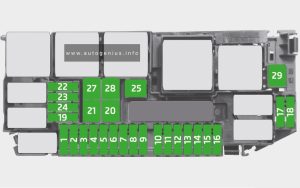
Volkswagen Transporter (T5.1; 2010 - 2015) - fuse box diagram - engine compartment - Relay carrier electronics box (8-pin)
Volkswagen Transporter (T5.1; 2010 – 2015) – fuse box diagram – engine compartment – Relay carrier electronics box (8-pin)
Amps Function/component
A
B 40A ABS control unit

WARNING: Terminal and harness assignments for individual connectors will vary depending on vehicle equipment level, model, and market.
Volkswagen Multivan (T6.1; 2019 – 2021) – fuse and relay box diagram

Volkswagen Multivan (T6.1; 2019 – 2021) – fuse and relay box diagram

Year of production: 2019, 2020, 2021


The Volkswagen Caravelle and Multivan are nearly identical both technically and externally, with the primary difference being in the interior trim and panels. Both models are built on the same platform as the VW Transporter and serve as its passenger variants. This article focuses on the seventh-generation Volkswagen Multivan (T7), produced from 2022 to 2024, and the facelifted sixth-generation Volkswagen Transporter/Multivan (T6.1), produced from 2019 to 2021. Here, you’ll find information about the location of the fuse panels and learn about the function and layout of each fuse and relay.


Fuse Holder A

Volkswagen Multivan (T6.1; 2021 - 2021) - fuse box diagram - fuse-holder A
Volkswagen Multivan (T6.1; 2019 – 2021) – fuse and relay box diagram – fuse-
holder A

Assignment of the fuses in the Fuse Holder A

Amps Function/component
SA1 225A Alternator with voltage regulator -CX1- (For models with an alternator with voltage regulator -CX1- (140A/180A) and without a second battery)
SA2 125A X-contact relay -J18-
– Fuses on fuse holder C: 55, 56, 57, 61
Terminal 15 voltage supply relay -J329-
– Fuses on fuse holder C: 9, 10, 39, 40, 42, 43, 44, 46
Fuses on fuse holder C: 1, 28, 29, 30, 31, 32, 33, 34, 35, 36, 37, 53, 60, 61
SA3 100A Fuses in fuse holder H: 1, 2, 3, 5, 6, 7, 8, 9, 10, 11, 12, 17, 18, 19, 20, 25, 26, 27, 28
SA4 80A Main relay-J271- :
– Fuses on fuse holder B: 1, 7, 10, 12, 14, 16, 19, 21, 23, 25, 27, 28, 29, 31, 32, 33
Fuses on fuse holder B: 2, 4, 5, 6, 9, 11, 13, 18, 30, 34
SA5 60A ABS control unit -J104- :
SA6 125A Power steering control unit -J500- :
SA7 100A Radiator fan -VX57- (For models with an alternator with voltage regulator -CX1- (140A/180A) and without a second battery)
Fuse 1 on fuse holder M -SM1- (For models with an alternator with voltage regulator -CX1- (140A/180A) and without a second battery)
SA8 100A Automatic glow period control unit -J179- (For models with an alternator with voltage regulator -CX1- (140A/180A) and without a second battery)
Heated windscreen relay -J47- (For models with an alternator with voltage regulator -CX1- (140A/180A) and without a second battery)
– Fuses on fuse holder B: 8, 26
SA9 125A Rear left turn signal additional relay -J420-
– Left roof mounted turn signal bulb -M23-
Rear right turn signal additional relay -J421-
– Right roof mounted turn signal bulb -M24-
Fuses on fuse holder C: 2, 3, 4, 5, 6, 7, 8, 11, 12, 13, 14, 15, 16, 17, 18, 19, 20, 21, 22, 23, 24, 25, 26, 27, 38, 47, 48, 50, 51, 52, 54, 58
SA10 Connection for battery -A-

Fuse Holder B

Fuse Box Location

Volkswagen Multivan (T6.1; 2021 - 2021) - fuse box location - fuse holder B
Volkswagen Multivan (T6.1; 2019 – 2021) – fuse and relay box location – fuse holder B


Fuse box diagram

Volkswagen Multivan (T6.1; 2019 - 2021) - fuse box diagram - fuse holder B
Volkswagen Multivan (T6.1; 2019 – 2021) – fuse and relay box diagram – fuse holder B

Assignment of the fuses in the Fuse Holder B

Amps Function/component
SB1 5A Radiator fan -VX57-
SB2 30A ABS control unit -J104-
SB3
SB4 10A Brake light additional relay -J419-
– High-level brake light bulb -M25-
SB5 10A Selector lever sensors control unit -J587-
Mechatronic unit for dual clutch gearbox -J743-
Ignition key withdrawal lock solenoid -N376-
SB6 10A ABS control unit -J104-
SB7 5A Heater element for crankcase breather -N79-
SB8 30A Heated windscreen -Z2-
SB9 5A Engine control unit -J623-
15A Engine control unit -J623-
SB10 10A Charge pressure control solenoid valve -N75-
Charge pressure control solenoid valve 2 -N274-
Intake manifold flap valve -N316-
Turbine changeover valve -N529-
10A Charge pressure control solenoid valve 2 -N274-
Solenoid for coolant circuit -N492-
Turbine changeover valve -N529-
SB11 10A Magnetic clutch relay -J44-
– Air conditioner compressor -VX81 –
SB12 10A Fuel pressure regulating valve -N276-
10A Fuel metering valve -N290-
SB13 10A Relay for reducing agent metering system -J963-
– Delivery unit for reducing agent metering system -GX19-
– Reducing agent tank -VX85-
SB14 5A Fuel pump relay -J17-
– Fuel delivery unit -GX1-
30A Fuel pump control unit -J538-
– Fuel delivery unit -GX1-
SB15 5A Reversing light switch -F4-
SB16 5A Brake light switch -F-
SB17 5A Centre switch module 3 in dash panel -EX48-
SB18 5A Heated windscreen relay -J47-
SB19 5A Air mass measurement module -GX35-
Clutch position sender-G476-
5A Clutch position sender -G476-
SB20 5A Engine/motor control unit -J623-
SB21 5A Reducing agent tank -VX85-
Control unit for reducing agent heater -J891 –
SB22 10A Auxiliary coolant heater relay -J493- (up to June 2021)
– Heater coolant shut-off valve -N279- (up to June 2021)
Auxiliary coolant heater coolant circuit valve relay -J575- (up to June 2021)
– Heater coolant shut-off valve -N279- (up to June 2021)
SB23 10A Relay for reducing agent metering system -J963-
SB24 5A Selector lever sensors control unit -J587-
Mechatronic unit for dual clutch gearbox -J743-
SB25 5A Oil level and oil temperature sender -G266-
SB26 30A Heated windscreen -Z2-
SB27 10A Charge air cooling pump -V188-
Pump for exhaust gas recirculation cooler -V400-
SB28 15A Control unit for NOx sender -GX30-
Control unit 2 for NOx sender -GX46-
Control unit 3 for NOx sender -GX50-
Control unit 1 for particulate sensor-GX52-
SB29 5A Valve for oil pressure control -N428-
Auxiliary pump for heating -V488-
15A Valve for oil pressure control -N428-
Charge air cooling pump -V188-
Pump for exhaust gas recirculation cooler -V400-
Auxiliary pump for heating -V488-
SB30 20A Fuel pump relay -J17-
– Fuel delivery unit -GX1-
SB31 15A Lambda probe 1 before catalytic converter -GX10-
SB32 30A Engine/motor control unit -J623-
SB33 5A Automatic glow period control unit -J179-
SB34 5A Data bus diagnostic interface -J533-
SB35
SB36


Fuse Holder C

Fuse Box Location

Left-hand drive vehicle.

Volkswagen Multivan (T6.1; 2019 - 2021) - fuse box location - fuse holder C (left-hand drive vehicle)
Volkswagen Multivan (T6.1; 2019 – 2021) – fuse and relay box location – fuse holder C (left-hand drive vehicle)


Right-hand drive vehicle

Volkswagen Multivan (T6.1; 2019 - 2021) - fuse box location - fuse holder C (right-hand drive vehicle)
Volkswagen Multivan (T6.1; 2019 – 2021) – fuse and relay box location – fuse holder C (right-hand drive vehicle)

Fuse Box Diagram

Volkswagen Multivan (T6.1; 2019 - 2021) - fuse box location - fuse holder C
Volkswagen Multivan (T6.1; 2019 – 2021) – fuse and relay box location – fuse holder C

Assignment of the fuses in the Fuse Holder C

Amps Function/component
1 40A Fresh air blower control unit -J126-
– Fresh air blower -V2-
2 30A Switch module for front passenger seat -E664- (right-hand drive models)
Driver seat adjustment control unit -J810- (left-hand drive models)
3 30A Switch module for front passenger seat -E664- (left-hand drive models)
Driver seat adjustment control unit -J810- (right-hand drive models)
4 20A Front passenger seat lumbar support adjustment switch -E177-
Front left lumbar support adjustment switch -E752-
Front right lumbar support adjustment switch -E753-
5 25A Special vehicle control unit -J608-
6 25A Special vehicle control unit -J608-
7 25A Special vehicle control unit -J608-
8 25A Special vehicle control unit -J608-
9 30A Starter relay 1 -J906-
Starter relay 2 -J907-
– Starter -B-
10 30A Fuse 15 on fuse holder B -SB15-
Fuse 17 on fuse holder B -SB17-
Fuse 20 on fuse holder B -SB20-
Fuse 24 on fuse holder B -SB24-
11 20A Auxiliary heater control unit -J364-
12 7.5A Operating and display unit for rear air conditioning system -E265-
Additional display and operating unit 1 -E857-
Heater and air conditioning controls -EX21-
Remote control receiver for auxiliary heater -R64-
13 5A Steering column combination switch -E595-
14 7.5A Circulation pump relay -J160-
– Circulation pump -V55-
15 10A USB connection 1 -U41-
USB charging socket for seat row 3, left -U100-
16 30A Onboard supply control unit -J519-
– Windscreen wiper motor -V-
17 25A Front left headlight -MX1-
18 5A Rear left power latching motor -V307-
Rear right power latching motor -V308-
30A Fuse 1 on fuse holder K -SK1-
Fuse 2 on fuse holder K -SK2-
Fuse 3 on fuse holder K -SK3-
Fuse 4 on fuse holder K -SK4-
19 15A Terminal 15 voltage supply relay 2 -J681-
– Electrical terminal strip for external use -TV65-
20 30A Onboard supply control unit -J519-
Heated rear window relay -J9-
– Heated rear window -Z1 –
– Heated rear window in left wing door -Z26-
– Heated rear window in right wing door -Z27-
21 40A Onboard supply control unit -J519-
– Exterior lighting
22 10A Tachograph -G24-
23 10A Steering column combination switch -E595-
24 5A Anti-theft alarm sensor -G578-
Interior monitoring sensor 2 -G592-
Alarm horn -H12-
25 5A Rain sensor -G213-
26 30A Driver door control unit -J386- (left-hand drive models)
Front passenger door control unit -J387- (right-hand drive models)
27 30A Driver door control unit -J386- (right-hand drive models)
Front passenger door control unit -J387- (left-hand drive models)
28 5A Data bus diagnostic interface -J533-
29 10A Diagnostic connection -U31-
30 5A Rotary light switch -EX1-
31 5A Steering column combination switch -E595-
32 20A Control unit 1 for information electronics -J794-
33 25A Front right headlight -MX2-
34 30A Control unit for reducing agent heater -J891-
35 25A Electrical terminal strip for external use -TV65-
36 30A Onboard supply control unit -J519-
– Horn or dual tone horn -H1-
– Bass horn -H7-
37 40A Onboard supply control unit -J519-
– Exterior lighting
38 25A Onboard supply control unit -J519-
– Exterior lighting
– Interior lighting
– Internal supply
39 10A Airbag control unit -J234-
Warning lamp for airbag deactivated on front passenger side -K145-
40 10A Mirror adjustment switch -E43-
Headlight range control regulator -E102-
Rear fresh air blower switch -E179-
Centre switch module in dash panel -EX22-
Oil level and oil temperature sender -G266-
Pressure sender for refrigerant circuit -G805-
Parking aid control unit -J446-
Coolant shut-off valve relay -J541-
– Climatronic coolant shut-off valve -N422-
Voltage supply relay 2 -J710-
Front left headlight -MX1-
Front right headlight -MX2-
Diagnostic connection -U31-
Left washer jet heater element -Z20-
Right washer jet heater element -Z21-
41 10A not assigned
42 7.5A Rotary light switch -EX1-
Accident data recorder button -E497-
Steering column combination switch -E595-
Interior mirror -EX5-
Tachograph -G24-
Adaptive cruise control unit -J428-
Terminal 15 voltage supply relay 2 -J681-
Accident data memory -J754-
Control unit for external vehicle communication -J1262-
Front camera for driver assist systems -R242-
Automatic anti-dazzle interior mirror -Y7-
43 10A Differential lock control unit -J187-
Vacuum switch for rear differential lock -F363-
44 10A Accident data recorder button -E497-
Accident data memory -J754-
Control unit for ignition bypass -J905-
10-pin connector -T10ce-
12-pin connector -T12f-
10A Taximeter -G41-
Mirror taximeter -G511-
Two-way radio -R8-
45 10A Interface control unit for telematics -J1221-
46 5A Lane change assist control unit -J769-
Lane change assist control unit 2 -J770-
47 10A Ignition/starter switch -D-
– Onboard supply control unit -J519-
– Special vehicle control unit -J608-
– Engine/motor control unit -J623-
48 10A Accident data memory -J754-
49 10A Interface control unit for telematics -J1221-
50 5A Emergency call module control unit and communication unit -J949-
51 5A Dash panel insert -KX2-
– Control unit in dash panel insert -J285-
52 10A Tyre Pressure Monitoring System control unit -J502-
53 10A Display unit for front information display and operating unit control unit -J685-
Reversing camera system control unit -J772-
Two-way signal amplifier for mobile telephone/data services -J984-
Reversing camera -R189-
Storage compartment with interface for mobile telephone -R265-
54 10A Onboard supply control unit -J519-
– heated exterior mirror
55 25A Heated front seats control unit -J774-
56 5A Terminal 75 voltage supply relay 1 -J680-
57 15A Rear window wiper motor -V12-
25A Rear left wing door window wiper motor -V92-
Rear right wing door window wiper motor -V93-
58 15A Electronically controlled damping control unit -J250-
59
60 40A Onboard supply control unit -J519-
– Central locking
61 40A Rear fresh air blower switch -E179-
– Rear fresh air blower -V80-
40A Rear fresh air blower control unit -J391-
– Rear fresh air blower -V80-
Relays
R1 Terminal 15 voltage supply relay 2 -J681-
R2 Circulation pump relay -J160-
R3 Terminal 15 voltage supply relay -J329-
R4 X-contact relay -J18-
R5 Rear left turn signal additional relay -J420-
R6 Rear right turn signal additional relay -J421-

Fuse Holder G

Volkswagen Multivan (T6.1; 2019 - 2021) - fuse box location - fuse holder G
Volkswagen Multivan (T6.1; 2019 – 2021) – fuse and relay box location – fuse holder G

Assignment of the fuses in the Fuse Holder G

Amps Function/component
1 200A Fuses on fuse holder G: 2, 3, 4
Battery monitor control unit 2 -J934-
Second battery -A1-
2 60A Fuses in fuse holder H: 4, 5, 6, 7, 8, 9, 10, 11, 12
3 60A for models with equipment for California:
Fuses in fuse holder H: 13, 14, 15, 16, 25, 26
100A for models with police equipment:
Fuses in fuse holder H: 21, 22, 23, 24, 25, 26
Fuses on fuse holder F: 1, 2 -SF1- (from November 2020)
4 100A for models with equipment for California:
Battery monitor control unit 3 -J1116-
Battery fuse in special vehicle -S339-
– Battery for special vehicle -A24-
300A Body manufacturer


Fuse Holder H

Volkswagen Multivan (T6.1; 2019 - 2021) - fuse box location - fuse holder H
Volkswagen Multivan (T6.1; 2019 – 2021) – fuse and relay box location – fuse holder H

Assignment of the fuses in the Fuse Holder H

Amps Function/component
1 30A Trailer detector control unit -J345-
2 30A Trailer detector control unit -J345-
3 30A Trailer detector control unit -J345-
4 20A/25A Auxiliary air heater control unit -J604-
5 30A Trailer detector control unit -J345-
6 20A Cigarette lighter -U1-
12 V socket -U5-
7 20A 12 V socket 3 -U19-
12 V socket 4 -U20-
12 V socket 5 -U26-
12 V socket 6 -U33-
12 V socket 7 -U117-
12 V socket 8 -U118-
10A Switch-over relay 1 for roof ventilator -J180-
– Roof ventilator -V3-
8 10A Switch-over relay 1 for roof ventilator -J180-
– Roof ventilator -V3-
10A Switch-over relay 1 for roof ventilator -J180-
– Roof ventilator -V3-
15A USB charging socket 1 -U37-
15A Rotating light relay -J326-
Rotating light control unit -J1114-
– Coupling point on left B-pillar, bottom -TBL-
– Coupling point for roof, left -THL-
20A 12 V socket 2 -U18-
20A Rear interior light 4 -WX6-
12 V socket 2 for special vehicles -U84-
9 10A Front stop command light -G954-
Flashing lights relay -J630-
10-pin connector -T10ce-
Coupling point for roof, right -THR-
Coupling point for roof, left -THL-
15A 12 V socket 5 -U26-
12 V socket 6 -U33-
USB charging socket 1 for special vehicles -U91-
20A USB charging socket 2 -U38-
12 V socket 7-U117-
12 V socket 8-U118-
10 10A End position button for cupboard light -E905-
Electric torch -R280-
Surround lighting 1 in rear lid -W61-
Surround lighting 2 in rear lid -W62-
20A 12 V socket for special vehicles -U83-
12 V socket 3 for special vehicles -U85-
11 15A Coupling point for roof, left -THL-
Reading light for pull-out table -W24-
Rear lid light 2 -W101-
Rear interior light 4 -WX6-
30A Onboard charging unit -A11 –
12 5A Operating and display unit for camping equipment -E153-
5A Taximeter -G41-
Mirror taximeter -G511-
15A Two-way radio voltage relay -J84-
25A Two-way radio voltage relay -J84-
13 30A Relay to close convertible roof -J238-
Relay to open convertible roof -J239-
– Hydraulic pump motor -V401-
14 30A Onboard charging unit -A11-
15 5A Left front reading light button -E633-
Rear illumination bulb -L153-
Left rear interior light -W47-
Rear right interior light -W48-
16 7.5A Kitchen background lighting -W122-
17 20A All-wheel drive control unit -J492-
18 5A Differential lock control unit -J187-
19 10A Power latching control unit -J657-
30A Rear lid control unit -J605-
20 5A Voltage supply relay 1 -J701-
Voltage supply relay 2 -J710-
– Parking aid control unit -J446-
21 20A Operating unit for special signals -E507-
22 15A Operating unit for special signals -E507-
23 10A Rotating light relay -J326-
– 12-pin connector -T12f-
24 15A Control unit for ignition bypass -J905-
Terminal 75 voltage supply relay 1 -J680-
– 10-pin connector -T10cg-
– Charging station for hand-held 2-way radio -U24-
25 40A DC/AC converter with socket, 12 V – 230 V -U13-
26 40A Fuse 5 on fuse holder C -SC5-
Fuse 7 on fuse holder C -SC7-
– Special vehicle control unit -J608-
27 40A Rear driver side door control unit -J926- (For left-hand drive models)
Passenger side rear door control unit -J927- (For right-hand drive models)
28 40A Rear driver side door control unit -J926- (For right-hand drive models)
Passenger side rear door control unit -J927- (For left-hand drive models)
Relays
1 Battery isolation relay -J7-
2 Switch-over relay 1 for roof ventilator -J180- (For models with roof ventilator)
Rotating light relay -J326- (For models with special police equipment)
Voltage supply relay 1 -J701- (For right-hand drive models)
Rotating light control unit -J1114- (For models with rotating lights (yellow))
3 Switch-over relay 1 for roof ventilator-J180- (For models with roof ventilator)
Flashing lights relay -J630- (For models with special police equipment)
Voltage supply relay 2 -J710- (For right-hand drive models)
Rotating light control unit -J1114- (For models with rotating lights (yellow))
4 not assigned
5 Heated rear window relay -J9-
6 Differential lock control unit -J187-
7 Voltage supply relay 1 -J701- (For left-hand drive models)
Flashing lights relay 2 -J890- (For models with special police equipment)
8 Two-way radio voltage relay -J84- (For models with special police equipment)
Voltage supply relay 2 -J710- (For left-hand drive models)
9 Relay to close convertible roof -J238- (For models with camping equipment)
10 Relay to open convertible roof -J239- (For models with camping equipment)
11 Terminal 75 voltage supply relay 1 -J680- (For models with special police equipment)
12 Switch-over relay 2 for roof ventilator -J181- (For models with roof ventilator)
Rotating light relay -J326- (For models with rotating lights (yellow))

Fuse Holder J

Volkswagen Multivan (T6.1; 2019 - 2021) - fuse box location - fuse holder J
Volkswagen Multivan (T6.1; 2019 – 2021) – fuse and relay box location – fuse holder J

Assignment of the fuses in the Fuse Holder J

Amps Function/component
SJ1 400A Battery -A-
SJ2 200A Battery isolation relay -J7-
– Fuse 1 on fuse holder G -SG1-
SJ3 100A Radiator fan -VX57-
Fuse 1 on fuse holder M -SM1-
SJ4 100A Automatic glow period control unit -J179-
Heated windscreen relay -J47-
– Fuse 8 on fuse holder B -SB8-
– Fuse 26 on fuse holder B -SB26-
SJ5 200A not assigned
SJ6 200A not assigned
521 Connection for alternator with voltage regulator -CX1-

Fuse Holder K

Volkswagen Multivan (T6.1; 2019 - 2021) - fuse box location - fuse holder K
Volkswagen Multivan (T6.1; 2019 – 2021) – fuse and relay box location – fuse holder K

Assignment of the fuses in the Fuse Holder K

Amps Function/component
SK1 15A Rear right power latching motor -V308-
SK2 5A Rear driver side active door protection control unit -J1093- (For right-hand drive models)
Rear passenger side active door protection control unit -J1094- (For left-hand drive models)
SK3 15A Rear left power latching motor -V307-
SK4 5A Rear driver side active door protection control unit -J1093- (For left-hand drive models)
Rear passenger side active door protection control unit -J1094- (For right-hand drive models)


Fuse Holder M

(For models with hybrid drive).

Volkswagen Multivan (T6.1; 2019 - 2021) - fuse box location - fuse holder M
Volkswagen Multivan (T6.1; 2019 – 2021) – fuse and relay box location – fuse holder M

Assignment of the fuses in the Fuse Holder M

Amps Function/component
1 Automatic glow period control unit -J179-
2 Starter relay 2 -J907-
3 not assigned
4 Heated windscreen relay -J47-
5 Main relay -J271-
6 Coolant shut-off valve relay -J541-
7 Brake light additional relay -J419-
8 Fuel pump relay -J17-
Auxiliary coolant heater relay -J493-
Auxiliary coolant heater coolant circuit valve relay -J575-
9 Starter relay 1 -J906-
10 Magnetic clutch relay -J44-
11 Relay for reducing agent metering system -J963-
12 Fuel pump relay -J17-
13 / -SM1- 40A Control unit for reducing agent heater -J891-

WARNING: Terminal and harness assignments for individual connectors will vary depending on vehicle equipment level, model, and market.
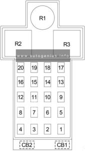
Volkswagen Transporter (T6.1; 2019 – 2021) – fuse box diagram

Volkswagen Transporter (T6.1; 2019 – 2021) – fuse box diagram

Year of production: 2019, 2020, 2021


The Volkswagen Caravelle and Multivan are very similar both in terms of technology and exterior design. The key difference lies in the interior trim and panels. Both models are built on the same platform as the VW Transporter and serve as its passenger version. This article covers the seventh-generation Volkswagen Multivan (T7), produced from 2022 to 2024, as well as the facelifted sixth-generation Volkswagen Transporter/Multivan (T6.1), produced from 2019 to 2021. It provides details on the location of the fuse panels and explains the function of each fuse (fuse layout) and relay.

Volkswagen Transporter T6.1

Source: https://www.flickr.com/photos/peterolthof/


Fuse Holder A

Volkswagen Transporter (T6.1; 2021 - 2021) - fuse box diagram - fuse- holder A
Volkswagen Transporter (T6.1; 2019 – 2021) – fuse box diagram – fuse-
holder A

Assignment of the fuses in the Fuse Holder A

Amps Function/component
SA1 225A Alternator with voltage regulator -CX1- (For models with an alternator with voltage regulator -CX1- (140A/180A) and without a second battery)
SA2 125A X-contact relay -J18-
– Fuses on fuse holder C: 55, 56, 57, 61
Terminal 15 voltage supply relay -J329-
– Fuses on fuse holder C: 9, 10, 39, 40, 42, 43, 44, 46
Fuses on fuse holder C: 1, 28, 29, 30, 31, 32, 33, 34, 35, 36, 37, 53, 60, 61
SA3 100A Fuses in fuse holder H: 1, 2, 3, 5, 6, 7, 8, 9, 10, 11, 12, 17, 18, 19, 20, 25, 26, 27, 28
SA4 80A Main relay-J271- :
– Fuses on fuse holder B: 1, 7, 10, 12, 14, 16, 19, 21, 23, 25, 27, 28, 29, 31, 32, 33
Fuses on fuse holder B: 2, 4, 5, 6, 9, 11, 13, 18, 30, 34
SA5 60A ABS control unit -J104- :
SA6 125A Power steering control unit -J500- :
SA7 100A Radiator fan -VX57- (For models with an alternator with voltage regulator -CX1- (140A/180A) and without a second battery)
Fuse 1 on fuse holder M -SM1- (For models with an alternator with voltage regulator -CX1- (140A/180A) and without a second battery)
SA8 100A Automatic glow period control unit -J179- (For models with an alternator with voltage regulator -CX1- (140A/180A) and without a second battery)
Heated windscreen relay -J47- (For models with an alternator with voltage regulator -CX1- (140A/180A) and without a second battery)
– Fuses on fuse holder B: 8, 26
SA9 125A Rear left turn signal additional relay -J420-
– Left roof mounted turn signal bulb -M23-
Rear right turn signal additional relay -J421-
– Right roof mounted turn signal bulb -M24-
Fuses on fuse holder C: 2, 3, 4, 5, 6, 7, 8, 11, 12, 13, 14, 15, 16, 17, 18, 19, 20, 21, 22, 23, 24, 25, 26, 27, 38, 47, 48, 50, 51, 52, 54, 58
SA10 Connection for battery -A-

Fuse Holder B

Fuse Box Location

Volkswagen Transporter (T6.1; 2021 - 2021) - fuse box location - fuse- holder B
Volkswagen Transporter (T6.1; 2019 – 2021) – fuse box location – fuse- holder B


Fuse box diagram

Volkswagen Transporter (T6.1; 2021 - 2021) - fuse box diagram - fuse holder B
Volkswagen Transporter (T6.1; 2021 – 2021) – fuse box diagram – fuse holder B

Assignment of the fuses in the Fuse Holder B

Amps Function/component
SB1 5A Radiator fan -VX57-
SB2 30A ABS control unit -J104-
SB3
SB4 10A Brake light additional relay -J419-
– High-level brake light bulb -M25-
SB5 10A Selector lever sensors control unit -J587-
Mechatronic unit for dual clutch gearbox -J743-
Ignition key withdrawal lock solenoid -N376-
SB6 10A ABS control unit -J104-
SB7 5A Heater element for crankcase breather -N79-
SB8 30A Heated windscreen -Z2-
SB9 5A Engine control unit -J623-
15A Engine control unit -J623-
SB10 10A Charge pressure control solenoid valve -N75-
Charge pressure control solenoid valve 2 -N274-
Intake manifold flap valve -N316-
Turbine changeover valve -N529-
10A Charge pressure control solenoid valve 2 -N274-
Solenoid for coolant circuit -N492-
Turbine changeover valve -N529-
SB11 10A Magnetic clutch relay -J44-
– Air conditioner compressor -VX81 –
SB12 10A Fuel pressure regulating valve -N276-
10A Fuel metering valve -N290-
SB13 10A Relay for reducing agent metering system -J963-
– Delivery unit for reducing agent metering system -GX19-
– Reducing agent tank -VX85-
SB14 5A Fuel pump relay -J17-
– Fuel delivery unit -GX1-
30A Fuel pump control unit -J538-
– Fuel delivery unit -GX1-
SB15 5A Reversing light switch -F4-
SB16 5A Brake light switch -F-
SB17 5A Centre switch module 3 in dash panel -EX48-
SB18 5A Heated windscreen relay -J47-
SB19 5A Air mass measurement module -GX35-
Clutch position sender-G476-
5A Clutch position sender -G476-
SB20 5A Engine/motor control unit -J623-
SB21 5A Reducing agent tank -VX85-
Control unit for reducing agent heater -J891 –
SB22 10A Auxiliary coolant heater relay -J493- (up to June 2021)
– Heater coolant shut-off valve -N279- (up to June 2021)
Auxiliary coolant heater coolant circuit valve relay -J575- (up to June 2021)
– Heater coolant shut-off valve -N279- (up to June 2021)
SB23 10A Relay for reducing agent metering system -J963-
SB24 5A Selector lever sensors control unit -J587-
Mechatronic unit for dual clutch gearbox -J743-
SB25 5A Oil level and oil temperature sender -G266-
SB26 30A Heated windscreen -Z2-
SB27 10A Charge air cooling pump -V188-
Pump for exhaust gas recirculation cooler -V400-
SB28 15A Control unit for NOx sender -GX30-
Control unit 2 for NOx sender -GX46-
Control unit 3 for NOx sender -GX50-
Control unit 1 for particulate sensor-GX52-
SB29 5A Valve for oil pressure control -N428-
Auxiliary pump for heating -V488-
15A Valve for oil pressure control -N428-
Charge air cooling pump -V188-
Pump for exhaust gas recirculation cooler -V400-
Auxiliary pump for heating -V488-
SB30 20A Fuel pump relay -J17-
– Fuel delivery unit -GX1-
SB31 15A Lambda probe 1 before catalytic converter -GX10-
SB32 30A Engine/motor control unit -J623-
SB33 5A Automatic glow period control unit -J179-
SB34 5A Data bus diagnostic interface -J533-
SB35
SB36


Fuse Holder C

Fuse Box Location

Left-hand drive vehicle.

Volkswagen Transporter (T6.1; 2019 - 2021) - fuse box location - fuse holder C (left-hand drive vehicle)
Volkswagen Transporter (T6.1; 2019 – 2021) – fuse box location – fuse holder C (left-hand drive vehicle)


Right-hand drive vehicle

Volkswagen Transporter (T6.1; 2019 - 2021) - fuse box location - fuse holder C (right-hand drive vehicle)
Volkswagen Transporter (T6.1; 2019 – 2021) – fuse box location – fuse holder C (right-hand drive vehicle)

Fuse Box Diagram

Volkswagen Transporter (T6.1; 2019 - 2021) - fuse box location - fuse holder C
Volkswagen Transporter (T6.1; 2019 – 2021) – fuse box location – fuse holder C

Assignment of the fuses in the Fuse Holder C

Amps Function/component
1 40A Fresh air blower control unit -J126-
– Fresh air blower -V2-
2 30A Switch module for front passenger seat -E664- (right-hand drive models)
Driver seat adjustment control unit -J810- (left-hand drive models)
3 30A Switch module for front passenger seat -E664- (left-hand drive models)
Driver seat adjustment control unit -J810- (right-hand drive models)
4 20A Front passenger seat lumbar support adjustment switch -E177-
Front left lumbar support adjustment switch -E752-
Front right lumbar support adjustment switch -E753-
5 25A Special vehicle control unit -J608-
6 25A Special vehicle control unit -J608-
7 25A Special vehicle control unit -J608-
8 25A Special vehicle control unit -J608-
9 30A Starter relay 1 -J906-
Starter relay 2 -J907-
– Starter -B-
10 30A Fuse 15 on fuse holder B -SB15-
Fuse 17 on fuse holder B -SB17-
Fuse 20 on fuse holder B -SB20-
Fuse 24 on fuse holder B -SB24-
11 20A Auxiliary heater control unit -J364-
12 7.5A Operating and display unit for rear air conditioning system -E265-
Additional display and operating unit 1 -E857-
Heater and air conditioning controls -EX21-
Remote control receiver for auxiliary heater -R64-
13 5A Steering column combination switch -E595-
14 7.5A Circulation pump relay -J160-
– Circulation pump -V55-
15 10A USB connection 1 -U41-
USB charging socket for seat row 3, left -U100-
16 30A Onboard supply control unit -J519-
– Windscreen wiper motor -V-
17 25A Front left headlight -MX1-
18 5A Rear left power latching motor -V307-
Rear right power latching motor -V308-
30A Fuse 1 on fuse holder K -SK1-
Fuse 2 on fuse holder K -SK2-
Fuse 3 on fuse holder K -SK3-
Fuse 4 on fuse holder K -SK4-
19 15A Terminal 15 voltage supply relay 2 -J681-
– Electrical terminal strip for external use -TV65-
20 30A Onboard supply control unit -J519-
Heated rear window relay -J9-
– Heated rear window -Z1 –
– Heated rear window in left wing door -Z26-
– Heated rear window in right wing door -Z27-
21 40A Onboard supply control unit -J519-
– Exterior lighting
22 10A Tachograph -G24-
23 10A Steering column combination switch -E595-
24 5A Anti-theft alarm sensor -G578-
Interior monitoring sensor 2 -G592-
Alarm horn -H12-
25 5A Rain sensor -G213-
26 30A Driver door control unit -J386- (left-hand drive models)
Front passenger door control unit -J387- (right-hand drive models)
27 30A Driver door control unit -J386- (right-hand drive models)
Front passenger door control unit -J387- (left-hand drive models)
28 5A Data bus diagnostic interface -J533-
29 10A Diagnostic connection -U31-
30 5A Rotary light switch -EX1-
31 5A Steering column combination switch -E595-
32 20A Control unit 1 for information electronics -J794-
33 25A Front right headlight -MX2-
34 30A Control unit for reducing agent heater -J891-
35 25A Electrical terminal strip for external use -TV65-
36 30A Onboard supply control unit -J519-
– Horn or dual tone horn -H1-
– Bass horn -H7-
37 40A Onboard supply control unit -J519-
– Exterior lighting
38 25A Onboard supply control unit -J519-
– Exterior lighting
– Interior lighting
– Internal supply
39 10A Airbag control unit -J234-
Warning lamp for airbag deactivated on front passenger side -K145-
40 10A Mirror adjustment switch -E43-
Headlight range control regulator -E102-
Rear fresh air blower switch -E179-
Centre switch module in dash panel -EX22-
Oil level and oil temperature sender -G266-
Pressure sender for refrigerant circuit -G805-
Parking aid control unit -J446-
Coolant shut-off valve relay -J541-
– Climatronic coolant shut-off valve -N422-
Voltage supply relay 2 -J710-
Front left headlight -MX1-
Front right headlight -MX2-
Diagnostic connection -U31-
Left washer jet heater element -Z20-
Right washer jet heater element -Z21-
41 10A not assigned
42 7.5A Rotary light switch -EX1-
Accident data recorder button -E497-
Steering column combination switch -E595-
Interior mirror -EX5-
Tachograph -G24-
Adaptive cruise control unit -J428-
Terminal 15 voltage supply relay 2 -J681-
Accident data memory -J754-
Control unit for external vehicle communication -J1262-
Front camera for driver assist systems -R242-
Automatic anti-dazzle interior mirror -Y7-
43 10A Differential lock control unit -J187-
Vacuum switch for rear differential lock -F363-
44 10A Accident data recorder button -E497-
Accident data memory -J754-
Control unit for ignition bypass -J905-
10-pin connector -T10ce-
12-pin connector -T12f-
10A Taximeter -G41-
Mirror taximeter -G511-
Two-way radio -R8-
45 10A Interface control unit for telematics -J1221-
46 5A Lane change assist control unit -J769-
Lane change assist control unit 2 -J770-
47 10A Ignition/starter switch -D-
– Onboard supply control unit -J519-
– Special vehicle control unit -J608-
– Engine/motor control unit -J623-
48 10A Accident data memory -J754-
49 10A Interface control unit for telematics -J1221-
50 5A Emergency call module control unit and communication unit -J949-
51 5A Dash panel insert -KX2-
– Control unit in dash panel insert -J285-
52 10A Tyre Pressure Monitoring System control unit -J502-
53 10A Display unit for front information display and operating unit control unit -J685-
Reversing camera system control unit -J772-
Two-way signal amplifier for mobile telephone/data services -J984-
Reversing camera -R189-
Storage compartment with interface for mobile telephone -R265-
54 10A Onboard supply control unit -J519-
– heated exterior mirror
55 25A Heated front seats control unit -J774-
56 5A Terminal 75 voltage supply relay 1 -J680-
57 15A Rear window wiper motor -V12-
25A Rear left wing door window wiper motor -V92-
Rear right wing door window wiper motor -V93-
58 15A Electronically controlled damping control unit -J250-
59
60 40A Onboard supply control unit -J519-
– Central locking
61 40A Rear fresh air blower switch -E179-
– Rear fresh air blower -V80-
40A Rear fresh air blower control unit -J391-
– Rear fresh air blower -V80-
Relays
R1 Terminal 15 voltage supply relay 2 -J681-
R2 Circulation pump relay -J160-
R3 Terminal 15 voltage supply relay -J329-
R4 X-contact relay -J18-
R5 Rear left turn signal additional relay -J420-
R6 Rear right turn signal additional relay -J421-

Fuse Holder G

Volkswagen Transporter (T6.1; 2019 - 2021) - fuse box location - fuse holder G
Volkswagen Transporter (T6.1; 2019 – 2021) – fuse box location – fuse holder G

Assignment of the fuses in the Fuse Holder G

Amps Function/component
1 200A Fuses on fuse holder G: 2, 3, 4
Battery monitor control unit 2 -J934-
Second battery -A1-
2 60A Fuses in fuse holder H: 4, 5, 6, 7, 8, 9, 10, 11, 12
3 60A for models with equipment for California:
Fuses in fuse holder H: 13, 14, 15, 16, 25, 26
100A for models with police equipment:
Fuses in fuse holder H: 21, 22, 23, 24, 25, 26
Fuses on fuse holder F: 1, 2 -SF1- (from November 2020)
4 100A for models with equipment for California:
Battery monitor control unit 3 -J1116-
Battery fuse in special vehicle -S339-
– Battery for special vehicle -A24-
300A Body manufacturer


Fuse Holder H

Volkswagen Transporter (T6.1; 2019 - 2021) - fuse box location - fuse holder H
Volkswagen Transporter (T6.1; 2019 – 2021) – fuse box location – fuse holder H


Assignment of the fuses in the Fuse Holder H

Amps Function/component
1 30A Trailer detector control unit -J345-
2 30A Trailer detector control unit -J345-
3 30A Trailer detector control unit -J345-
4 20A/25A Auxiliary air heater control unit -J604-
5 30A Trailer detector control unit -J345-
6 20A Cigarette lighter -U1-
12 V socket -U5-
7 20A 12 V socket 3 -U19-
12 V socket 4 -U20-
12 V socket 5 -U26-
12 V socket 6 -U33-
12 V socket 7 -U117-
12 V socket 8 -U118-
10A Switch-over relay 1 for roof ventilator -J180-
– Roof ventilator -V3-
8 10A Switch-over relay 1 for roof ventilator -J180-
– Roof ventilator -V3-
10A Switch-over relay 1 for roof ventilator -J180-
– Roof ventilator -V3-
15A USB charging socket 1 -U37-
15A Rotating light relay -J326-
Rotating light control unit -J1114-
– Coupling point on left B-pillar, bottom -TBL-
– Coupling point for roof, left -THL-
20A 12 V socket 2 -U18-
20A Rear interior light 4 -WX6-
12 V socket 2 for special vehicles -U84-
9 10A Front stop command light -G954-
Flashing lights relay -J630-
10-pin connector -T10ce-
Coupling point for roof, right -THR-
Coupling point for roof, left -THL-
15A 12 V socket 5 -U26-
12 V socket 6 -U33-
USB charging socket 1 for special vehicles -U91-
20A USB charging socket 2 -U38-
12 V socket 7-U117-
12 V socket 8-U118-
10 10A End position button for cupboard light -E905-
Electric torch -R280-
Surround lighting 1 in rear lid -W61-
Surround lighting 2 in rear lid -W62-
20A 12 V socket for special vehicles -U83-
12 V socket 3 for special vehicles -U85-
11 15A Coupling point for roof, left -THL-
Reading light for pull-out table -W24-
Rear lid light 2 -W101-
Rear interior light 4 -WX6-
30A Onboard charging unit -A11 –
12 5A Operating and display unit for camping equipment -E153-
5A Taximeter -G41-
Mirror taximeter -G511-
15A Two-way radio voltage relay -J84-
25A Two-way radio voltage relay -J84-
13 30A Relay to close convertible roof -J238-
Relay to open convertible roof -J239-
– Hydraulic pump motor -V401-
14 30A Onboard charging unit -A11-
15 5A Left front reading light button -E633-
Rear illumination bulb -L153-
Left rear interior light -W47-
Rear right interior light -W48-
16 7.5A Kitchen background lighting -W122-
17 20A All-wheel drive control unit -J492-
18 5A Differential lock control unit -J187-
19 10A Power latching control unit -J657-
30A Rear lid control unit -J605-
20 5A Voltage supply relay 1 -J701-
Voltage supply relay 2 -J710-
– Parking aid control unit -J446-
21 20A Operating unit for special signals -E507-
22 15A Operating unit for special signals -E507-
23 10A Rotating light relay -J326-
– 12-pin connector -T12f-
24 15A Control unit for ignition bypass -J905-
Terminal 75 voltage supply relay 1 -J680-
– 10-pin connector -T10cg-
– Charging station for hand-held 2-way radio -U24-
25 40A DC/AC converter with socket, 12 V – 230 V -U13-
26 40A Fuse 5 on fuse holder C -SC5-
Fuse 7 on fuse holder C -SC7-
– Special vehicle control unit -J608-
27 40A Rear driver side door control unit -J926- (For left-hand drive models)
Passenger side rear door control unit -J927- (For right-hand drive models)
28 40A Rear driver side door control unit -J926- (For right-hand drive models)
Passenger side rear door control unit -J927- (For left-hand drive models)
Relays
1 Battery isolation relay -J7-
2 Switch-over relay 1 for roof ventilator -J180- (For models with roof ventilator)
Rotating light relay -J326- (For models with special police equipment)
Voltage supply relay 1 -J701- (For right-hand drive models)
Rotating light control unit -J1114- (For models with rotating lights (yellow))
3 Switch-over relay 1 for roof ventilator-J180- (For models with roof ventilator)
Flashing lights relay -J630- (For models with special police equipment)
Voltage supply relay 2 -J710- (For right-hand drive models)
Rotating light control unit -J1114- (For models with rotating lights (yellow))
4 not assigned
5 Heated rear window relay -J9-
6 Differential lock control unit -J187-
7 Voltage supply relay 1 -J701- (For left-hand drive models)
Flashing lights relay 2 -J890- (For models with special police equipment)
8 Two-way radio voltage relay -J84- (For models with special police equipment)
Voltage supply relay 2 -J710- (For left-hand drive models)
9 Relay to close convertible roof -J238- (For models with camping equipment)
10 Relay to open convertible roof -J239- (For models with camping equipment)
11 Terminal 75 voltage supply relay 1 -J680- (For models with special police equipment)
12 Switch-over relay 2 for roof ventilator -J181- (For models with roof ventilator)
Rotating light relay -J326- (For models with rotating lights (yellow))

Fuse Holder J

Volkswagen Transporter (T6.1; 2019 - 2021) - fuse box location - fuse holder J
Volkswagen Transporter (T6.1; 2019 – 2021) – fuse box location – fuse holder J

Assignment of the fuses in the Fuse Holder J

Amps Function/component
SJ1 400A Battery -A-
SJ2 200A Battery isolation relay -J7-
– Fuse 1 on fuse holder G -SG1-
SJ3 100A Radiator fan -VX57-
Fuse 1 on fuse holder M -SM1-
SJ4 100A Automatic glow period control unit -J179-
Heated windscreen relay -J47-
– Fuse 8 on fuse holder B -SB8-
– Fuse 26 on fuse holder B -SB26-
SJ5 200A not assigned
SJ6 200A not assigned
521 Connection for alternator with voltage regulator -CX1-

Fuse Holder K

Volkswagen Transporter (T6.1; 2019 - 2021) - fuse box location - fuse holder K
Volkswagen Transporter (T6.1; 2019 – 2021) – fuse box location – fuse holder K

Assignment of the fuses in the Fuse Holder K

Amps Function/component
SK1 15A Rear right power latching motor -V308-
SK2 5A Rear driver side active door protection control unit -J1093- (For right-hand drive models)
Rear passenger side active door protection control unit -J1094- (For left-hand drive models)
SK3 15A Rear left power latching motor -V307-
SK4 5A Rear driver side active door protection control unit -J1093- (For left-hand drive models)
Rear passenger side active door protection control unit -J1094- (For right-hand drive models)


Fuse Holder M

(For models with hybrid drive).

Volkswagen Transporter (T6.1; 2019 - 2021) - fuse box location - fuse holder M
Volkswagen Transporter (T6.1; 2019 – 2021) – fuse box location – fuse holder M

Assignment of the fuses in the Fuse Holder M

Amps Function/component
1 Automatic glow period control unit -J179-
2 Starter relay 2 -J907-
3 not assigned
4 Heated windscreen relay -J47-
5 Main relay -J271-
6 Coolant shut-off valve relay -J541-
7 Brake light additional relay -J419-
8 Fuel pump relay -J17-
Auxiliary coolant heater relay -J493-
Auxiliary coolant heater coolant circuit valve relay -J575-
9 Starter relay 1 -J906-
10 Magnetic clutch relay -J44-
11 Relay for reducing agent metering system -J963-
12 Fuel pump relay -J17-
13 / -SM1- 40A Control unit for reducing agent heater -J891-

WARNING: Terminal and harness assignments for individual connectors will vary depending on vehicle equipment level, model, and market.

Volkswagen Multivan (T7; 2022 – 2024) – fuse box diagram

Volkswagen Multivan (T7; 2022 – 2024) – fuse box diagram

Year of production: 2022, 2023, 2024


Volkswagen Caravelle and Multivan are very similar both technically and externally. The main difference between them is the interior trim and panels. Both of these models are released on the same base with the wv transporter and represent its passenger version. n this article, we consider the seventh-generation Volkswagen Multivan (T7), produced from 2022 to 2024. Here you will find fuse box diagrams of Volkswagen Multivan T7 2022, 2023, and 2024, get information about the location of the fuse panels inside the car, and learn about the assignment of each fuse (fuse layout) and relay.


Fuse Holder A

Volkswagen Multivan (T7; 2022 - 2024) - fuse box diagram - fuse holder A
Volkswagen Multivan (T7; 2022 – 2024) – fuse box diagram – fuse holder A

Assignment of the fuses in the Fuse Holder A

Amps Function / component
SA1 80A Fuse holder K -SK-
SA2 125A Fuse holder C -SC-
SA3 125A Fuse holder C -SC-
SA4 150A/200A Fuse holder B -SB-
Connection and distribution box 1 -SX1-

Fuse Holder B

Fuse Box Location

Volkswagen Multivan (T7; 2022 - 2024) - fuse box location - fuse holder B
Volkswagen Multivan (T7; 2022 – 2024) – fuse box location – fuse holder B


Fuse box diagram

Volkswagen Multivan (T7; 2022 - 2024) - fuse box diagram - fuse holder B
Volkswagen Multivan (T7; 2022 – 2024) – fuse box diagram – fuse holder B


Assignment of the fuses in the Fuse Holder B

Amps Function / component
SB1 80A Power steering control unit -J500-
SB2 7.5A ABS control unit -J104-
Main relay -J271-
Engine/motor control unit -J623-
Air conditioning system relay -J32- (For models with 1.4L hybrid drive)
– Pressure sender for refrigerant circuit -G805-
– Air conditioner compressor -VX81-
– High-voltage heater (PTC) -ZX17-
Engine sound generator control unit -J943- (For models with 1.4L hybrid drive)
Circulation pump relay -J160-
– Circulation pump 2 -V403-
SB3 10A Power and control electronics for electric drive -JX1- (For models with 1.4L hybrid drive)
Charging unit 1 for high-voltage battery -AX4- (For models with 1.4L hybrid drive)
20A For models with 2.0L petrol engine:
Engine component power supply relay -J757-
– Ignition coil 1 with output stage -N70-
– Ignition coil 2 with output stage -N127-
– Ignition coil 3 with output stage -N291-
– Ignition coil 4 with output stage -N292-
SB4 15A Front left headlight -MX1-
SB5 15A Front right headlight -MX2-
SB6
SB7 30A For models without hybrid drive system:
Auxiliary hydraulic pump 1 for gearbox oil -V475-
SB8
SB9 15A Horn relay -J413-
– Right horn -H34-
SB10 30A Wiper motor relay 1 -J368-
Wiper motor relay 2 -J369-
– Wiper motor control unit -J400-
SB11 7.5A For models without hybrid drive system:
Circulation pump relay -J160-
– Circulation pump 2 -V403-
SB12 15A For models without hybrid drive system:
Mechatronic unit for dual clutch gearbox -J743-
SB13 25A ABS control unit -J104-
SB14 20A Auxiliary heater control unit -J364-
SB15 40A ABS control unit -J104-
SB16 50A Mechatronic unit for dual clutch gearbox -J743- (For models with 1.4L hybrid drive)
SB17 50A Secondary air pump motor -V101- (For models with 2.0L petrol engine)
SB18
SB19 40A Heated windscreen relay for left side -J410-
– Heated windscreen -Z2-
SB20 40A Heated windscreen relay for right side -J411-
– Heated windscreen -Z2-
SB21 7.5A For models without hybrid drive system:
Engine control unit -J623-
SB22 30A For models without hybrid drive system:
Starter -B-
SB23 15A Engine/motor control unit -J623-
SB24 10A For models with 1.4L hybrid drive:
Oil level and oil temperature sender -G266-
Secondary air pump relay -J299-
Activated charcoal filter solenoid valve 1 -N80-
Cut-off valve for activated charcoal filter air flushing -N754-
Inlet camshaft control valve 1 -N727-
Exhaust camshaft control valve 1 -N318-
Valve for oil pressure control -N428-
Radiator fan -VX57-
10A For models with 1.5L petrol engine:
Oil level and oil temperature sender -G266-
Activated charcoal filter solenoid valve 1 -N80-
Inlet camshaft control valve 1 -N727-
Exhaust camshaft control valve 1 -N318-
Valve for oil pressure control -N428-
Inlet cam actuator for cylinder 2 -N583-
Exhaust cam actuator for cylinder 2 -N587-
Inlet cam actuator for cylinder 3 -N591-
Exhaust cam actuator for cylinder 3 -N595-
Radiator fan -VX57-
10A For models with 2.0L petrol engine:
Oil level and oil temperature sender -G266-
Secondary air pump relay -J299-
Engine component power supply relay -J757-
Activated charcoal filter solenoid valve 1 -N80-
Camshaft control valve 1 -N205-
Turbocharger air recirculation valve -N249-
Intake manifold flap valve -N316-
Exhaust camshaft control valve 1 -N318-
Valve for oil pressure control -N428-
Piston cooling jet control valve -N522-
Radiator fan -VX57-
10A For models with 2.0L diesel engine:
Oil level and oil temperature sender -G266-
Automatic glow period control unit -J179-
Control unit for reducing agent heater -J891-
Fuel pressure regulating valve -N276-
Radiator fan -VX57-
Reducing agent tank -VX85-
SB25 10A For models with 1.4L hybrid drive:
Coolant changeover valve 2 -N633-
Coolant pump for high-temperature circuit -V467-
Coolant valve for gearbox -N488-
SB26 10A For models with 1.4L hybrid drive:
Activated charcoal filter air flushing pump -V700-
Charge air cooling pump -V188-
10A For models with 2.0L petrol engine:
Coolant valve for gearbox -N488-
Coolant circulation pump -V50-
10A For models with 2.0L diesel engine:
Heater element for crankcase breather -N79-
Valve for oil pressure control -N428-
Coolant regulating valve -N515-
Piston cooling jet control valve -N522-
Coolant pump for high-temperature circuit -V467-
Auxiliary pump for heating -V488-
SB27 10A For models with 1.4L hybrid drive, for models with 2.0L petrol engine:
Lambda probe 1 after catalytic converter -GX7-
Lambda probe 1 before catalytic converter -GX10-
10A For models with 1.5L petrol engine:
Lambda probe 1 after catalytic converter -GX7-
Lambda probe 1 before catalytic converter -GX10-
Charge air cooling pump -V188-
15A For models with 2.0L diesel engine:
Control unit for NOx sender -GX30-
Control unit 2 for NOx sender -GX46-
Control unit 3 for NOx sender -GX50-
Control unit 1 for particulate sensor -GX52-
SB28 10A For models with 2.0L petrol engine:
Cam adjustment actuator 1 -F366-
Cam adjustment actuator 2 -F367-
Cam adjustment actuator 3 -F368-
Cam adjustment actuator 4 -F369-
Cam adjustment actuator 5 -F370-
Cam adjustment actuator 6 -F371-
Cam adjustment actuator 7 -F372-
Cam adjustment actuator 8 -F373-
20A For models with 1.4L hybrid drive, for models with 1.5L petrol engine:
Ignition coil 1 with output stage -N70-
Ignition coil 2 with output stage -N127-
Ignition coil 3 with output stage -N291-
Ignition coil 4 with output stage -N292-
SB29 15A For models with 1.4L hybrid drive, for models with 1.5L petrol engine, for models with 2.0L petrol engine:
Fuel pump control unit -J538-
– Fuel delivery unit -GX1-
20A For models with 2.0L diesel engine:
Fuel pump control unit -J538-
– Fuel delivery unit -GX1-
SB30 10A Fuel tank shut-off valve -N288- (For models with 1.4L hybrid drive)
Auxiliary pump for heating -V488- (For models with 1.4L hybrid drive)
Coolant circulation pump before power and control electronics for electric drive -V508- (For models with 1.4L hybrid drive)
SB31
SB32 40A Brake servo -NX6-
Relays
R1 Main relay -J271- (For models with petrol engine)
R2 Secondary air pump relay -J299- (For models with 2.0L petrol engine)
R3 Horn relay -J413-
R4 Starter relay 1 -J906- (For models with no hybrid drive)
R5 Starter relay 2 -J907- (For models with no hybrid drive)
R6 Air conditioning system relay -J32- (For models with hybrid drive)
Engine component current supply relay -J757- (For models with 2.0L petrol engine)
R7 Automatic glow period control unit -J179- (For models with diesel engine)
R8
R9 Heated windscreen relay for left side -J410-
R10 Heated windscreen relay for right side -J411-
R11 Wiper motor relay 1 -J368-
R12 Wiper motor relay 2 -J369-


Fuse Holder C

Fuse Box Location

Left-hand drive vehicle.

Volkswagen Multivan (T7; 2022 - 2024) - fuse box location - fuse holder C (left-hand drive vehicle)
Volkswagen Multivan (T7; 2022 – 2024) – fuse box location – fuse holder C (left-hand drive vehicle)


Right-hand drive vehicle

Volkswagen Multivan (T7; 2022 - 2024) - fuse box location - fuse holder C (right-hand drive vehicle)
Volkswagen Multivan (T7; 2022 – 2024) – fuse box location – fuse holder C (right-hand drive vehicle)


Fuse Box Diagram

Volkswagen Multivan (T7; 2022 - 2024) - fuse box diagram - fuse holder C
Volkswagen Multivan (T7; 2022 – 2024) – fuse box diagram – fuse holder C

Assignment of the fuses in the Fuse Holder C

Amps Function / component
SC1 40A Passenger side rear door control unit -J927- (For left-hand drive models)
Rear driver side door control unit -J926- (For right-hand drive models)
SC2 30A Rear fresh air blower control unit -J391-
SC3 25A Trailer detector control unit -J345-
SC4 30A Rear lid control unit -J605-
SC5 25A Parking lock actuator -V682-
SC6 30A Onboard supply control unit -J519-
SC7 30A Heater and air conditioning system control unit -J979-
SC8 20A For left-hand drive models:
Driver seat lumbar support adjustment switch -E176-
Driver seat adjustment control unit -J810-
20A For right-hand drive models:
Front passenger seat lumbar support adjustment switch -E177-
Front passenger seat adjustment operating unit -E471-
SC9 30A Driver door control unit -J386- (For left-hand drive models)
Front passenger door control unit -J387- (For right-hand drive models)
SC10 30A Control unit for power-operated seat rails, left-side -J1255-
SC11 15A Trailer detector control unit -J345-
SC12 40A Onboard supply control unit -J519-
SC13 40A Onboard supply control unit -J519-
SC14 40A Digital sound package control unit -J525-
SC15
SC16 7.5A Airbag control unit -J234-
Control unit for wireless connection of seat occupied sensors -J1247-
SC17 15A Heater and air conditioning system control unit -J979-
SC18 7.5A Control unit for electronic steering column lock -J764-
Entry and start authorisation control unit -J965-
Control unit 2 for break-in protection -J1192-
Control unit 3 for break-in protection -J1193-
Control unit 4 for break-in protection -J1194-
Control unit 5 for break-in protection -J1195-
SC19 7.5A Dash panel insert -KX2-
Emergency call module control unit and communication unit -J949-
SC20 7.5A Internet access control unit -J666-
Control unit for overhead view camera -J928-
Reversing camera -R189-
Storage compartment with interface for mobile telephone -R265-
Transmission and reception stabilisation control unit -R308-
USB connection 1 -U41-
SC21 7.5A Lane change assist control unit -J769-
Lane change assist control unit 2 -J770-
SC22 5A Front left seat backrest fan 1 -V512-
Front left seat cushion fan 1 -V514-
Front right seat backrest fan 1 -V516-
Front right seat cushion fan 1 -V518-
SC23
SC24 7.5A Rear right power latching motor -V308-
Right sliding door relay -J1270-
– Rear right sliding door lock unit -VX108-
SC25 25A Front left seat belt -NX10- (For left-hand drive models)
– For models with control unit for front left belt tensioner -J854-
Front right seat belt -NX11- (For right-hand drive models)
– For models with control unit for front right belt tensioner -J855-
SC26 30A Front passenger door control unit -J387- (For left-hand drive models)
Driver door control unit -J386- (For right-hand drive models)
SC27 25A Front right seat belt -NX11- (For left-hand drive models)
– For models with control unit for front right belt tensioner -J855-
Front left seat belt -NX10- (For right-hand drive models)
– For models with control unit for front left belt tensioner -J854-
SC28 10A Maintenance connector for high-voltage system -TW- (For models with hybrid drive system)
High-voltage battery 1 -AX2- (For models with hybrid drive system)
SC29 15A Trailer detector control unit -J345-
SC30 30A Control unit 1 for information electronics -J794-
SC31 25A Trailer detector control unit -J345-
SC32 30A Control unit for power-operated seat rails, right-side -J1256-
SC33 7.5A Rear left power latching motor -V307-
Left sliding door relay -J1269-
– Rear left sliding door lock unit -VX107-
SC34 20A For left-hand drive models:
Front passenger seat lumbar support adjustment switch -E177-
Front passenger seat adjustment operating unit -E471-
20A For right-hand drive models:
Driver seat adjustment control unit -J810-
Driver seat lumbar support adjustment switch -E176-
SC35 40A Onboard supply control unit -J519-
SC36 40A Fresh air blower control unit -J126-
SC37 40A Control unit for reducing agent heater -J891- (For models with diesel engine)
SC38
SC39 10A Steering column electronics control unit -J527-
SC40 7.5A Anti-theft alarm system horn -H8-
SC41 7.5A Data bus diagnostic interface -J533-
SC42 7.5A Selector mechanism -EX2-
Selector lever position display -Y6-
SC43 7.5A Operating and display unit for rear air conditioning system -E265-
Vehicle interior temperature sensor -G1090-
Rear lid power opening control unit -J938-
Heated rear window relay -J9-
Control unit for contactless opening of sliding door, driver side -J1321-
Control unit for contactless opening of sliding door, passenger side -J1322-
Remote control receiver for auxiliary heater -R64-
SC44 7.5A Parking brake button -EX12-
Centre switch module in dash panel -EX22-
Operating unit for lighting -EX59-
Interior monitoring sensor -G273-
Anti-theft alarm sensor -G578-
Air humidity, rain and light sensor -G823-
Control unit for cornering light and headlight range control -J745-
Diagnostic connection -U31-
Front interior light -WX1-
SC45 7.5A Steering column electronics control unit -J527-
SC46 7.5A Display unit for front information display and operating unit control unit -J685-
Control unit for Head-up Display -J898-
SC47 10A Electronically controlled damping control unit -J250-
SC48
SC49
SC50
SC51
SC52 20A 12 V socket -U5-
12 V socket 2 -U18-
12 V socket 3 -U19-
SC53
SC54
SC55
SC56
SC57
SC58 7.5A Adaptive cruise control unit -J428-
Parking aid control unit -J446-
Park assist steering control unit -J791-
Front camera for driver assist systems -R242-
SC59 7.5A Parking brake button -EX12-
Air quality sensor -G238-
Pressure sender for refrigerant circuit -G805-
Automatic anti-dazzle interior mirror -Y7-
SC60 7.5A Diagnostic connection -U31-
SC61 7.5A Starter relay 1 -J906- (For models without hybrid drive system)
Starter relay 2 -J907- (For models without hybrid drive system)
7.5A Power and control electronics for electric drive -JX1- (For models with hybrid drive system)
SC62 7.5A USB charging socket for seat row 2, left -U98-
USB charging socket for seat row 2, right -U99-
USB chafging socket for seat row 3, left -U100-
USB charging socket for seat row 3, right -U101-
SC63 10A For models with taxi equipment:
Taximeter -G41-
Mirror taximeter -G511-
Two-way radio -R8-
SC64
SC65
SC66 15A Rear window wiper motor -V12-
SC67 30A Heated rear window -Z1 –
Relays
R1
R2 Terminal 15 voltage supply relay -J329-
R3 Heated rear window relay -J9-
Fitting location of individual fuses
Volkswagen Multivan (T7; 2022 - 2024) - fuse box diagram - fuse holder C (fitting location of individual fuses)
Volkswagen Multivan (T7; 2022 – 2024) – fuse box diagram – fuse holder C (fitting location of individual fuses)

Fuse Holder H

(For models with hybrid drive).

Volkswagen Multivan (T7; 2022 - 2024) - fuse box diagram - fuse holder H
Volkswagen Multivan (T7; 2022 – 2024) – fuse box diagram – fuse holder H


Assignment of the fuses in the Fuse Holder H

Amps Function / component
SH1 200A Connection and distribution box 1 -SX1-
Jump start connection -TV32-
SH2 80A Fuse holder K -SK-


Fuse Holder K

(For models with hybrid drive).

Volkswagen Multivan (T7; 2022 - 2024) - fuse box diagram - fuse holder K
Volkswagen Multivan (T7; 2022 – 2024) – fuse box diagram – fuse holder K


Assignment of the fuses in the Fuse Holder K

Amps Function / component
SK1
SK2
SK3
SK4
SK5 25A Special vehicle control unit -J608-
SK6 25A Special vehicle control unit -J608-
SK7 25A Special vehicle control unit -J608-
SK8 25A Special vehicle control unit -J608-
SK9 7.5A Taximeter -G41-
Mirror taximeter -G511-
SK10
SK11
SK12
Relays
R1
R2
R3
R4 Right sliding door relay -J1270-
R5 Circulation pump relay -J160-
R6
R7

Fuse Holder O

Volkswagen Multivan (T7; 2022 - 2024) - fuse box diagram - fuse holder O
Volkswagen Multivan (T7; 2022 – 2024) – fuse box diagram – fuse holder O

Assignment of the fuses in the Fuse Holder O

Amps Function / component
A 400A Alternator with voltage regulator -CX1-
Starter -B-

Fuse Holder P

Volkswagen Multivan (T7; 2022 - 2024) - fuse box diagram - fuse holder P
Volkswagen Multivan (T7; 2022 – 2024) – fuse box diagram – fuse holder P

Assignment of the fuses in the Fuse Holder P

Amps Function / component
SP1 150A Fuse holder B -SB- (For models with hybrid drive system)
SP2 100A Radiator fan -VX57-
SP3 200A Fuse 1 in fuse holder H -SH1- (For models with hybrid drive system)
508 Threaded connection (30) on E-box:
Power and control electronics for electric drive -JX1- (For models with hybrid drive system)
Terminal 30 wiring junction -TV2- (For models with no hybrid drive system)
SP4 125A Fuse holder C -SC- (For models with hybrid drive system)
SP5 125A Fuse holder C -SC- (For models with hybrid drive system, from June 2022)


High-voltage system fuse 1 – S350-

(For models with hybrid drive).

Volkswagen Multivan (T7; 2022 - 2024) - fuse box diagram - high-voltage system fuse 1 - S350-
Volkswagen Multivan (T7; 2022 – 2024) – fuse box diagram – high-voltage system fuse 1 – S350-


Amps Function / component
A 350A High-voltage battery 1 -AX2-

High-voltage system fuse 3 – S353-

(For models with hybrid drive).

Volkswagen Multivan (T7; 2022 - 2024) - fuse box diagram - high-voltage system fuse 3 - S353-
Volkswagen Multivan (T7; 2022 – 2024) – fuse box diagram – high-voltage system fuse 3 – S353-


Amps Function / component
A 80A Power and control electronics for electric drive -JX1-


Relay in switching unit for high-voltage battery – SX6-

Volkswagen Multivan (T7; 2022 - 2024) - fuse box diagram - relay in switching unit for high-voltage battery -SX6-
Volkswagen Multivan (T7; 2022 – 2024) – fuse box diagram – relay in switching unit for high-voltage battery -SX6-


Function / component
R1 Precharge contactor for high-voltage battery -J1044-
R2 High-voltage battery power contactor 1 -J1057-
R3 High-voltage battery power contactor 2 -J1058-

WARNING: Terminal and harness assignments for individual connectors will vary depending on vehicle equipment level, model, and market.
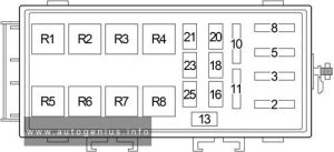
Volkswagen Lupo (2000 – 2006) – fuse box diagram

Volkswagen Lupo (2000 – 2006) – fuse box diagram

Year of  production: 2000, 2001, 2002, 2003, 2004,2005, 2006


Volkswagen Lupo was produced mainly in the body of a 3-door hatchback in 1998, 1999, 2000, 2001, 2002, 2003, 2004, 2005 and 2006. Positioned as a city car with low fuel consumption. In this material you will find a designation of the purpose of fuses and relays in Volkswagen Lupo, diagrams of the boxes in which they are located.

Passenger compartment

Fuse box location

The fuse panel is located behind the cover on the driver’s side of dash panel.

Volkswagen Lupo (2000 - 2006) - fuse box location - passenger compartment
Volkswagen Lupo (2000 – 2006) – fuse box location – passenger compartment

  1. Switch off the ignition and the component concerned.
  2. Remove cover towards the front.
  3. With the aid of the list of fuses determine which fuse belongs to the component that has failed.
  4. Replace blown fuse – can be recognized by the burnt metal strip – with a fuse of same amperage.

Fuse box diagram

Volkswagen Lupo (2000 - 2006) - fuse box diagram - passenger compartment
Volkswagen Lupo (2000 – 2006) – fuse box diagram – passenger compartment
Amps Consumer
SB1 10A Lambda probe heater / Air mass meter
SB2 5A Number plate lights
SB3 5A/10A Injectors
Mapped controlled engine cooling thermostat, fuel metering valve, intake manifold flap air flow control valve, camshaft timing adjustment valve
SB4 5A Left side lights
SB5 5A Left side lights
SB6 15A Rear wiper
SB7 7.5A Turn signal system
SB8 5A ABS/ESP
SB9 5A Headlight range control
SB10 5A Interior lights
Self-diagnosis connection (3L)
SB11 5A Self-diagnosis connection, dash panel insert, Climatronic, ESP control unit, Steering angle sender
SB12 10A Right main beam, main beam warning lamp
SB13 10A Left main beam
SB14 10A Hazard warning system, anti-theft alarm system, remote control system
SB15 10A Brake lights
SB16 5A Radio
Central locking and anti-theft alarm control unit
Dash panel insert
Ignition switch S-contact
SB17 5A Folding mirrors
SB18 5A/15A Mirror heating
SB19 15A Dual tone horn, heated washer jets
SB20 5A/10A CD changer, telephone
SB21 5A/10A/15A Automatic gearbox control unit
Electronic manual gearbox control unit
SB22 15A ATA horn
SB23 5A Supplementary heater relay, glow plug relays, throttle butterfly valve, exhaust gas regulation relay, speed sender, charge pressure sender
SB24 5A Clutch pedal switch (diesel), brake light switch, Motronic control unit, radiator fan control unit
SB25 5A Automatic gearbox selector lever, electric vent wing window
SB26 7.5A/5A Central locking control unit, electrically adjustable exterior mirror, air conditioner, navigation, mobile telephone
Mirror heating
SB27 5A Dash panel insert
SB28 5A Speedometer sender, immobilizer
SB29 7.5A Reversing lights, washer jets heater elements, headlight range control
SB30 5A/7.5A Exhaust gas recirculation valve, activated charcoal filter solenoid valve, heater tube, pressure control valve
SB31 10A Engine control unit, electronic manual gearbox control unit
SB32 5A/10A Engine control unit
Crash fuel shut-off control unit
SB33 10A Automatic gearbox control unit, electronic manual gearbox control unit
SB34 10A Ignition transformer
Speedometer sender
SB35 20A/25A Sliding/tilting sunroof
SB36 15A Simos (injection system) control unit, 4LV (injection system) control unit, electronic manual gearbox control unit
SB37 15A Engine control unit
Metering adjuster, electronic shut-off valve
SB38 25A Left electric windows
Left door control unit
SB39 25A Right electric windows
Right door control unit
SB40 15A Fuel pump
SB41 15A Central locking system control unit, anti-theft alarm system, remote control system
SB42 15A Radio, navigation, CD changer
SB43 15A Front fog lights, rear fog light
SB44 15A Left dipped beam
Headlight range control adjuster
SB45 15A Right dipped beam
SB46 15A Cigarette lighter
SB47 15A/20A/30A Headlight washer system pump, gearbox hydraulic pump relay
Horn (GTI)
SB48 20A Heated rear window
SB49 25A Fresh air blower
SB50 15A Front wiper, windscreen washer pump
SB51 15A Heated seats

Engine Compartment

Fuse box location

Fuse box placed on the battery of the engine compartment.

Volkswagen Lupo (2000 - 2006) - fuse box location - engine compartment
Volkswagen Lupo (2000 – 2006) – fuse box location – engine compartment

Fuse box diagram

Version 1
Volkswagen Lupo (2000 - 2006) - fuse box diagram - engine compartment (version 1)
Volkswagen Lupo (2000 – 2006) – fuse box diagram – engine compartment (version 1)
Amps Function/component
SA1 150A Alternator
SA2 80A Fuse carrier B
Fuse SA2 is located in luggage compartment next to battery
SA3 50A Engine glow plugs
SA4 80A Electro-hydraulic power steering motor (ARR, AYZ)
Coolant heater elements (ARR, AYZ)
Radiator fan control unit (only models with air conditioner, ARR, AYZ)
Radiator fan (ARR, AYZ)
SA5 30A Radiator fan (AMF)
SA6 30A ABS with EDL control unit
SA7 30A ABS with EDL control unit
SA8 10A/20A Radiator fan (AVY, ARR)
Radiator fan control unit (only models with air conditioner, AVY, ARR)
SA9 30A/10A Radiator fan control unit (only models with air conditioner, AVY, ARR)


Version 2
Volkswagen Lupo (2000 - 2006) - fuse box diagram - engine compartment (version 2)
Volkswagen Lupo (2000 – 2006) – fuse box diagram – engine compartment (version 2)
Amps Function/component
SA1 150A Alternator
SA2 80A Fuse carrier B
Fuse SA2 is located in luggage compartment next to battery
SA3 50A Engine glow plugs
SA4 80A Electro-hydraulic power steering motor (ARR, AYZ)
Coolant heater elements (ARR, AYZ)
Radiator fan control unit (only models with air conditioner, ARR, AYZ)
Radiator fan (ARR, AYZ)
SA5 30A Radiator fan (AMF)
SA6 30A ABS with EDL control unit
SA7 30A ABS with EDL control unit
SA8 10A/20A Radiator fan (AVY, ARR)
Radiator fan control unit (only models with air conditioner, AVY, ARR)
SA9 30A/10A Radiator fan control unit (only models with air conditioner, AVY, ARR)


WARNING: Terminal and harness assignments for individual connectors will vary depending on vehicle equipment level, model, and market.
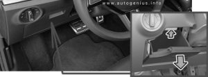
Dodge Durango (2020 – 2024) – fuse and relay box diagram

Dodge Durango (2020 – 2024) – fuse and relay box diagram

Year of production: 2020, 2021, 2022, 2023, 2024


Engine compartment

Fuse box location

The Power Distribution Center is located in the engine compartment near the battery jump start posts.

Dodge Durango (2020 - 2024) - fuse box location - engine compartment
Dodge Durango (2020 – 2024) – fuse and relay box location – engine compartment


This center contains cartridge fuses, micro fuses, relays, and circuit breakers. A description of each fuse and component may be stamped on the inside cover, otherwise the cavity number of each fuse is stamped on the inside cover.

Fuse box diagram

Dodge Durango (2020 - 2024) - fuse box diagram - engine compartment
Dodge Durango (2020 – 2024) – fuse and relay box diagram – engine compartment

Cartridge Fuse Micro Fuse Description
F01 Spare
F02 Spare
F03 60A Yellow Radiator Fan
F04 60A Yellow 2021-2024: ESC Pump (NON-SRT)
F05 40A Green Air Suspension Compressor
F06 40A Green ABS Pump (SRT)
F07 30A Pink Starter Solenoid
F08 Spare
F09 30A Pink Diesel Fuel Heater (Diesel Engine Only) / Brake Vacuum Pump
F10 40A Green Body Controller (CBC) #2 / Exterior Lighting
F11 30A Pink Trailer Tow Electric Brake
F12 40A Green Body Controller (CBC) #3 / Power Locks
F13 40A Green Blower Motor Front
F14 40A Green Body Controller (CBC) #4 / Exterior Light
F15 40A Green Low Temperature Radiator (LTR) Engine Cooling Pump*
F16 Spare
F17 30A Pink Headlamp Washers
F18 Spare
F19 20A Blue Headrest Solenoid
F20 30A Pink Passenger Door Module
F21 Spare
F22 20A Blue 2020: Engine Control Module
2021-2024: Engine Control Module / Power Control Module
F23 30A Pink Body Controller (CBC) #1 / lnterior Light
F24 30A Pink Driver Door Module
F25 30A Pink Front Wipers
F26 30A Pink ESP/ECU Valves
F27 Spare
F28 20A Blue Trailer Tow Backup Lights
F29 20A Blue Trailer Tow Parking Lights
F30 30A Pink 2020-2021: Trailer Tow (Receptacle) / Trailer Tow (Separate E-Brake) / Trailer Tow (BUX)
2022-2024: Trlr Tow Pwr
F31 Spare
F32 30A Pink Drive Train Control Module
F33 Spare
F34 30A Pink Slip Differential Control (ELSD)
F35 30A Pink Sunroof
F36 30A Pink 2020: Rear Defroster/ Electronic BackLight (EBL)
2021-2024: Electronic BackLight (EBL)
F37 25A Clear HVAC Rear Blower Motor
F38 30A Pink Power Inverter 115 Volt AC
F39 30A Pink Power Liftgate
F40 10A Red Daytime Running Lights / Headlamp Leveling
F41 Spare
F42 20A Yellow Horn
F43 Spare
F44 10A Red Diagnostic Port
F45 5A Tan Cyber Security MOD
F46 Spare
F47 Spare
F48 Spare
F49 10A Red Integrated Central Stack / Climate Control
F50 20A Yellow Air Suspension Control Module / Slip Differential (ELSD)
F51 15A Blue KIN / RF HUB / Steering Column Lock (ESCL)
F52 Spare
F53 20A Yellow Trailer Tow – Left Turn / Stop Lights
F54 Spare
F55 Spare
F56 15A Blue PCM
F57 20A Yellow NOX Sensor / PM Sensor / Fuel HTR
F58 15A Blue HID Headlamps LH
F59 10A Red SCR Pumps Relay
F60 15A Blue Transmission Control Module (TCM)
F61 10A Red 2020: Transmission Control Module/PM Sensor (Diesel Engine Only)
2021-2024: PM Sensor
F62 10A Red Air Conditioning Clutch
F63 20A Yellow 2020-2021: Ignition Coils / Ignition Coil Capacitors / Short Runner Valve Actuator – If Equipped (Gas); Urea Heater (Diesel)
2022-2024: Ignition Coils / Ignition Coil Capacitors
F64 25A Clear Fuel Injectors / Powertrain (PCM/ECM)
F65 Spare
F66 10A Red Sunroof / Rain Sensor (LRSM) / Inside Rear View Mirror (RVM) / USB Port / DSCR / DTV / WCP
F67 15A Blue CDM / UCI Port / USB Port
F68 20A Yellow Rear Wiper Motor
F69 15A Blue Spotlight Feed
F70 20A Yellow Fuel Pump Motor
F71 30A Green Amplifier / ANCM
F72 10A Red ECM/PCM
F73 15A Blue HID Headlamp RH
F74 Spare
F75 10A Red Dual Battery Control
F76 10A Red 2020: Anti-lock Brakes / Electronic Stability Control
2021-2024: ESP
F77 10A Red 2020: Drivetrain Control Module / Front Axle Disconnect Module
2021-2024: Drivetrain Control Module / ELSD
F78 10A Red Engine Control Module (ECM) / Electric Power Steering (EPS) / PCM
F79 Spare
F80 10A Red 2020-2022: Universal Garage Door Opener (UGDO) / Anti-Intrusion Module / Siren
2023-2024: Universal Garage Door Opener (UGDO)
F81 20A Yellow Trailer Tow Right Turn/Stop Lights
F82 10A Red Steering Column Control Module (SCCM) / Cruise Control / DTV
F83 10A Red Fuel Door
F84 15A Blue Instrument Cluster
F85 10A Red Airbag Module (ORC)
F86 10A Red Airbag Module (ORC)
F87 10A Red Air Suspension MOD
F88 15A Blue Instrument Panel Cluster / SGW / ITBM
F89 Spare
F90 Spare
F91 20A Yellow 2020: Power Outlet (Rear Seats) Selectable
2021-2024: Power Outlet Cargo Area
F92 10A Red 2020: Rear Console Lamp
2021-2024: Rear Console Lamp / RR Power Outlet
F93 20A Yellow Cigar Lighter
F94 10A Red Shifter / Transfer Case Module
F95 10A Red Rear Camera / Blind Spot Sensor
F96 10A Red 2020: Rear Seat Heater Switch / Flashlamp Charger
2021-2024: Rear Seat Heater Switch
F97 20A Yellow Rear Heated Seats / Heated Steering Wheel
F98 20A Yellow Ventilated Seats / Front Heated Seats
F99 10A Red Climate Control / Driver Assistance Systems Module / HALF / Parktronx
F100 10A Red Active Damping
F101 15A Blue 2020-2022: ECCM / SMRT Hl-Beams
2023-2014: In Car Temp Sensor / Humidity Sensor
F102 15A Blue Spare
F103 10A Red 2020: Cabin Heater (Diesel Engine Only) / Rear HVAC
2021-2024: PTC / Rear HVAC
F104 20A Yellow Power Outlets (Instrument Panel/Center Console/Rear Cargo)

WARNING: Terminal and harness assignments for individual connectors will vary depending on vehicle equipment level, model, and market.
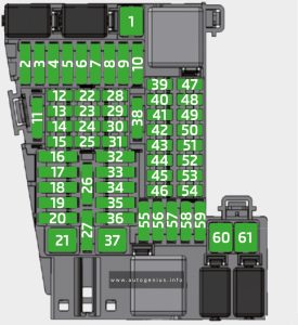
Dodge Durango (2001 – 2003) – fuse and relay box diagram

Dodge Durango (2001 – 2003) – fuse and relay box diagram

Year of  production: 2001, 2002, 2003

Passenger compartment

Fuse box location

The fuse panel is located behind the cover on the driver’s side of dash panel.

Dodge Durango - fuse box location - passenger compartment
Dodge Durango – fuse and relay box location – passenger compartment


Fuse box diagram

Dodge Durango (2001 - 2003) - fuse box diagram - passenger compartment
Dodge Durango (2001 – 2003) – fuse and relay box diagram – passenger compartment


Assignment of the fuses in the engine compartment

Amps Description
1 15A Sentry Key Immobilizer, Instrument Cluster, Radio, Center Console Lamp, Overhead Console, Front/Rear Dome Lamp, Glove Box Lamp/Switch, Data Link Connector, Driver Door Module, Right/Left Visor/Vanity Mirror & Liftgate Lamp
2 20A Horn Relay & Clockspring
3
4 20A Central Timer Module, Headlamp Switch, Left/Right Tail Lamp Assembly, Left/Right Front Park/Turn Signal Lamps, Left/Right Front Side Marker Lamp & License Plate Lamp
5 20A Front Wiper Relay, Front Wiper Motor & Central Timer Module
6
7
8 10A Transmission Control Module & Instrument Cluster
9 5A Rear A/C Heater Control, Overhead Console, Transfer Case Selector Switch, Shift Bezel Lamp, Radio, Cigar Lighter, A/C Heater Control & Instrument Cluster
10 10A Powertrain Control Module, Fuel Pump Relay, Radiator Fan Relay & Sentry Key Immobilizer
11 10A A/C Compressor, Proportional Purge Solenoid, Automatic Day/Night Mirror, Overhead Console, Central Timer Module & Transfer Case Selector Switch
12 10A Engine Starter Motor Relay & Transmission Control Module
13 15A Amplifier
14 10A Instrument Cluster
15 10A Driver/Passenger Power Mirror
16
17 15A Cigar Lighter
18 10A Radio
19 10A Combination Flasher
20 10A Airbag Control Module
21 10A Airbag Control Module
22 20A Heated Seat Module & Passenger/Driver Heated Seat Module
23
24 15A Rear Window Defogger Relay & Rear Blower Motor Relay
25 10A A/C Heater Control
26 15A Transmission Solenoid, Transmission Range Sensor & Passenger Door Power Lock Switch
27 10A Controller Anti-Lock Brake
28 25A CB Driver Door Module (Power Window)
29
R1 Horn Relay
R2 Park Lamp Relay

Engine Compartment

Fuse box location

Dodge Durango - fuse box location - engine compartment
Dodge Durango (2001 – 2003) – fuse and relay box location – engine compartment


Fuse box diagram

Dodge Durango (2001 - 2003) - fuse box diagram - engine compartment
Dodge Durango (2001 – 2003) – fuse and relay box diagram – engine compartment


Assignment of the fuses in the engine compartment

Amps Description
A 20A Transfer Case Control Module
B 10A A/C Compressor Clutch Relay
C 20A Trailer Tow Connector
D 20A Junction Block & Front/Center/Rear Power Outlet
E 20A Ignition Switch
F 20A Transmission Control Relay
G
H 20A Fog Lamp Relay
J 20A Rear Wiper Relay
K 25A Rear Blower Motor Relay
L
M
N
P
R
S
T 10A Left/Right Front Park/Turn Signal Lamps, Left/Right Side Marker Lamp & License Lamp
U 20A Oxygen Sensors, Fuel Injectors Coil On Plugs, Powertrain Control Module & Ignition Coil
1 20A/30A Combination Flasher
2 20A Powertrain Control Module, Automatic Shut Down Relay & Fuel Pump Module/Relay
3 20A Central Timer Module
4 40A Rear Window Defogger Relay
5 20A Brake Lamp Switch
6 30A Electric Brake
7 40A Junction Block
8 40A Controller Anti-Lock Brake
9 50A Ignition Switch
10 40A Ignition Switch
11 30A Automatic Shut Down Relay
12 20A Central Timer Module
13 40A Ignition Switch
14 50A Driver/Passenger Power Seat Switch
15 50A Radiator Fan Relay & Driver/Passenger Power Relay
16 50A Engine Starter Motor Relay
17 50A Ignition Switch
R1 Radiator Fan Relay
R2 Automatic Shut Down (ASD) Relay
R3  –
R4 Rear Blower Motor Relay
R5  –
R6 EBL Relay
R7 Fuel Pump Relay
R8  –
R9 Air Conditioner Compressor Clutch Relay
R10 Fog Lamp Relay
R11  –
R12 Oxygen Sensor Relay
R13  –
R14 Transmission Control Relay
R15  –
R16  –
R17 Starter Relay
R18 Front Wiper Relay
R19 Rear Wiper Relay


WARNING: Terminal and harness assignments for individual connectors will vary depending on vehicle equipment level, model, and market.
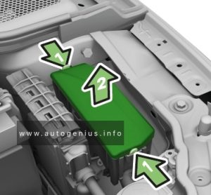
Dodge Durango (1998 – 2000) – fuse and relay box diagram

Dodge Durango (1998 – 2000) – fuse and relay box diagram

Year of  production: 1998, 1999, 2000

Passenger compartment

Fuse box location

The fuse panel is located behind the cover on the driver’s side of dash panel.

Dodge Durango - fuse box location - passenger compartment
Dodge Durango (1998 – 2000) – fuse box location – passenger compartment

Fuse box diagram

Dodge Durango - fuse box diagram - passenger compartment
Dodge Durango (1998 – 2000) – fuse box diagram – passenger compartment


Assignment of the fuses in the instrument panel

Amps Description
1 20A Brake Lamp Switch
or
Headlamp Relay & A/C Compressor Clutch Relay
2 15A/20A Daytime Running Lamp, Passenger Door Lock Switch, Park/Neutral Position Switch
3 10A Controller Anti-Lock Brake
4 15A Power Amplifier
5 5A Headlamp Switch, Overhead A/C Control, Instrument Cluster, Radio, Rear Wiper/Defogger Switch, Ash Receiver Lamp & A/C-Heater Control
6 20A Central Timer Module, Multifunction Switch, Wiper Motor, Wiper Relay & Junction Block
7 15A A/C Low Temperature Cut-Out Switch, Blower Motor Relay, A/C Compressor Clutch Relay & Rear Wiper/Defogger Switch
8 10A Radio
9 10A Automatic Shut Down Relay, Fuel Pump Relay & Powertrain Control Module
10 15A
11 10A Diagnostic Connector, Overhead Console, Automatic Day/Night Mirror, Central Timer Module & Duty Cycle Evap/Purge Solenoid
12 15A Left/Right Courtesy Lamp, Data Link Connector, Instrument Cluster, Glove Box Lamp, Radio, Left/Right Visor/Vanity Mirror, Front/Rear Dome Light, Overhead Console, Power Mirror Switch, Liftgate Lamp, Underhood Lamp & Rear Wiper Motor
13 15A/20A Central Timer Module, Relay/Fuse Block, Driver/Passenger Power Door Lock Switch & Driver Power Door Lock
14 15A Headlamp Switch
15 15A Cigar Lighter
16 15A Combination Flasher
17 10A Instrument Cluster
18 10A Airbag Control Module
19 10A Airbag Control Module
20 25A Power Window / Door Lock Switch
21  –
R1 Horn Relay
R2 Combination Flasher Relay

Engine Compartment

Fuse box location

Dodge Durango - fuse box location - engine compartment
Dodge Durango (1998 – 2000) – fuse box location – engine compartment

Fuse box diagram

Dodge Durango (1998 - 2000) - fuse box diagram - engine compartment
Dodge Durango (1998 – 2000) – fuse box diagram – engine compartment


Assignment of the fuses in the engine compartment

Amps Description
A 15A Powertrain Control Module, Fuel Injector/Coil On Plug 1, 2, 3, 4, 5, 6, 7, 8, Ignition Coil, Oxygen Sensors & Capacitors 1 & 2
B 20A Transmission Control Relay & Transmission Control Module
C 20A Fog Lamp Relay, Left/Right Fog Lamp & Daytime Running Lamp
D 20A Brake Lamp Switch
E 15A Left Headlamp
F 25A Combination Flasher
G 15A Right Headlamp
1 20A Powertrain Control Module, Fuel Pump Relay & Fuel Pump Module
2 30A Radiator Fan Relay
3 30A Automatic Shut Down Relay
4 50A Power Seat Switch & Rear Wiper/Defogger Switch
5 40A Blower Motor Relay
6 50A Relay/Fuse Block, Electric Brake & Trailer Tow Connector
7 40A Junction Block
8 40A Controller Anti-Lock Brake
9 50A Ignition Switch & Engine Starter Motor Relay
10 40A Ignition Switch
11 140A Generator
R1 Wiper Relay
R2 Blower Motor Relay
R3 Starter Relay
R4 Oxygen Upstream Relay
R5 Fog Lamp Relay
R6 Radiator Fan Relay
R7 Transmission Control Relay / Trailer Relay
R8 Air Conditioner Compressor Clutch Relay
R9 Automatic Shut Down (ASD) Relay
R10 Oxygen Upstream Relay
R11 Radiator Fan Relay / Transmission Control Relay
R12 Headlamp Flasher Relay / HD LPS
R13 Fuel Pump Relay


WARNING: Terminal and harness assignments for individual connectors will vary depending on vehicle equipment level, model, and market.