Chrysler Pacifica (2021 – 2024) – fuse box diagram

Chrysler Pacifica (2021 – 2024) – fuse box diagram

Year of production: 2021, 2022, 2023, 2024


The Chrysler Pacifica minivan (RU, facelifted) has been available from 2021 to the present. In this article, you’ll find fuse box diagrams for the 2021, 2022, 2023, and 2024 models, along with details on the location of the fuse panels within the vehicle and the function of each fuse (fuse layout).

Engine Compartment Fuse Box

Fuse box location

The Power Distribution Center (PDC) is situated in the engine compartment, close to the battery. To remove the cover, simply release the two latches on either side of the PDC cover. Avoid using screwdrivers or other tools, as they may exert too much force and cause damage or breakage. Once the service is complete, ensure the cover is securely fastened with the two latches.

A label identifying each component is printed on the inside of the cover.
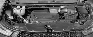
Chrysler Pacifica (2021 - 2024) - fuse box location - engine compartment
Chrysler Pacifica (2021 – 2024) – fuse box location – engine compartment

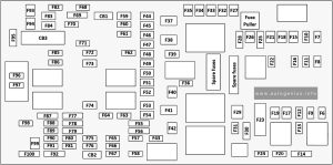
Fuse box diagram

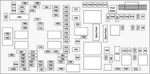
Chrysler Pacifica (2021 - 2024) - fuse box diagram - engine compartment
Chrysler Pacifica (2021 – 2024) – fuse box diagram – engine compartment

Assignment of the fuses in the engine compartment (2021-2024)

Amps Description
F06 Not Used
F07 25A Clear Ignition Coil / Fuel Injector
F08 Not Used
F09 25A Clear Amplifier / Active Noise Control
F10 Not Used
F11 Not Used
F12 5A Tan Battery Sensor (IBS)
F13 10A Red ECM (S)
F14 10A Red ECM
F15 40A Green CBC / Power Locks
F16 20A Yellow ECM
F17 30A Pink Starter
F18 40A Green CBC / EXT LIGHTS
F19 25A Clear 2nd Row Folding Seats Solenoid (Left)
F20 10A Red A/C Compressor Clutch
F21 25A Clear 2nd Row Folding Seat Solenoid (Right)
F22 Not Used
F23 Not used
F24 20A Yellow RR Wiper
F25 10A Red Hands Free Dr Mod / Active Grille Shutter / Pwr Mirror / VRM
F26 40A Green Front HVAC Blower Motor
F27 25A Clear RR Slide Door Module – Right
F28 10A Red Diagnostic Port / USB+(IP) / Video USB Port / Overhead DVD Player (Aftermarket)
F29 Not Used
F30 15A Blue Media HUB/ Power Lumbar
F31 Not Used
F32 20A Blue ECM
F33 30A Pink Power Liftgate Module
F34 25A Clear RR Door Module – Left
F35 25A Clear Sunroof
F36 Not Used
F37 40A Green CBC / Exterior Lights
F38 60A Yellow Vacuum Cleaner
F39 25A Clear Rear HVAC Blower Motor
F40 Not Used
F41 Not Used
F42 40A Green Folding Seat Module
F43 20A Yellow Fuel Pump Motor
F44 30A Pink CBC / Interior Lights
F45 30A Pink Power Inverter
F46 30A Pink Driver Door Module
F47 30A Pink Passenger Door Module
F48 Not Used
F49 25A Clear RR Sliding Door Module – Left
F50 25A Clear RR Door Module – Right
F51 30A Pink Front Wiper
F52 30A Pink Brake Vacuum Pump
F53 Not Used
F54 40A Green ESP-ECU And Valves
F55 15A Blue Radio Frequency HUB / Keyless Ignition System (KIN) / ESL / DVD
F56 10A Red Front and Rear HVAC Control Module / Occupant Classification Module (OCM) / Electronic Steering Lock (ESL) / ESP / ESC
F57 Not Used
F58 10A Red Drive Train Control Mod / Power Transfer Unit
F59 30A Pink Trailer Tow Receptacle
F60 20A Yellow Rear Cargo Pwr Outlet
F61 20A Yellow Trailer Tow Right Stop/Turn
F62 20A Yellow Power Transfer Unit
F63 20A Yellow Trailer Tow Left Stop/Turn
F64 15A Blue HID Headlamp (Right)
F65 Not Used
F66 15A Blue Cluster
F67 10A Red Haptic Lane Feedback Module (HALF) / Parktronics System (PTS) / Drivers Assist System Module (DASM)
F68 Not Used
F69 Not Used
F70 Not Used
F71 20A Yellow Horn
F72 10A Red Heated Mirror
F73 30A Pink Rear Defroster
F74 20A Blue Trailer Tow Backup Lights
F75 5A Tan Overhead Console / RR Center Stack
F76 20A Yellow Uconnect / Center Display / Telematics
F77 10A Red RR Entertainment / Media HUB / USB (S) / Rain Sensor/ Sunroof / RR View Mirror / Overhead DVD Player / INT Monitoring Camera / Wireless Charging Pad
F78 15A Blue TCM (ZF) / E-Shifter / Cluster
F79 10A Red ICS / HVAC / SCCM/ EPB SW
F80 Not Used
F81 Not Used
F82 Not Used
F83 20A Blue TT Park Lights
F83 30A Pink Headlamp Washer Pump
F84 30A Pink Drive Train Control MOD
F85 20A Yellow Cigar Lighter
F86 Not Used
F87 Not Used
F88 20A Yellow Front Heated Seats
F89 20A Yellow Rear Heated Seats
F90 Not Used
F91 15A Blue Front Ventilated Seats / Heated Steering Wheel
F92 5A Tan Security Gateway
F93 Not Used
F94 40A Green ESC Motor Pump
F95A 10A Red USB Charge Port – ACC/RUN
F95B 10A Red Selectable Fuse Location – USB IP (Direct) B+
F96 10A Red Airbag
F97 10A Red Airbag
F98 15A Blue HID Headlamp (Left)
F99 30A Pink Trailer Tow Elect Brake Module
F100 10A Red Headlamp Level / RR Camera / Blindspot/ Humidity SNSR / In Car Temp SNSR / Headlamp SW
CB1 25A Circuit Breaker Power Seats (Driver)
CB2 25A Circuit Breaker Power Seats (Pass) (30 Amp mini fuse is substituted for 25 Amp Circuit Breaker)
CB3 25A Circuit Breaker FRT PWR Window W/O Door Nodes + RR PWR Window Lockout

WARNING: Terminal and harness assignments for individual connectors will vary depending on vehicle equipment level, model, and market.

Chrysler Voyager (2020 – 2024) – fuse box diagram

Chrysler Voyager (2020 – 2024) – fuse box diagram


Year of production: 2020, 2021, 2022, 2023


This article covers the sixth-generation Chrysler Voyager, produced from 2020 to the present. It includes fuse box diagrams for Chrysler Voyager models from 2020 through 2024, provides details on the location of the fuse panels inside the vehicle, and explains the function of each fuse (fuse layout).

Engine compartment fuse box

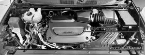
Fuse Box Location

The Power Distribution Center (PDC) is located in the engine compartment near the battery. Remove the cover by unlatching the two locks located at each side of the PDC cover, avoid using screwdrivers or any other tool to remove the cover, since they may apply excessive force and result in a broken/damaged part.


Chrysler Voyager (2020 - 2024) - fuse box location - engine compartment
Chrysler Voyager (2020 – 2024) – fuse box location – engine compartment

Fuse Box Diagram

Chrysler Voyager (2020 - 2024) - fuse box diagram - engine compartment
Chrysler Voyager (2020 – 2024) – fuse box diagram – engine compartment


Assignment of the fuses in the PDC (2020-2024)

Amps Description
F06 Not Used
F07 25A Clear Ignition Coil / Fuel Injector
F08 Not Used
F09 25A Clear Amplifier / Active Noise Control
F10 Not Used
F11 Not Used
F12 5A Tan Battery Sensor (IBS)
F13 10A Red 2020-2021: ECM (ESS Only)
2022-2024: ECM (S)
F14 10A Red ECM
F15 40A Green CBC Feed #3 (Power Locks)
F16 20A Yellow ECM
F17 30A Pink Starter
F18 40A Green CBC Feed #4 (Exterior Lighting #1)
F19 25A Clear 2nd Row Folding Seats Solenoid LT
F20 10A Red A/C Compressor Clutch
F21 25A Clear 2nd Row Folding Seat Solenoid RT
F22 Not Used
F23 Not used
F24 20A Yellow RR Wiper
F25A 10A Red 2020-2021: Handsfree LT & RT RR Door Release Mod
F25B 10A Red 2020-2021: Active Grill Shutter / PWR Mirror
F25 10A Red 2022-2024: Hands-free Door Mod / Active Grill Shutter / PWR Mirror / VRM
F26 40A Green Front HVAC Blower Motor
F27 25A Clear RR Slide Door Module – RT
F28A 10A Red 2020-2021: Diagnostic Report
F28B 10A Red 2020-2021: USB + AUX Port / Video USB Port
F28 10A Red 2022-2024: Diagnostic Port / USB+ (IP) / Video USB Port / Overhead DVD Player (Aftermarket)
F29 Not Used
F30A 15A Blue 2020-2021: Media HUB 1&2
F30B 15A Blue 2020-2021: PWR Lumbar SW
F30 15A Blue 2022-2024: Media HUB / PWR Lumbar
F31 Not Used
F32 20A Blue ECM
F33 30A Pink Power Liftgate Module
F34 25A Clear RR Door Module – LT
F35 25A Clear Sunroof Control Module
F36 Not Used
F37 40A Green 2020-2021: CBC Feed #4 (Exterior Lighting #2)
2022-2024: CBC / Exterior Lights
F38 60A Yellow Vacuum Cleaner
F39 25A Clear Rear HVAC Blower Motor
F40 Not Used
F41 Not Used
F42 40A Green Folding Seat Module
F43 20A Yellow Fuel Pump Motor
F44 30A Pink 2020-2021: CBC Feed #1 (Interior Lights)
2022-2024: CBC / Interior Lights
F45 30A Pink Power Inverter
F46 30A Pink Driver Door Module
F47 30A Pink Passenger Door Module
F48 Not Used
F49 25A Clear RR Sliding Door Module – LT
F50 25A Clear RR Door Module – RT
F51 30A Pink Front Wiper
F52 30A Pink Brake Vacuum Pump
F53 Not Used
F54 40A Green ESP-ECU And Valves
F55A 15A Blue 2020-2021: Radio Frequency HUB / Keyless Ignition System (KIN) / (Electronic Steering Lock-BUX ONLY)
F55B 15A Blue 2020-2021: DVD / Video Routing Module (VRM
F55 15A Blue 2022-2024: RF HUB/ KIN / ESL / DVD
F56A 10A Red 2020-2021: Front and Rear HVAC Control Module / Occupant Classification Module (OCM) / Electronic Steering Lock (ESL)
F56B 10A Red 2020-2021: ESP/ESC
F56 10A Red 2022-2024: Front & Rear HVAC Control / OCM / ESL / ESP / ESC
F57 Not Used
F58 10A Red Drive Train Control Mod / Power Transfer Unit – If Equipped
F59 30A Pink Trailer Tow Receptacle – If Equipped
F60 20A Yellow Rear Cargo APO
F61 20A Yellow Trailer Tow Right Stop/Turn – If Equipped
F62 Not Used
F63 20A Yellow Trailer Tow Left Stop/Turn – If Equipped
F64 15A Blue RT HID Headlamp
F65 Not Used
F66 15A Blue 2020-2021: Instrument Panel Cluster (IPC) / SGW
2022-2024: Cluster
F67 10A Red Haptic Lane Feedback Module (HALF) / Parktronics System (PTS) / Drivers Assist System Module (DASM)
F68 Not Used
F69 Not Used
F70 Not Used
F71 20A Yellow Horn
F72 10A Red Heated Mirrors – If Equipped
F73 30A Pink Rear Defroster (EBL)
F74 20A Blue Trailer Tow Backup
F75 5A Tan Overhead Console / RR ISC
F76 20A Yellow Uconnect / Center Display / Telematics
F77A 10A Red 2020-2021: RR Entertainment Screen 1 & 2 / Media HUB 1 & 2 / 3rd Row USB Charge 0nly / 2nd Row USB Charge Only / Vaccum Cleaner SW / 3rd Row Recline ST SW / LT & RT Stow N Go SW / LT & RT Sliding Door SW Backlight
F77B 10A Red 2020-2021: Rain Sensor / Sunroof / CRVMM
F77 10A Red 2022-2024: RR Entertainment / Media Hub / USB (S) / Rain Sensor / Sunroof / RR View Mirror / Overhead DVD Player / Int Monitoring Camera / Wireless Charging Pad
F78A 15A Blue 2020-2021: Transmission Control Module (TCM) / E-Shifter
F78B 15A Blue 2020-2021: Instrument Cluster
F78 15A Blue 2022-2024: TCM (ZF) / E-Shifter / Cluster
F79 10A Red 2020-2021: ICS / Front And Rear HVAC / SCCM / EPB
2022-2024: ICS / HVAC / EPB SW / Strg Column Cntrl
F80 Not Used
F81 Not Used
F82 Not Used
F83 20A Blue TT Park Lights – If Equipped
30A Pink Headlamp Washer Pump – If Equipped
F84 30A Pink Drive Train Control MOD – If Equipped
F85 20A Yellow Cigar Lighter
F86 Not Used
F87 Not Used
F88 20A Yellow Front Heated Seats
F89 20A Yellow Rear Heated Seats
F90 Not Used
F91 15A Blue Front Ventilated Seats / Heated Steering Wheel
F92 5A Tan Security Gateway
F93 Not Used
F94 40A Green ESC Motor Pump
F95A 10A Red USB Charge Port – ACC RUN
F95B 10A Red Selectable Fuse Location – USB IP (Direct) B+
F96 10A Red Occupant Restraint Controller (ORC) (Airbag)
F97 10A Red Occupant Restraint Controller (ORC) (Airbag)
F98 15A Blue Left HID Headlamp
F99 30A Pink Trailer Tow Module – If Equipped
F100A 10A Red 2020-2021: AHLM
F100B 10A Red 2020-2021: Rear Camera / LBSS / RBSS / CVPM / Humidity Sensor / ln Vehicle Temperature Sensor
F100 10A Red 2022-2024: Headlamp Level / RR Camera / Blindspot / Humidity Snsr / In Car Temp Snsr / Headlamp SW
CB1 25A Circuit Breaker Power Seats (Driver)
CB2 25A Circuit Breaker Power Seats (Pass)
30 Amp mini fuse is substituted for 25 Amp Circuit Breaker.
CB3 25A Circuit Breaker FRT PWR Window W/O Door Nodes + RR PWR Window Lockout


WARNING: Terminal and harness assignments for individual connectors will vary depending on vehicle equipment level, model, and market.
Chrysler Neon (1994 – 1999) – fuse and relay box diagram

Chrysler Neon (1994 – 1999) – fuse and relay box diagram

Year of production: 1994, 1995, 1996, 1997, 1998, 1999


The Chrysler Neon, also known as the Dodge Neon in some markets, was a compact car produced by Chrysler Corporation from 1994 to 2005. It was initially marketed under both the Dodge and Plymouth brands in North America and as the Chrysler Neon in international markets.


First Generation (1994–1999), Second Generation (2000–2005), Dodge Neon SRT-4 (2003–2005)


Passenger Compartment Fuse Box

Fuse box location

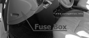
The fuse panel is located behind the cover on the driver’s side of the dashboard.

Chrysler Neon (1994 - 1999) - fuse and relay location - passenger compartment
Chrysler Neon (1994 – 1999) – fuse and relay location – passenger compartment


Fuse box Diagram

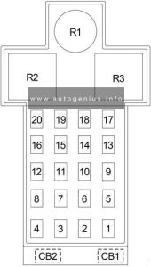
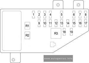
Chrysler Neon (1994 - 1999) - fuse and relay diagram - passenger compartment
Chrysler Neon (1994 – 1999) – fuse and relay diagram – passenger compartment


Assignment of fuses in the passenger compartment

No.
A
Circuit Protected
1 15 Cigar Lighter/Power Outlet
2 15 Headlamp Switch (Park Lamp, Tail Lamp, License Lamp, Radio, Front Fog Lamp Switch, Remote Keyless Entry Module (’98-’99))
3 20 Door Lock Switch, Remote Keyless Entry Module (’98-’99), Immobilizer (’98-’99)
4 10 Fog Lamp Switch
5 10 ’95-’97: A/C Cycling Switch, Back-Up Lamp (Back-Up Lamp Switch M/T), Park/Neutral Position Switch (A/T), Rear Window Defogger Switch
10 ’98-’99 (LHD): Airbag Control Module
10 ’98-’99 (RHD): A/C Cycling Switch, Back-Up Lamp (Back-Up Lamp Switch M/T), Park/Neutral Position Switch (A/T), Rear Window Defogger Switch, High Speed Warning Module
6 10 Turn Signal/Hazard
7 25 A/C Heater Blower Motor
8 10 ’95-’97: Airbag Control Module
10 ’98-’99 (LHD): A/C Cycling Switch, Back-Up Lamp (Back-Up Lamp Switch M/T), Park/Neutral Position Switch (A/T), Rear Window Defogger Switch, High Speed Warning Module
10 ’98-’99 (RHD): Airbag Control Module
9 4 ’95-’97: Instrument Cluster, Radio, Ash Receiver Lamp, Rear Window Defogger Switch, “PRNDL” Lamp, Rear Fog Lamp Switch, A/C Heater Control Switch, Headlamp Leveling Switch
10 ’98-’99 (LHD): Airbag Control Module
4 ’98-’99 (RHD): Instrument Cluster, Radio, Ash Receiver Lamp, Rear Window Defogger Switch, “PRNDL” Lamp, Rear Fog Lamp Switch, A/C Heater Control Switch, Headlamp Leveling Switch
10 15 Powertrain Control Module, Air Conditioner Compressor Clutch Relay, ABS, Vapor Canister Leak Detector, Torque Converter Clutch Solenooid (A/T), Duty Cycle EVAP/Purge Solenoid, ABS Relay Box, EGR Transducer Solenoid, ABS Warning Lamp Relay
11 5 Instrument Cluster, Daytime Running Lamp Module (’98-’99), Remote Keyless Entry Module (’98-’99), Immobilizer (’98-’99)
12 10 ’95-’97: Airbag Control Module
4 ’98-’99 (LHD): Instrument Cluster, Radio, Ash Receiver Lamp, Rear Window Defogger Switch, “PRNDL” Lamp, Rear Fog Lamp Switch, A/C Heater Control Switch, Headlamp Leveling Switch
10 ’98-’99 (RHD): Airbag Control Module
13  –
14 20 Sunroof
15 20 Wiper Motor, Wiper/Washer Switch, Intermittent Wiper/Washer Switch, Cigar Lighter Relay
16 10 Radio
17 10 Left Headlamp, Left/Right Headlamp Leveling Motor
18 10 Right Headlamp
19  –
20  –
Circuit Breaker
CB1 30 Power Window, Power Window
CB2  –
Relay
R1 ’98-’99 (LHD): Time Delay
R2 ’95-’97: Cigar Lighter
’98-’99 (LHD): Combination Flasher
’98-’99 (RHD): Cigar Lighter
R3 ’95-’97: Combination Flasher
’98-’99 (LHD): Time Out
’98-’99 (RHD): Combination Flasher


Engine Compartment Fuse Box

Fuse box location

Chrysler Neon (1994 - 1999) - fuse and relay location - engine compartment
Chrysler Neon (1994 – 1999) – fuse and relay location – engine compartment


Fuse box diagram

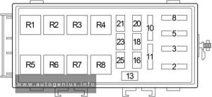
Chrysler Neon (1994 - 1999) - fuse and relay diagram - engine compartment
Chrysler Neon (1994 – 1999) – fuse and relay diagram – engine compartment


Assignment of fuses and relay in the engine compartment

No.
A
Protected Component
2 40 Ignition Switch (Fuse (Passenger Compartment): “5”, “6”, “7”, “8”, “CB1”)
3 40 Headlamp Switch, Fuse (Passenger Compartment): “1”, “3”, “4”
5 30 Solid State Fan Relay (Radiator Fan)
8 30 Rear Window Defogger
10 40 ABS Relay Box
11 30 Starter Relay, Ignition Switch (Clutch Pedal Position Switch (M/T), Fuse (Passenger Compartment): “10”, “11”, “12”, “14”, “15”, “16”)
13 10 Dome Lamp, Trunk Lamp, Underhood Lamp, Instrument Cluster, Radio, Glove Box Lamp, Map/Reading Lamp, Visor/Vanity Lamp, Power Mirror Switch, High Speed Warning Module (’98-’99), Time Delay Relay (’98-’99), Time Out Relay (’98-’99)
16 20 Fog Lamp Relay, Rear Fog Lamp Switch
18 10 ’95-’97: Air Conditioner Compressor Clutch Relay
20 ’98-’99: Air Conditioner Compressor Clutch Relay, ABS
20 10 Turn Signal/Hazard
21 20 Fuel Pump Relay, Auto Shut Down Relay (Fuel Injectors, Ignition Coil Pack, Powertrain Control Module, Generator, Data Link Connector, Oxygen Sensors, Capacitor, Noise Suppressor)
23 15 Horn Relay
25 15 Stop Lamp Switch
Relay
R1  –
R2 Fuel Pump
R3 Auto Shut Down
R4 Horn
R5 Fog Lamp
R6 ABS Warning Lamp
R7 Air Conditioner Compressor Clutch
R8 Starter

WARNING: Terminal and harness assignments for individual connectors will vary depending on vehicle equipment level, model, and market.
Chrysler Cirrus (1995 – 2000) – fuse and relay box diagram

Chrysler Cirrus (1995 – 2000) – fuse and relay box diagram

Year of production: 1995, 1996, 1997, 1998, 1999, 2000


The Chrysler Cirrus is a mid-size sedan that was produced by Chrysler from 1995 to 2000. Part of Chrysler’s “Cloud Car” series, the Cirrus shared its platform with the Dodge Stratus and Plymouth Breeze, with each model offering slightly different features and trim levels. The Cirrus was designed to offer a balance of style, performance, and comfort in the competitive mid-size sedan market of the 1990s.

The Chrysler Cirrus was a stylish, comfortable, and reasonably well-equipped sedan for its time. It offered a good blend of power (particularly with the V6 engine), a smooth ride, and modern design cues. While it is no longer in production, the Cirrus remains a memorable part of Chrysler’s history in the mid-size sedan segment.


Passenger Compartment Fuse Box

Fuse Box Location

Chrysler Cirrus (1995 - 2000) - fuse and relay location - passenger compartment
Chrysler Cirrus (1995 – 2000) – fuse and relay location – passenger compartment


Fuse Box Diagram

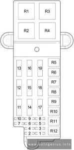
Chrysler Cirrus (1995 - 2000) - fuse and relay diagram - passenger compartment
Chrysler Cirrus (1995 – 2000) – fuse and relay diagram – passenger compartment


Assignment of fuses in the instrument panel

No.
A
Protected Component
1 30 Blower Motor
2 20 Convertible: Right Headlamp (High Beam), Daytime Running Lamp Module
10 Right Headlamp (High Beam), Daytime Running Lamp Module
3 20 Convertible: Left Headlamp (High Beam)
10 Left Headlamp (High Beam)
4 15 Back-Up Lamp (Back-Up Lamp Switch (M/T), Transmission Range Sensor (A/T)), Power Top Relay (Convertible), Daytime Running Lamp Module, Power Door Lock Switch, Power Mirror Switch, Automatic Day/Night Mirror, Steering Proportional Steering Module
5 10 Dome Lamp, Data Link Connector, Power Antenna, Overhead Map Lamp, Trunk Lamp, Traveler, Body Control Module, Radio, Glove Box Lamp, Visor/Vanity Lamp, Universal Garage Door Opener, Automatic Day/Night Mirror, Illuminated Entry Relay, Courtesy Lamp, Power Door Lock Switch, Door Arm/Disarm Switch, Key-In Halo Lanp, Sunroof Control Module
6 10 Heated Mirror, A/C Heater Control
7 20 ’98-’00: Instrument Cluster, Headlamp Switch
15 ’95-’97: Headlamp Switch
8 20 Cigar Lighter/Power Outlet, Horn Relay
9 15 Body Control Module
10 20 Rear Fog Lamp Switch, Daytime Running Lamp Module
11 10 Body Control Module, Instrument Cluster, Autostick Switch, Transmission Control Module
12 10 Left Headlamp (Low Beam), Daytime Running Lamp Module
13 20 Right Headlamp (Low Beam), Front Fog Lamp Switch
14 10 Radio
15 10 Combination Flasher, Seat Belt Control Module (Convertible), Intermittent Wiper Relay, Wiper (High/Low) Relay, Rear Window Defogger Relay
16 10 Airbag Control Module
17 10 Airbag Control Module
Circuit Breaker
18 20 Power Seat Switch, Decklid Release Relay
19 20 Power Window, Master Power Window Switch, Window Timer Module, Sunroof Control module
Relay
R1 Headlamp Delay
R2 Horn
R3 Rear Window Defogger


Engine Compartment Fuse Box

Fuse Box Location

Chrysler Cirrus (1995 - 2000) - fuse and relay location - engine compartment
Chrysler Cirrus (1995 – 2000) – fuse and relay location – engine compartment


Fuse Box Diagram

Chrysler Cirrus (1995 - 2000) - fuse and relay diagram - engine compartment
Chrysler Cirrus (1995 – 2000) – fuse and relay diagram – engine compartment


Assignment of fuses in the engine compartment

No.
A
Protected Component
1 10 Oxygen Sensor Downstream
2 20 ABS
3 20 Transmission Control Module, Transmission Control Relay
4 20 Stop Lamp Switch, Fuse (Passenger Compartment): “5”
5 20 Automatic Shut Down Relay (Fuel Injectors, Ignition Coil Pack (2.0L and 2.4L), Noise Suppressor (2.0L and 2.4L), Generator, Oxygen Sensor Upstream, Distributor (2.5L) EGR Solenoid, Fuse: “1”), Powertrain Control Module
6 20 Combination Flasher, Sentry Key Immobilizer Module
7 10 Ignition Switch (Fuse (Passenger Compartment): “11”)
8 20 Starter Relay, Fuel Pump Relay, Ignition Switch (Body Control Module, Clutch Interlock Switch (M/T), Transmission Control Module (EATX), Fuse (Passenger Compartment): “14”, “15”, “17”, Fuse (Engine Compartment): “9”, “10”)
9 10 Air Conditioner Compressor Clutch Relay, Radiator Fan (High Speed) Relay, Radiator Fan (Low Speed) Relay, Fuel Pump Module, Instrument Cluster, Sentry Key Immobilizer Module, Brake Shift Interlock Solenoid
10 10 Fuel Pump Relay, Powertrain Control Module, ABS
11 20 Convertible: Seat Belt Control Module
12 40 Rear Window Defogger Relay
13 40 ABS
14 40 Fuse (Passenger Compartment): “7”, “8”
15 40 Headlamp Switch, Headlamp Delay Relay (Body Control Module, Headlamp Switch, Fuse (Passenger Compartment): “12”, “13”), Fuse (Passenger Compartment): “9”, “10””18″
16 40 Ignition Switch (Fuse (Passenger Compartment): “1”, “4”, “16”, “19”)
17 40 Convertible: Power Top Up/Down Relays
18 40 Intermittent Wiper Relay (Wiper (High/Low) Relay)
19 40 Air Conditioner Compressor Clutch Relay, Radiator Fan (High Speed) Relay, Radiator Fan (Low Speed) Relay
Relay
R1 Radiator Fan (High Speed)
R2 Automatic Shut Down
R3 Radiator Fan (Low Speed)
R4 Starter
R5  –
R6 Air Conditioner Compressor Clutch
R7 Convertible: Power Tow
R8 Intermittent Wiper
R9 Wiper (High/Low)
R10 Fuel Pump
R11 Transmission Control
R12  –

WARNING: Terminal and harness assignments for individual connectors will vary depending on vehicle equipment level, model, and market.