Opel Ampera-e (2017 – 2019) – fuse and relay box diagram
Year of production: 2017, 2018, 2019, 2020
The Opel Ampera-e, a battery-electric subcompact hatchback, was manufactured between 2017 and 2019. This article provides fuse box diagrams for the 2017, 2018, and 2019 models, along with details on the fuse panel locations within the vehicle and the specific functions of each fuse (fuse layout).
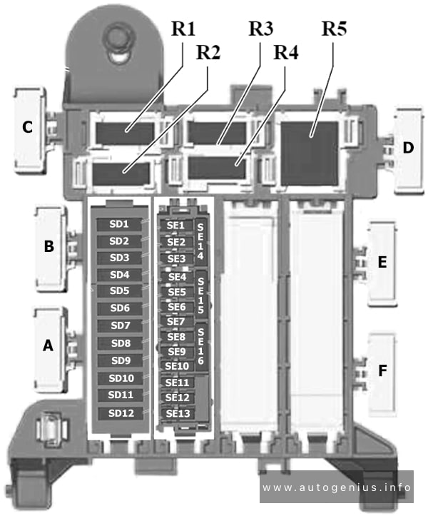
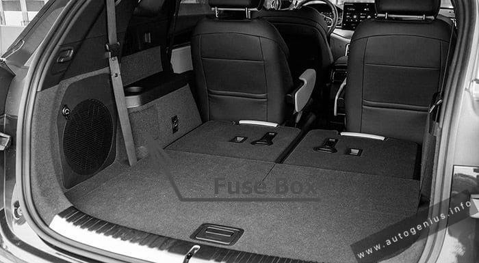
Passenger Compartment Fuse Box
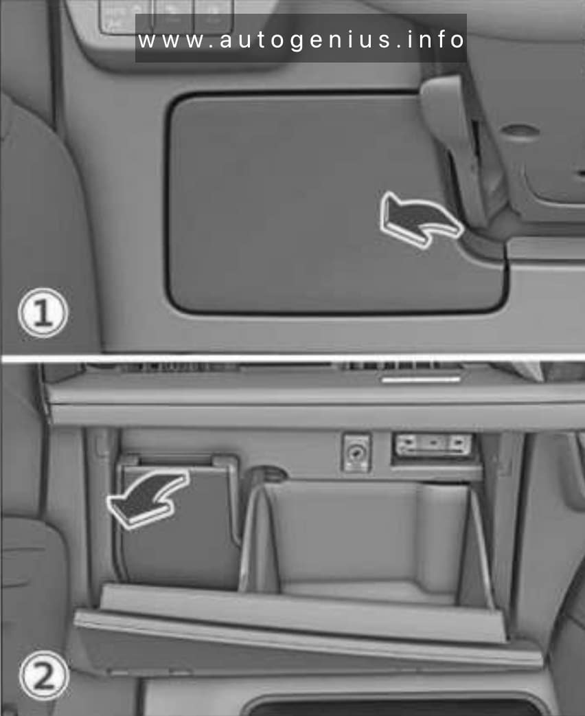
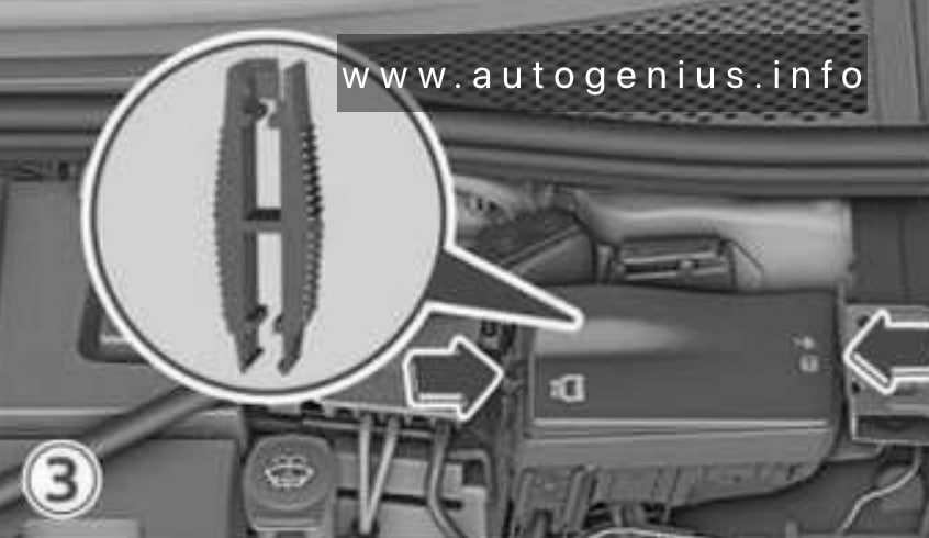
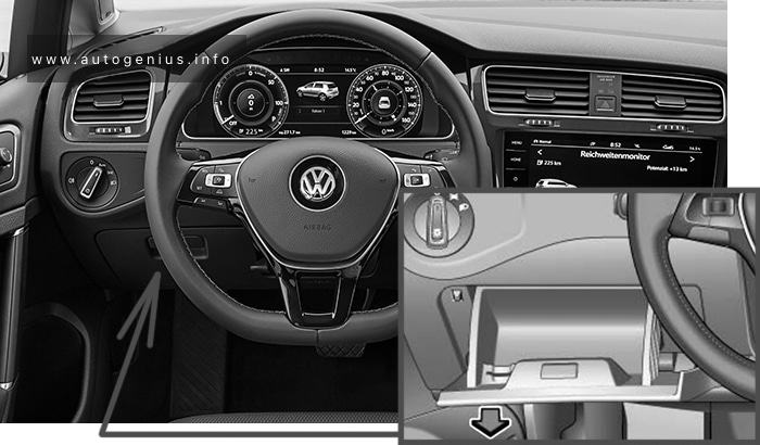
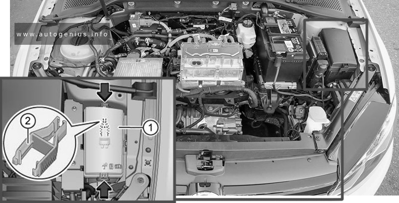
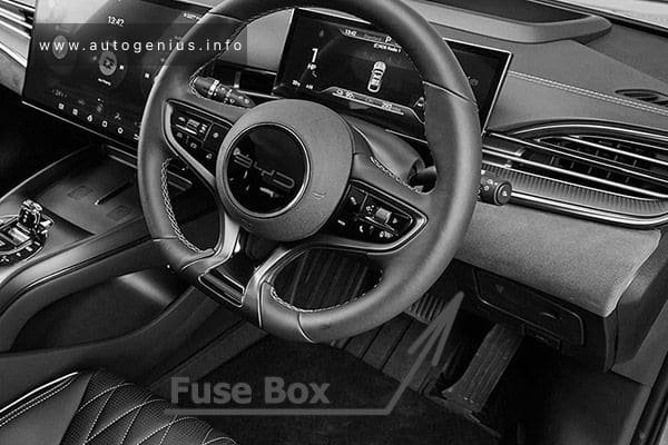
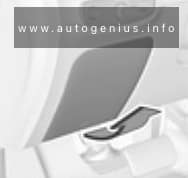
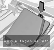
Fuse Box Location
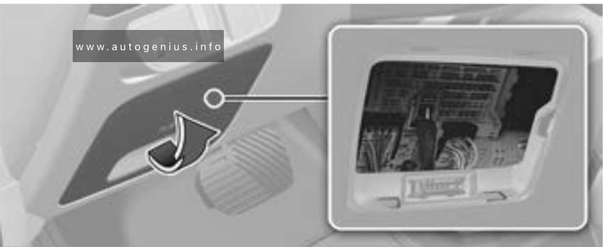
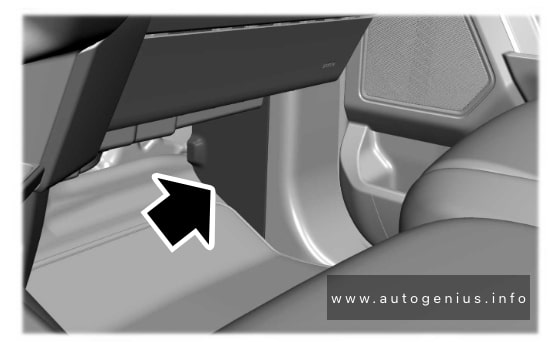
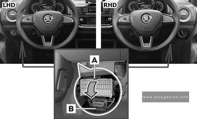
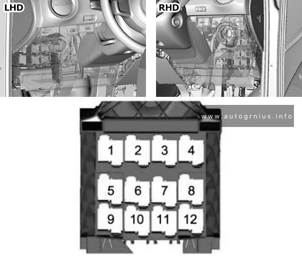
The fuse box is located on the driver’s side behind a cover in the instrument panel.
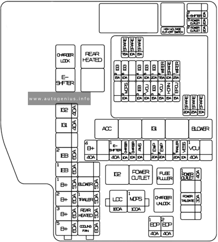
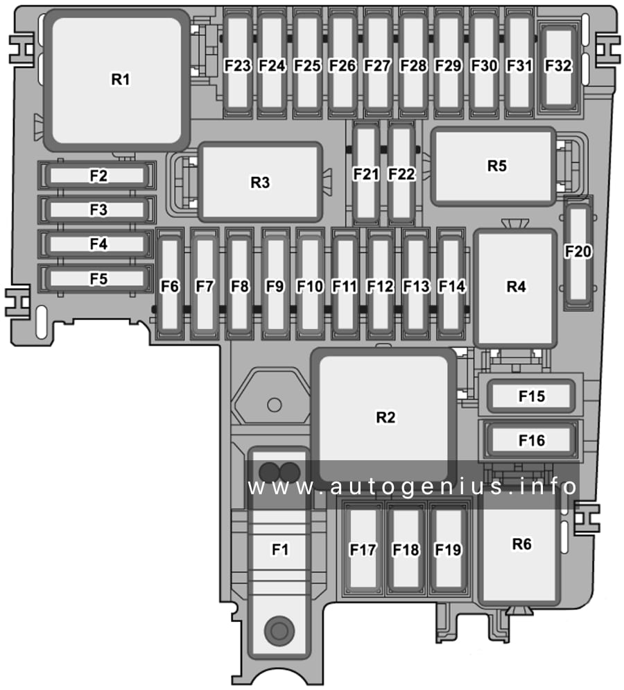
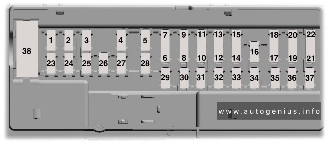
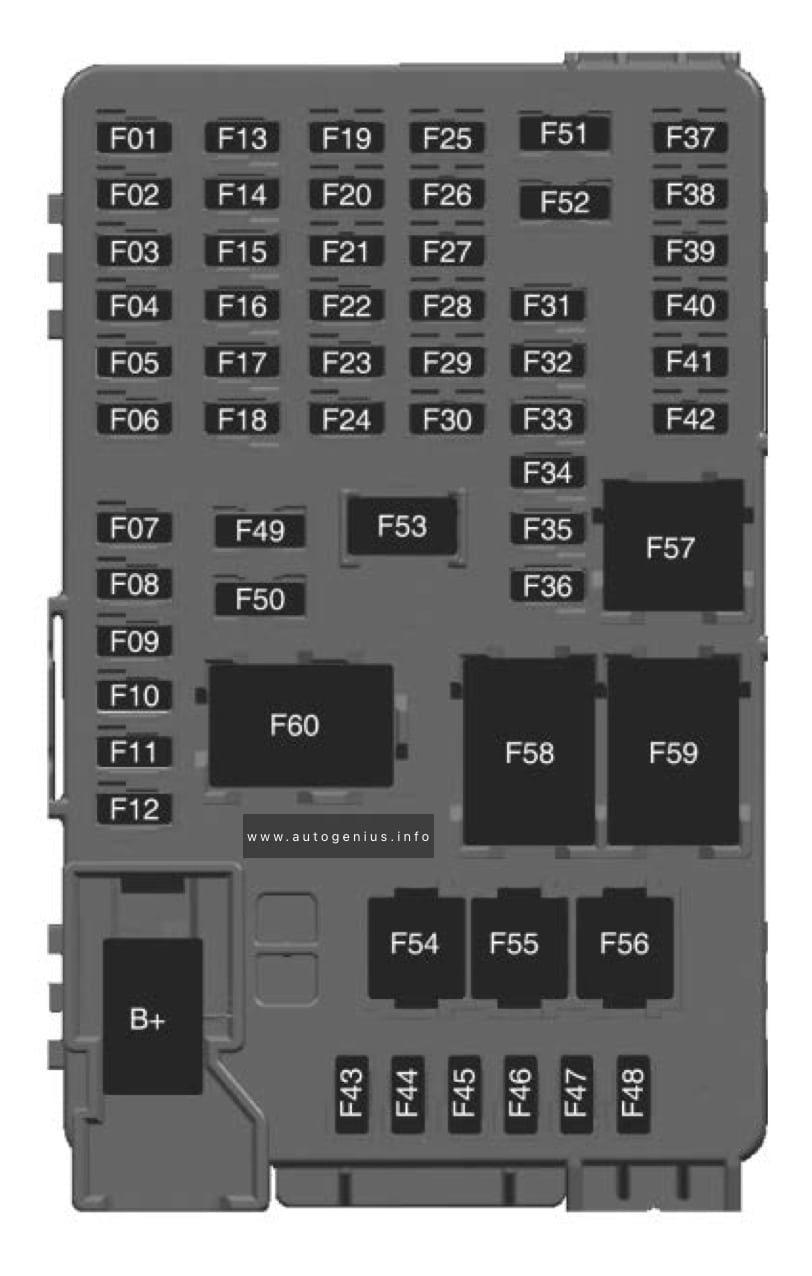
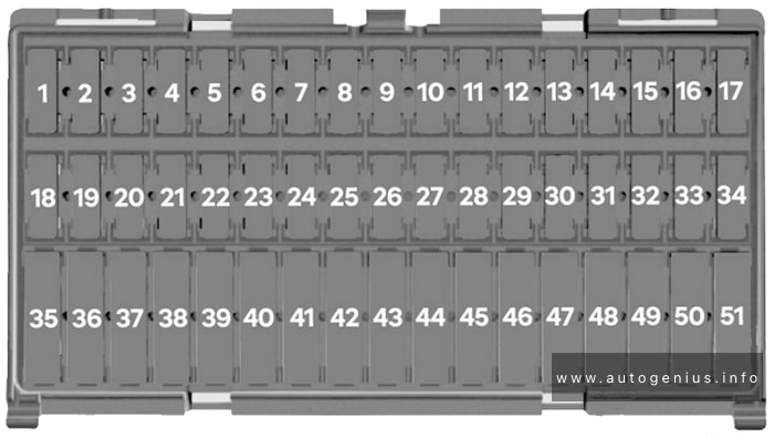
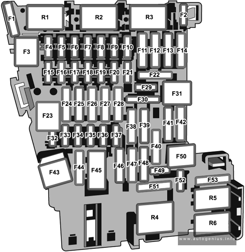
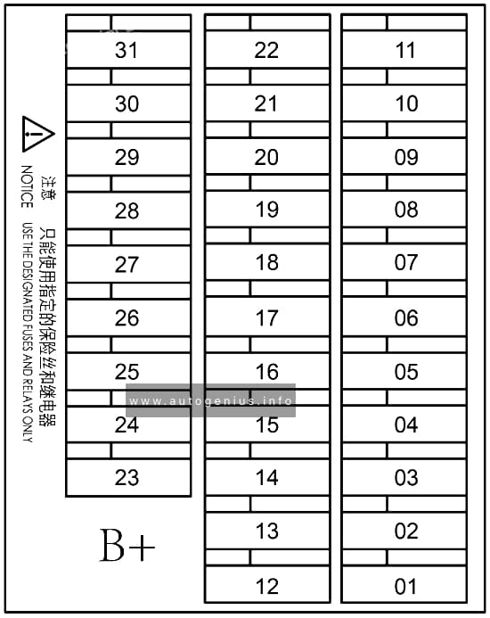
Fuse Box Diagram
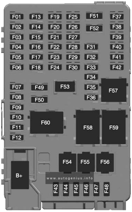
Assignment of the fuses in the passenger compartment
| № | Usage |
|---|---|
| 1 | Video processing module |
| 2 | Indicator light solar sensor |
| 3 | Side blind zone alert |
| 4 | Passive entry, passive start |
| 5 | Central gateway module |
| 6 | Body control module 4 |
| 7 | Body control module 3 |
| 8 | Body control module 2 |
| 9 | Body control module 1 |
| 10 | Trailer interface module 1 |
| 11 | Amplifier |
| 12 | Body control module 8 |
| 13 | Data link connector 1 |
| 14 | Automatic parking assist |
| 15 | 2016-2017: Data link connector 2 |
| 16 | Single power inverter module 1 |
| 17 | Body control module 6 |
| 18 | Body control module 5 |
| 19 | – |
| 20 | – |
| 21 | – |
| 22 | – |
| 23 | USB |
| 24 | Wireless charging module |
| 25 | Reflected LED alert display |
| 26 | Heated steering wheel |
| 27 | – |
| 28 | Instrument cluster 2 |
| 29 | Trailer interface module 2 |
| 30 | Headlight levelling device |
| 31 | OnStar |
| 32 | – |
| 33 | Heating, ventilation, and air conditioning module |
| 34 | – |
| 35 | Instrument panel cluster 1 |
| 36 | Regen on demand / Radio |
| 37 | – |
| 38 | – |
| 39 | – |
| 40 | – |
| 41 | – |
| 42 | – |
| 43 | Body control module 7 |
| 44 | Sensing and diagnostic module |
| 45 | Front camera module |
| 46 | Vehicle integration control module |
| 47 | Single power inverter module 2 |
| 48 | Electric steering column lock |
| 49 | Auxiliary jack |
| 50 | Steering wheel controls |
| 51 | Steering wheel controls backlighting |
| 52 | Smartphone remote function module |
| 53 | Auxiliary power outlet |
| 54 | – |
| 55 | Logistic |
| 56 | – |
| 57 | – |
| 58 | Logistics relay |
| 59 | – |
| 60 | Accessory/Retained accessory power relay |
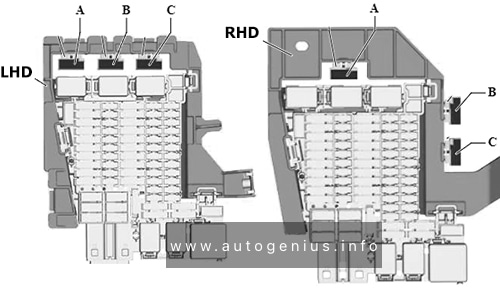
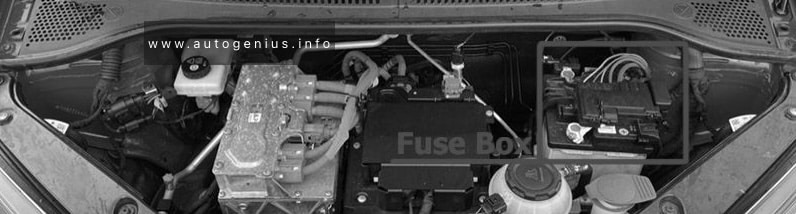
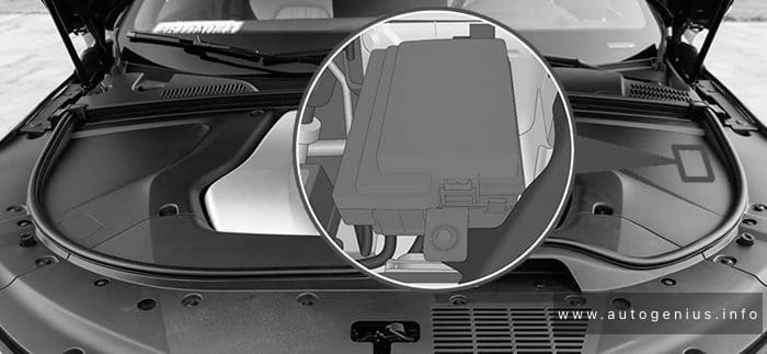
Engine compartment fuse box
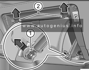
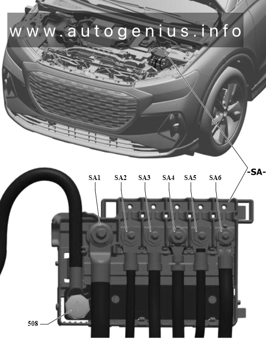
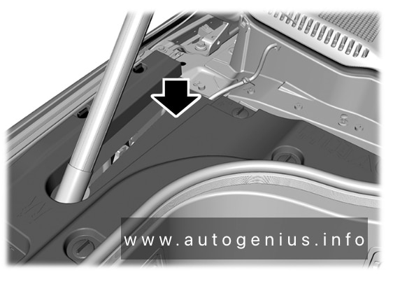
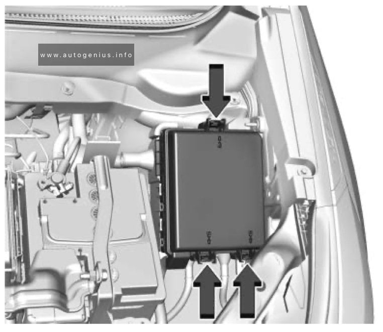
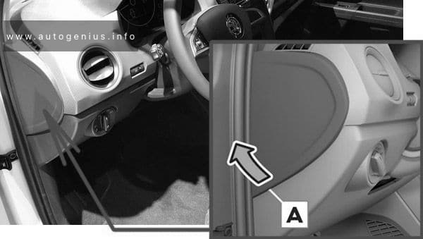
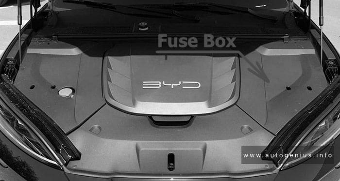
Fuse Box Location
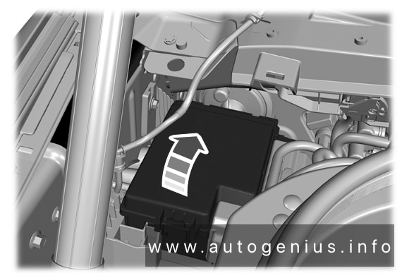
The fuse box is located at the left front side of the engine compartment.
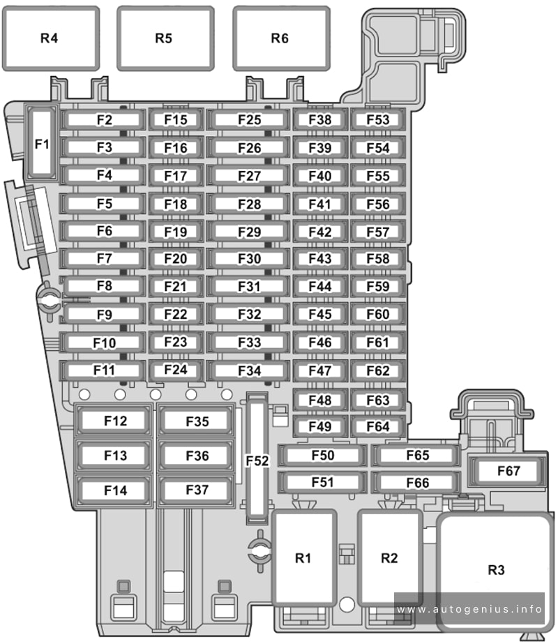
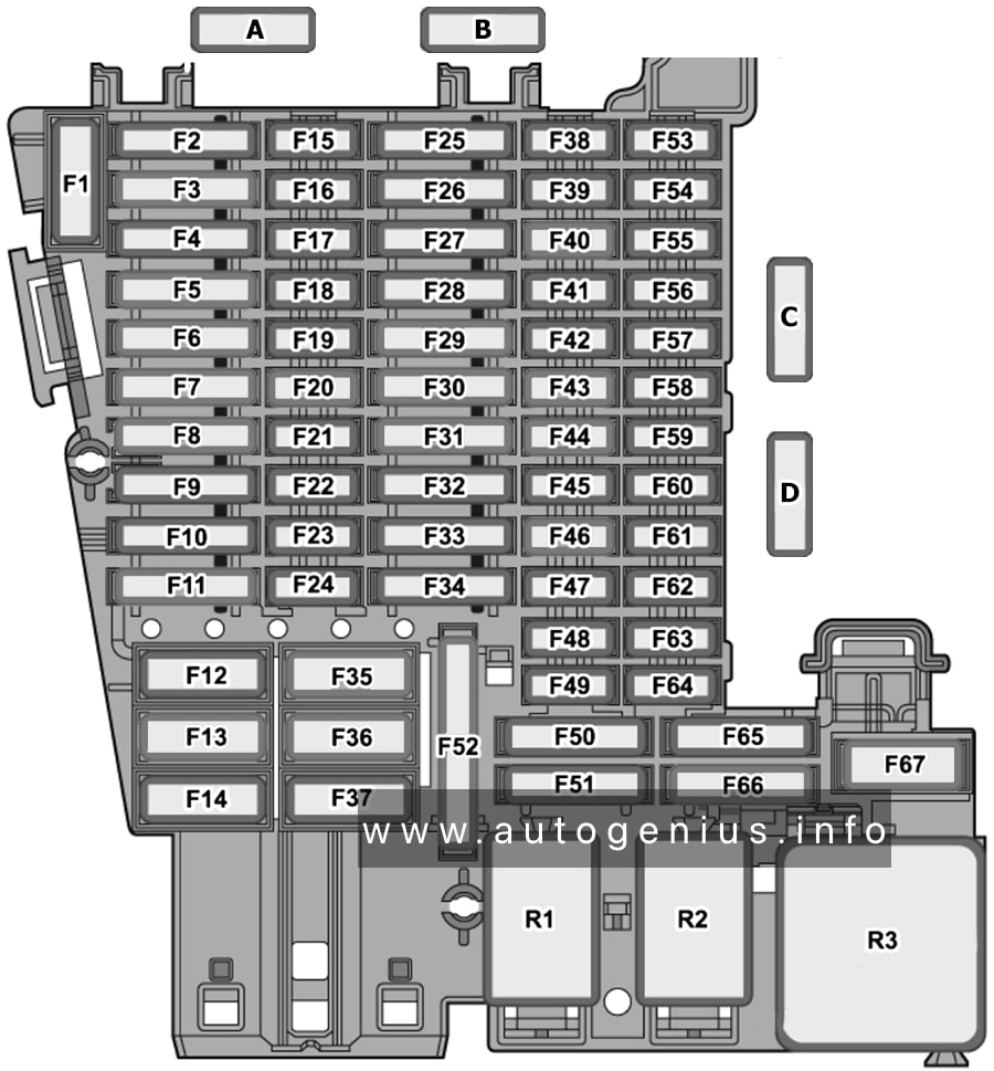
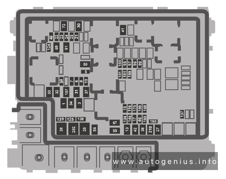
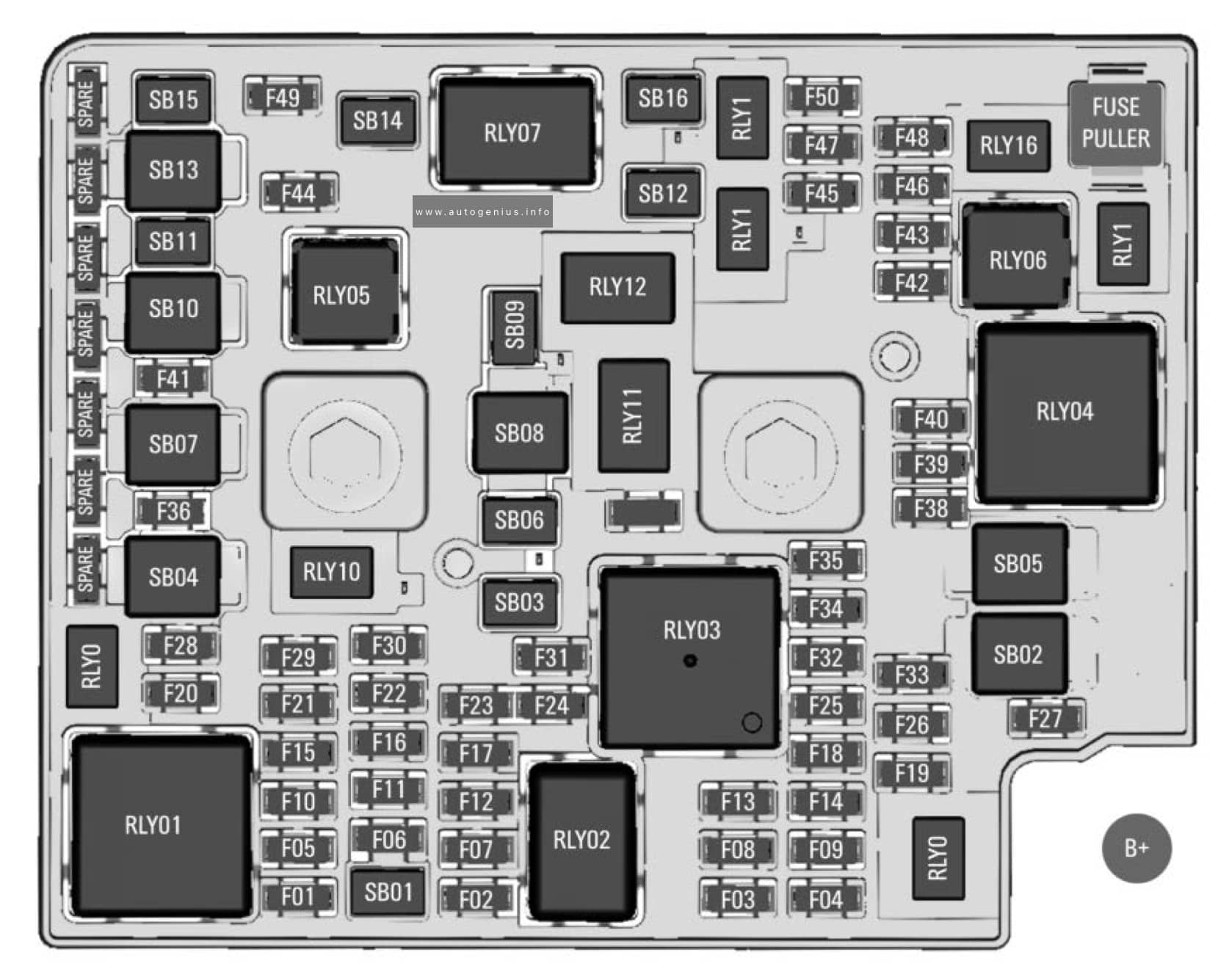
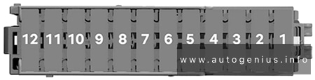
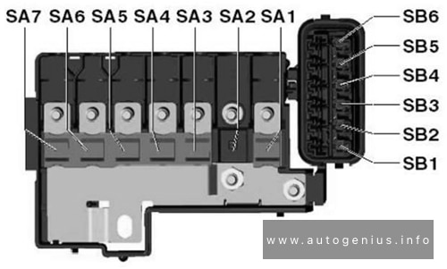
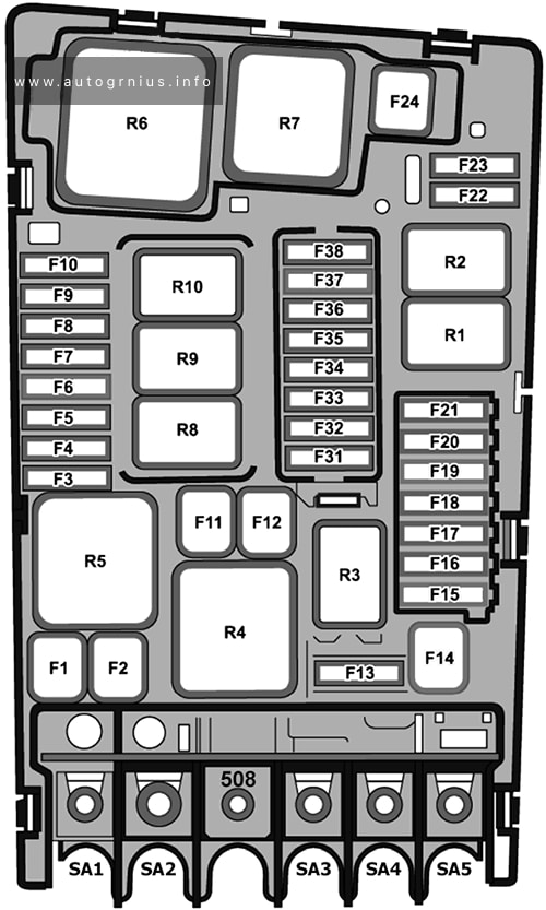
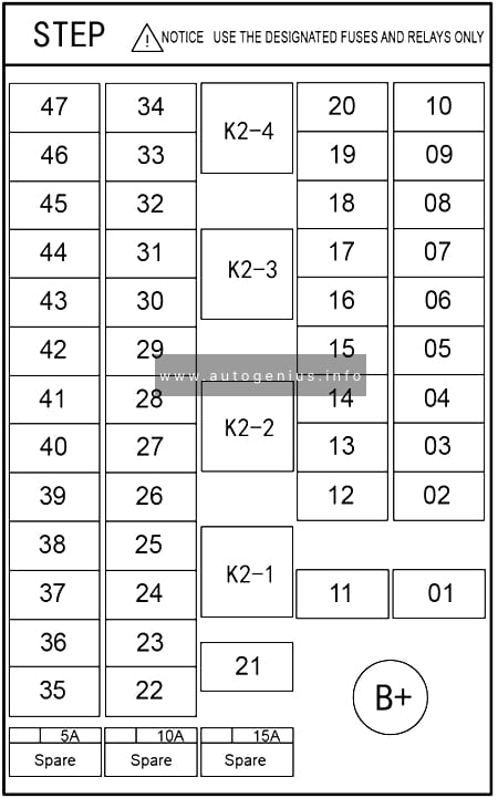
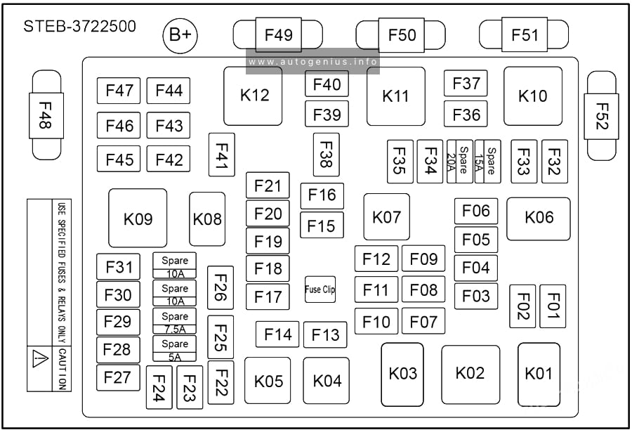
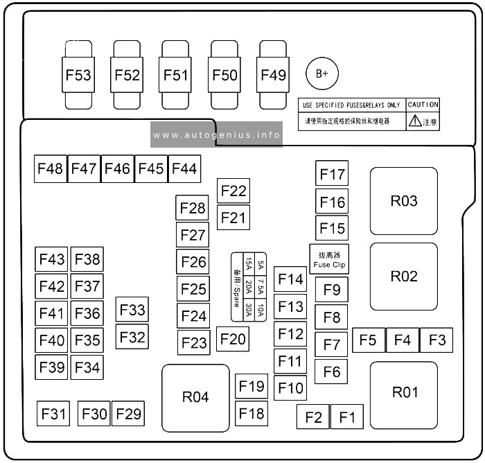
Fuse Box Diagram
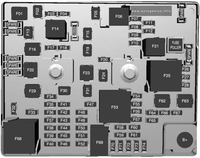
Assignment of the fuses in the engine compartment
| № | Usage |
|---|---|
| 1 | – |
| 2 | Power window rear |
| 3 | – |
| 4 | Rechargeable energy storage system 1 |
| 5 | – |
| 6 | – |
| 7 | Left high-beam headlight |
| 8 | Right high-beam headlight |
| 9 | Left low-beam headlight |
| 10 | Right low-beam headlight |
| 11 | Horn |
| 12 | – |
| 13 | Front wiper motor driver |
| 14 | Tailgate |
| 15 | Front wiper motor co-driver |
| 16 | Electronic brake control module supply electronics |
| 17 | Rear wiper |
| 18 | Tailgate |
| 19 | Seat module front |
| 20 | Washer |
| 21 | 2016-2017: HID light |
| 22 | Linear power module |
| 23 | Electronic brake control module supply motor |
| 24 | Seat module rear |
| 25 | Powertrain |
| 26 | Transmission range control module |
| 27 | Aero shutter |
| 28 | Auxiliary oil pump |
| 29 | E-booster motor source |
| 30 | Front power windows |
| 31 | In-panel bussed electrical centre |
| 32 | Rear window defogger |
| 33 | Heated exterior rear view mirror |
| 34 | Pedestrian friendly alert function |
| 35 | – |
| 36 | – |
| 37 | Current sensor |
| 38 | Rain sensor |
| 39 | – |
| 40 | E-booster (ECU) |
| 41 | Power line communication module |
| 42 | Automatic occupant sensing |
| 43 | Window switch |
| 44 | Rechargeable energy storage system |
| 45 | Vehicle integration control module |
| 46 | Integrated chassis control module |
| 47 | Headlight levelling device |
| 48 | Integrated chassis control module |
| 49 | Interior rear view mirror |
| 50 | – |
| 51 | E-booster |
| 52 | Rear camera |
| 53 | Run/Crank |
| 54 | A/C control module |
| 55 | Rechargeable energy storage system pump |
| 56 | – |
| 57 | Power electronics coolant pump |
| 58 | Engine control module |
| 59 | Electric steering column lock |
| 60 | HVAC electric heater |
| 61 | On-board charging module |
| 62 | Transmission range control module 1 |
| 63 | Electric cooling fan |
| 64 | Engine control module |
| 65 | Auxiliary heater pump |
| 66 | Powertrain relay |
| 67 | Drive unit controller |
| 68 | Rear window defogger |
| 69 | Second run/Crank relay |
| 70 | A/C control module |
| 71 | – |
| 72 | Transmission range control module |
| 73 | Single power inverter module |
| 74 | – |
WARNING: Terminal and harness assignments for individual connectors will vary depending on vehicle equipment level, model, and market.