Lincoln Aviator (U611; 2020 – 2024) – fuse and relay box diagram
Year of production: 2020, 2021, 2022, 2023, 2024
This article covers the second-generation Lincoln Aviator (U611), produced from 2019 onward. It includes fuse box diagrams for the 2020, 2021, 2022, 2023 and 2024 models, provides details on the locations of the fuse panels inside the vehicle, and explains the purpose and layout of each fuse and relay.
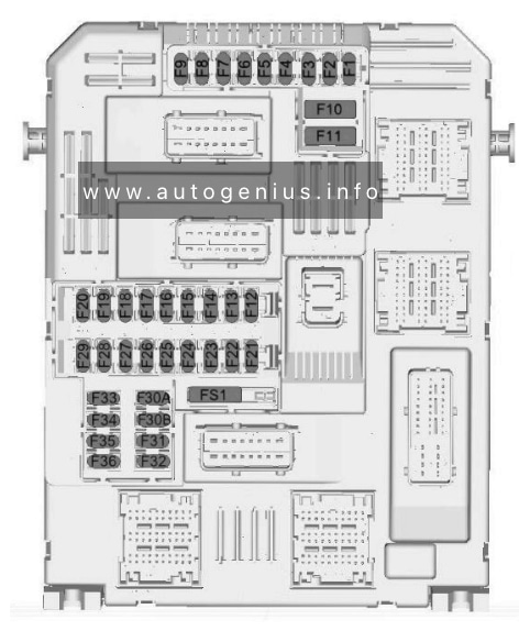
Passenger compartment fuse panel
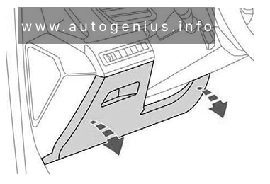
Fuse box location
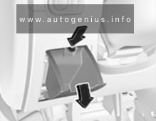
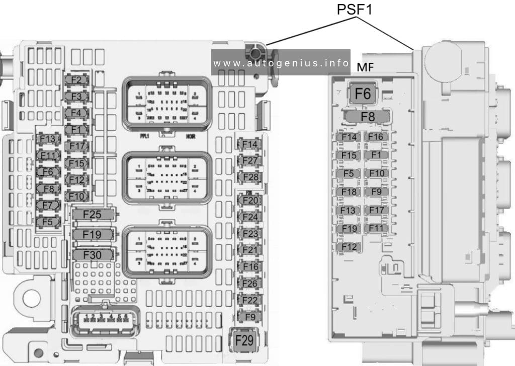
The fuse panel is located under the instrument panel to the left of the steering column.
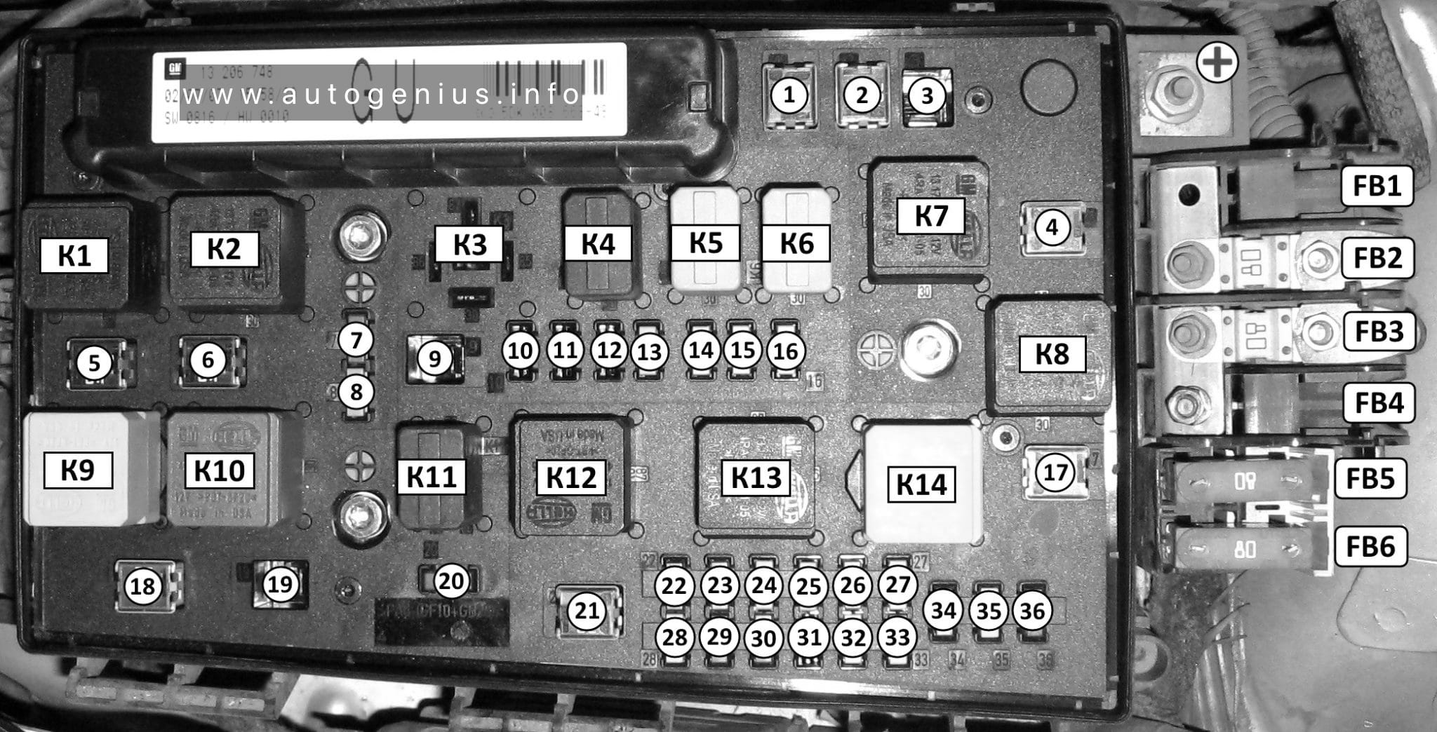
Fuse box diagram
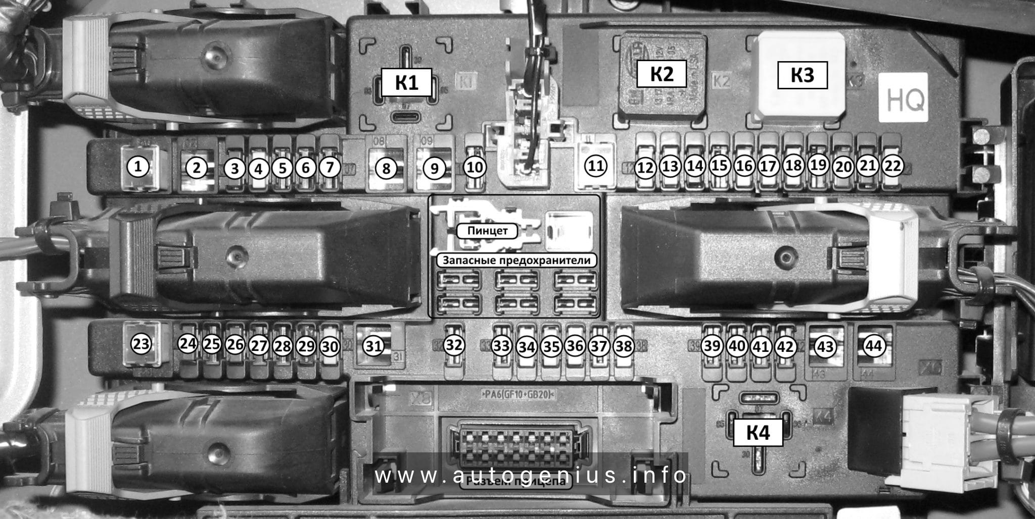
Assignment of the fuses in the passenger compartment
| Fuse | Ampere rating [A] | Description |
| 1 | — | Not used. |
| 2 | 10A | Moonroof. eCall. Telematics control unit module. Inverter. Driver door switch pack. |
| 3 | 7.5A | Memory seat switch. Wireless accessory charger module. Seat switches. |
| 4 | 20A | Not used (spare). |
| 5 | — | Not used. |
| 6 | 10A | Not used. |
| 7 | 10A | Smart data link connector power. |
| 8 | 5A | Telematics control unit module. Hands-free liftgate actuation module. Power liftgate module. |
| 9 | 5A | Combined sensor module. Keypad switch. Rear climate control. |
| 10 | — | Not used. |
| 11 | — | Not used. |
| 12 | 7.5A | Remote climate control module. Gear shift module. |
| 13 | 7.5A | Steering column control module. Switch interface module A. Smart datalink connector. Instrument cluster. |
| 14 | 15A | Not used (spare). |
| 15 | 15A | SYNC. Electronic finish panel. |
| 16 | — | Not used. |
| 17 | 7.5A | Headlamp control module. |
| 18 | 7.5A | Not used (spare). |
| 19 | 5A | Headlamp switch. Push button ignition switch. |
| 20 | 5A | Telematics control unit module. eCall. Bluetooth low energy module. |
| 21 | 5A | Not used. |
| 22 | 5A | Not used (spare). |
| 23 | 30A | Not used (spare). |
| 24 | 30A | Moonroof. |
| 25 | 20A | Not used (spare). |
| 26 | 30A | Not used (spare). |
| 27 | 30A | Not used (spare). |
| 28 | 30A | Not used (spare). |
| 29 | 15A | Head up display. |
| 30 | 5A | Trailer brake connector. |
| 31 | 10A | Terrain management switch. Transceiver module. |
| 32 | 20A | Audio control module. |
| 33 | — | Not used. |
| 34 | 30A | Run/start relay. |
| 35 | 5A | Not used (spare). |
| 36 | 15A | Park assist module. Electrochromic mirror. Suspension module. Image processing module A. |
| 37 | 20A | Not used (spare). |
| 38 | — | Not used. |
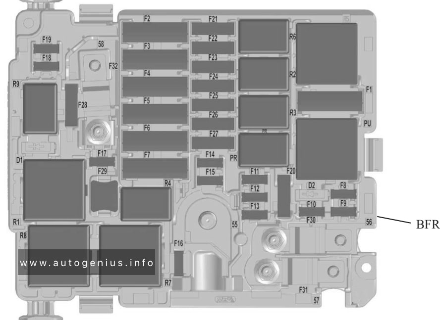
Engine compartment fuse box
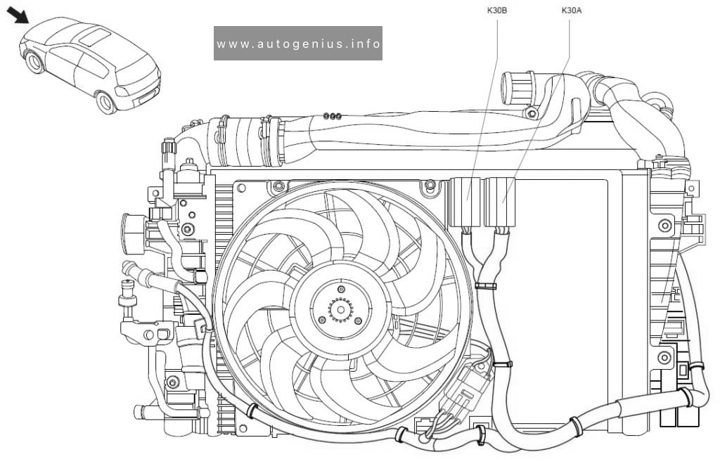
Fuse box location
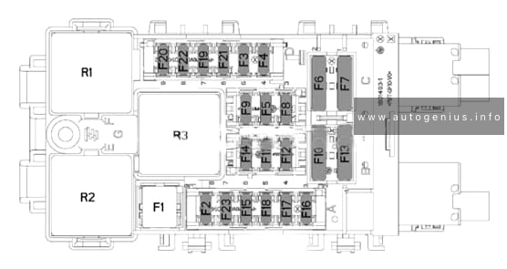
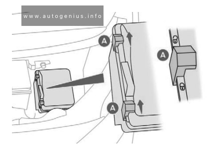
The engine compartment fuse box is under the driver’s side leaf screen.
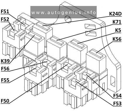
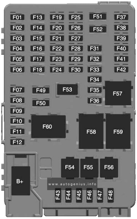
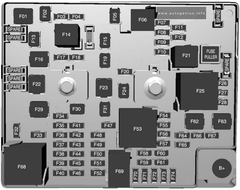
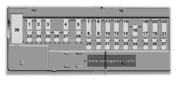
Fuse box diagram
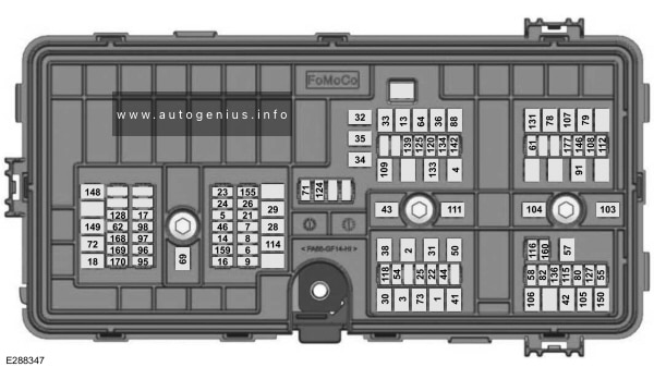
Assignment of the fuses in the engine compartment
| Fuse | Ampere rating [A] | Description |
| 1 | 40A | Body control module – battery power in feed 1. |
| 2 | 20A | Not used (spare). |
| 3 | 40A | Body control module – battery power in feed 2. |
| 4 | 30A | Fuel pump. |
| 5 | 5A | Powertrain control module keep alive power. |
| 6 | 20A | Powertrain control module power. |
| 7 | 20A | Canister vent solenoid. Evaporative leak control module. Exhaust gas heat recovery (2021-2023). Tank pressure control valve (2021-2023). Refueling valve (2021-2023). Vapor blocking valve. Universal exhaust gas oxygen 11. Universal exhaust gas oxygen 21. Catalyst monitor sensor 12. Catalyst monitor sensor 22. Canister purge valve. |
| 8 | 20A | Cooling fan relay coil. Battery interrupt box. Transmission oil pump. Auxiliary coolant pump. Fuel flap door (2021-2023). Engine coolant bypass valve. Active grille shutters. |
| 9 | 20A | Ignition coils. |
| 13 | 40A | Front blower motor relay. |
| 14 | 15A | Transmission oil pump. A/C compressor variable clutch. Engine mounts. Auxiliary pumps (2021-2023). |
| 16 | 15A | Windshield and rear window washer pump relay power. |
| 17 | 5A | 2021-2023: Charge status indicator. |
| 18 | 30A | Starter motor. |
| 21 | 10A | Headlamp leveling motors. Adaptive headlamps. |
| 22 | 10A | Electric power assisted steering module. |
| 23 | 10A | Anti-lock brake system module with integrated park brake. |
| 24 | 10A | Powertrain control module. Hybrid powertrain control module. |
| 25 | 10A | Air quality sensor. Particulate matter sensor. 360 camera with park aid. Rear view camera. Blind spot information system. Adaptive cruise control module. |
| 26 | 15A | Transmission control module. |
| 28 | 40A | Anti-lock brake system valves with integrated park brake. |
| 29 | 60A | Anti-lock brake system pump with integrated park brake. |
| 30 | 30A | Driver seat module. |
| 31 | 30A | Passenger seat module. |
| 32 | 20A | Not used (spare). |
| 33 | 20A | Rear cargo area power point. |
| 34 | 20A | Main console bin power point. |
| 35 | 20A | Not used (spare). |
| 36 | 40A | Power inverter. |
| 38 | 30A | Climate controlled seat module. |
| 41 | 30A | Power liftgate module. |
| 42 | 30A | Trailer brake control module. |
| 43 | 60A | Body control module. |
| 44 | 10A | Brake on and off switch. |
| 46 | 15A | 2021-2023: Battery charger control module. |
| 50 | 40A | Heated backlite. |
| 54 | 20A | Heated steering wheel. |
| 55 | 20A | Trailer tow park lamps. |
| 57 | 30A | Trailer tow battery charge. |
| 58 | 10A | Trailer tow backup lamps. |
| 61 | 15A | Multi-contour seat module. |
| 62 | 15A | Headlamp washer pump. |
| 64 | 40A | Four-wheel drive module. |
| 69 | 30A | Front window wiper motor. |
| 71 | 15A | Rear window wiper motor. |
| 72 | 20A | Air suspension module. |
| 73 | 30A | Driver door module. |
| 78 | — | Not used. |
| 79 | — | Not used. |
| 80 | 20A | Left-hand front electronic door. |
| 82 | 20A | Right-hand front electronic door. |
| 88 | 20A | Rear blower motor. |
| 91 | 20A | Trailer tow lighting module. |
| 95 | 15A | 2021-2023: Integrated spark control. |
| 96 | 15A | Not used (spare). |
| 97 | 10A | 2021-2023: Electric A/C. High voltage positive temperature coefficient heater. |
| 98 | 10A | 2021-2023: Traction battery coolant proportional valve. |
| 103 | 50A | Not used (spare). |
| 104 | 50A | Not used (spare). |
| 105 | 40A | 2020: Steering angle sensor module – adaptive front steering. |
| 106 | 40A | Not used (spare). |
| 107 | 40A | Not used (spare). |
| 108 | 20A | Not used (spare). |
| 109 | 30A | Passenger door module. |
| 111 | 30A | Body control module voltage quality monitor feed. |
| 112 | 20A | Left-hand rear electronic door. |
| 114 | 50A | Air suspension compressor. |
| 115 | 20A | Amplifier. |
| 116 | 5A | Not used (spare). |
| 118 | 30A | Second row heated seats. |
| 120 | 15A | Port fuel injectors. |
| 124 | 5A | Rain sensor. |
| 125 | 5A | USB smart charger 1. |
| 127 | 20A | Amplifier. |
| 128 | 15A | Illuminated badge. |
| 131 | 40A | Power folding seat module. |
| 133 | 15A | Left-hand heated wiper blade. Right-hand heated wiper blade. |
| 134 | 10A | Family entertainment system. |
| 136 | 20A | Right-hand rear electronic door. |
| 139 | 5A | USB smart charger 2. |
| 142 | 5A | Traffic cam. |
| 146 | 15A | 2021-2023: Battery electronic control module. |
| 148 | 30A | Left-hand headlamp module. |
| 149 | 30A | Right-hand headlamp module. |
| 150 | 40A | Not used (spare). |
| 155 | 25A | 2021-2023: Transmission control module. |
| 159 | 15A | 2021-2023: DC/DC converter. |
| 160 | 10A | Not used (spare). |
| 168 | 20A | 2021-2023: Low voltage service disconnect. |
| 169 | 10A | 2021-2023: Coolant pump. |
| 170 | 10A | 2021-2023: Traction battery coolant pump. Pedestrian sounder. |
| 177 | 10A | Center console blower. |
WARNING: Terminal and harness assignments for individual connectors will vary depending on vehicle equipment level, model, and market.