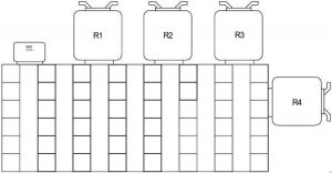
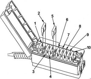
Kubota Power Krawler M8540 Narrow – fuse box diagram

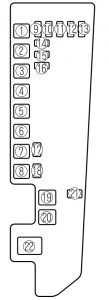
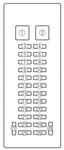
Kubota Power Krawler M8540 Narrow – fuse box diagram

Year of production:

Fuse box

Kubota Power Krawler M8540 Narrow - fuse box diagram
Kubota Power Krawler M8540 Narrow – fuse box diagram
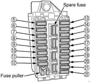
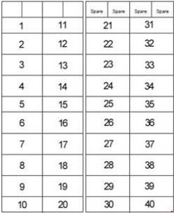
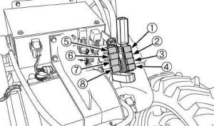
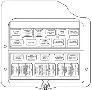
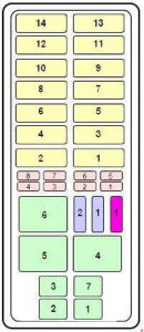
Number Ampere ratting [A] Protected circuit
1 20 Side Window Defogger
2 20 Rear Window Defogger
3 10 4WD / Bi-Speed Turn
4 10 45WD brake
5 15 Work Light (Rear)
6 15 Work Light (Front)
7 15 Cigarette Lighter
8 20 Air Conditioner (Fan Motor)
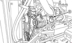
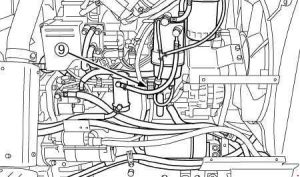
9 10 Air Conditioner (Compressor)
10 15 Work Light (Front, Side)
11 15 Auxiliary Power
12 5 Starter Relay
13 5 Radio
14 5 Air Conditioner (Control)
15 15 Wiper
16 5 Alternator, Engine, PTO, Heater
17 5 Meter Panel, OPC
18 10 Turn Signal, Stop Lamp
19 10 Meter, Radio (Back Up)
20 20 Head Light, Position Lamp
21 20 Flasher (Hazard)
22 20 Spare Fuse
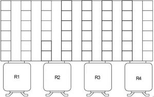
Kubota Power Krawler M8540 Narrow - fuse box diagram
Kubota Power Krawler M8540 Narrow – fuse box diagram
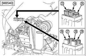
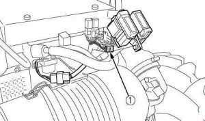
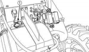
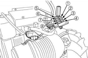
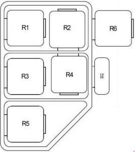
Number Ampere ratting [A] Protected circuit
23 50 Head Light, Hazard
24 50 Air Heater
25 100 Charge
26 30 Electrical Outlet
27 40 Air Conditioner
28 30 Work Light, Fuel Cut Solenoid
29 30 Key Switch

WARNING: Terminal and harness assignments for individual connectors will vary depending on vehicle equipment level, model, and market.

Mercedes-Benz B-Class W245 (2006 – 2011)  – fuse box diagram

Mercedes-Benz B-Class W245 (2006 – 2011)  – fuse box diagram

Year of production: 2006, 2007, 2008, 2009, 2010, 2011

Fuse box in the front-passenger footwell

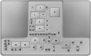
Mercedes-Benz B-Class W245 - fuse box diagram - in the front passenger-footwell
Mercedes-Benz B-Class W245 – fuse box diagram – in the front passenger-footwell
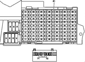
Number Fused function Ampere ratting [A]
1 2006-2008: Stop light switch 10
Light and vision package (2006-2008): Stop light switch
2009-2011: Stop light switch
5
2 Heated rear window 25
3 nstrument cluster
EIS [EZS] control unit
7,5
4 EIS [EZS] control unit
Electric steering lock control unit
15
5 Automatic air conditioning and Comfort automatic air conditioning:HEAT control and operating unit
Automatic air conditioning: AAC [KLA] control and operating unit
Comfort automatic air conditioning: Comfort AAC [KLA] control and operating unit
7,5
6 Left fanfare horn
Right fanfare horn
15
7 Fuel pump relay 25
8 Overhead control panel control unit 25
9 ESP and BAS control unit 40
10 Blower regulator/interior wiring harness connector 40
11 Valid for engine 266: Circuit 87 relay, engine 30
Valid for engine 640: Circuit 87 relay, engine 40
12 Steering column module
Multifunction steering wheel (2006-2008)
5
13 Left front door control unit 25
14 Right front door control unit 25
15 ESP and BAS control unit 25
16 Data link connector
Parktronic system (PTS) control unit (2006-2008)
10
17 Rotary light switch 5
18 Valid for transmission 711, 716: Backup lamp switch 7,5
19 Micromechanical turn rate sensor AY pickup 5
20 Restraint systems control unit 7,5
21 Starter relay 30
22 Instrument cluster 7,5
23 2006-2008: Washer nozzle heating 7,5
Valid for engine 640 as of 1.9.08: Fuel filter condensation sensor with heating element 20
24 Electric power steering (ES) control unit 7,5
25 Stop light switch
ESp and BAS control unit
7,5
26 Valid for transmission 722: Electronic selector lever module control unit 7,5
27 V10alid for transmission 722: CVT (continuously variable automatic transmission) control unit 7,5
28 Rotary light switch 5
29 SAM control unit 30
30 Circuit 87F relay 25
31 2006-2008:
Central gateway control unit (vehicles up to 30.11.05)
Rotary light switch
2009-2011:
Automatic light switch daylight sensor
Rain/light sensor
5
32 Valid for engine 266: ME-SFI [ME] control unit 7,5
33 Radio
Radio and navigation unit
COMAND operating, display and control unit (Japan)
15
34 Left rear door control unit 25
35 Right rear door control unit 25
36 2006-2008:
Cell phone separation point
Trailer control unit
7,5
2009-2011:
Trailer control unit
PTS control unit
10
37 Restraint systems control unit
Front passenger seat occupied recognition sensor
Front passenger seat occupied and child seat recognition sensor
7,5
38 Front cigar lighter with ashtray illumination 25
39 Wiper motor 25
40 Louvered sunroof: Overhead control panel control unit 7,5
Lamella roof: Overhead control panel control unit 25
41 Liftgate wiper motor 15
42 Glove compartment illumination with switch
Left and right vanity mirrors illumination
Footwell illumination switch (driving school package)
Pedal operation monitor switch (driving school package)
VICS+ETC voltage supply separation point (Japan)
7,5
43 Valid for engine 266:
Terminal 87M1 e connector sleeve
Bivalent natural gas drive (2009-2011):
Terminal 87M1e connector sleeve
15
Valid for engine 640:
Terminal 87M1e connector sleeve
7,5
44 Valid for engine 266:
Terminal 87M2e connector sleeve
15
Valid for engine 640:
Terminal 87M2e connector sleeve
20
45 Valid for engine 640:
CDI control unit
25
46 2006-2008:
Telephone control unit, (Japan)
E-net compensator
Universal Portable CTeL Interface (UPCI [UHI]) control unit
7,5
2009-2011: Bass module speaker (Japan) 25
2009-2011: Amplifier for sound system 40
47 Telephone control unit, (Japan)
Universal Portable CTEL Interface (UPCI [UHI]) control unit
Cell phone separation point
Voice control system (VCS [SBS]) control unit
7,5
48 ATA [EDW]/tow-away protection/interior protection control unit
Alarm signal horn with additional battery
7,5
49 Upper control panel control unit
Left front seat heated cushion (2006-2008)
Left front backrest heated cushion (2006-2008)
Right front seat cushion heater element (2006-2008)
Right front backrest seat cushion heater element (2006-2008)
25
50 2006-2008:
CD changer
VICS+ETC voltage supply separation point (Japan)
2009-2011:
Media interface control unit
Digital TV tuner
Digital Audio Broadcasting control unit
7,5
Valid for government vehicles (2009-2011):
Roof light bar
Circuit 30 connector sleeve
30
51 Canada (2009-2011): Weight Sensing System (WSS) control unit
Valid for government vehicles (2009-2011): Special signal system control panel
10
52 VICS+ETC voltage supply separation point (Japan) (vehicles up to 31.5.0 5
Spare (vehicles as of 1.6.06) 7,5
Emergency call system control unit (USA) (vehicles up to 31.5.06) 7,5
53 Rear cigar lighter with ashtray illumination
Interior socket
30
54 Amplifier for sound system
Bass module speaker
25
Valid for government vehicles (2009-2011): 2-pin 12V socket 15
55 Left front lamp unit (Bi-xenon)
Right front lamp unit (Bi-xenon)
7,5
Left front lamp unit (Hi-xenon) 10
56 Spare 10
Right front lamp unit (Hi-xenon) 10
57 2009-2011: Trailer hitch socket (13-pin) 15
2006-2008: Audio gateway control unit (Japan) 25
2006-2008:
SDAR control unit
Emergency call system control unit (USA)
7,5
58 Trailer control unit 25
59 Trailer control unit (vehicles up to 31.5.05)
Trailer hitch socket (13-pin) (vehicles as of 1.6.05)
20
60 Driver seat connector block 20
61 Front passenger seat connector block 20
62 Circuit 15 relay (2) (SA: xenon, cell phone) 25
63 Spare (vehicles up to 31.5.05)
Valid for government vehicles (2009-2011): Roof light bar 25
Emergency call system control unit (USA) (vehicles as of 1.6.05)
SDAR control unit (vehicles as of 1.6.05)
7,5
64 Valid for engine 266: Air pump relay 40
Valid for engine 640:
Engine wiring harness/engine compartment connector (2006-2008)
Glow time output stage (2009-2011)
80
65 Electric power steering (ES) control unit 80
66 SAM control unit 60
67 Circuit 15R relay (2) (SE) 50
68 Valid for engine 266.920 and engine 266.940 with transmission 722:
AAC with integrated control additional fan motor
50
Valid for engine 640.940, 640.941, 266.960, 266.980 and for engine 266.920, 266.940 with (Trailer hitch):
AAC with integrated control additional fan motor
60
69 Circuit 15R relay (1) 50
70 Circuit 15 relay (1) 60
71 Valid for engine 640: PTC heater booster 150
72 2006-2008: Circuit 30 connector sleeve
2009-2011:
Special vehicle multifunction control unit (SVMCU [MSS]) (Taxi)
Valid for government vehicles:
Fuse 7
Fuse 10
60
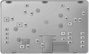
Mercedes-Benz B-Class W245 - fuse box diagram - in the front passenger-footwell
Mercedes-Benz B-Class W245 – fuse box diagram – in the front passenger-footwell
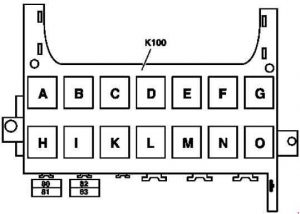
Number Fuse function Ampere ratting [A]
80 Special vehicle multifunction control unit 30
81 Special vehicle multifunction control unit 30
82 Special vehicle multifunction control unit 30
83 Special vehicle multifunction control unit 30
Relay
A Circuit 15R relay (2) (SA)
B Circuit 15R relay (1)
C Fanfare horn relay
D Heated rear window relay
E Wiper stage 1/2 relay
F Wiper ON/OFF relay
G Circuit 15 relay (1)
H Backup relay
I Valid for engine 266: Air pump relay
K Fuel pump relay
L Engine circuit 87 relay
M Starter relay
N Circuit 87F relay
O Circuit 15 relay (2) (SA: xenon, cell phone)

WARNING: Terminal and harness assignments for individual connectors will vary depending on vehicle equipment level, model, and market.

Kubota M100GX, M110GX, M126GX, M135GX – fuse box diagram

Kubota M100GX, M110GX, M126GX, M135GX – fuse box diagram

Year of production:

Fuse box diagram

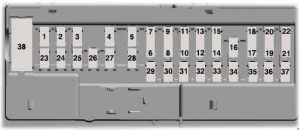
Kubota M100GX, M110GX, M126GX, M135GX - fuse box diagram
Kubota M100GX, M110GX, M126GX, M135GX – fuse box diagram
Number Ampere ratting [A] Description
1
2 10 ECU (Suspension)
3 5 ECU (Switch)
4 20 Defogger
5
6 10 Brake lamp
7 5 Radio
8 5 Air conditioner (Fan control)
9 15 Wiper
10 5 Starter relay
11
12 5 Switch (Transmission control)
13 5 Switch (Hitch control)
14 10 ECU (Main)
15 5 Main meter
16 5 4WD, Bi-speed, Differential lock
17 5 Engine control, PTO valve
18 10 Turn signal
19 15 Loader power aux socket
20 5 LCD monitor
21 15 Work light (Cabin side)
22 15 Work light (Front upper)
23
24
25 10 Option lamp
26 15 Work light (Rear)
27 10 Work light (Bonnet)
28 15 Seat compressor
29 15 Cigarette socket
30 15 Work light (Option)
31
32 15 Head lamp
33 30 Air conditioner fan motor
34 10 Air conditioner compressor
35 15 Tail lamp
36 15 Hazard
37 10 Dome light, Radio
38 5 Horn
39 5 Glow relay
40 5 Back up (ECU, Meter)

M100GX, M110GX

Kubota M100GX, M110GX - fuse box diagram
Kubota M100GX, M110GX – fuse box diagram

M126GX, M135GX

Kubota M126GX, M135GX - fuse box diagram
Kubota M126GX, M135GX – fuse box diagram
Number Ampere ratting [A] Description
1 20 CRS POWER

M100GX, M110GX

Kubota M100GX, M110GX - fuse box diagram
Kubota M100GX, M110GX – fuse box diagram

M126GX, M135GX

Kubota M126GX, M135GX - fuse box diagram
Kubota M126GX, M135GX – fuse box diagram
Number Ampere ratting [A] Description
1 40 Defogger
2 30 Electrical outlet
3 40 Work light (Rear)
4 120 M100GX, M110GX: Engine preheat
40 M126GX, M135GX:
Work light (Hood)
Head lamp
5 40 M100GX, M110GX:
Work light (Hood)
Head lamp
60 M126GX, M135GX: Engine preheat
6 40 Compressor
7 30 Hazard
8 30 Main key switch

M100GX, M110GX

Kubota M100GX, M110GX - fuse box diagram
Kubota M100GX, M110GX – fuse box diagram

M126GX, M135GX

Kubota M126GX, M135GX - fuse box diagram
Kubota M126GX, M135GX – fuse box diagram
Number Ampere ratting [A] Description
9 140 Alternator

WARNING: Terminal and harness assignments for individual connectors will vary depending on vehicle equipment level, model, and market.

BMW 3 Series E36 and E35/5 (1990 – 2000) – fuse box diagram

BMW 3 Series E36 and E35/5 (1990 – 2000) – fuse box diagram

Years: 1990, 1991, 1992, 1993 ,1994, 1995,

Front power distribution box

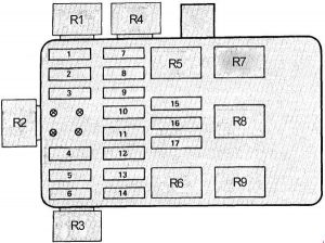
BMW 3 Series E36 and E35/5 - fuse box diagram - front box distribution box
BMW 3 Series E36 and E35/5 – fuse box diagram – front box distribution box
Fuse Ampere rating [A] Description
1 30 Power tilt/slide sunroof (SHD)
2 15 as of 9/93: Trailer coupling
5 as of 9/96: Engine control system
3 30 Rear wipe/wash interval control unit (Touring, Compact)
Headlight washer system (SRA)
Radio/HiFi (9/94 to 8/95)
4 15 Unloader relay terminal 15 (Heated seats)
5 30 Passenger’s seat adjustment switch
6 20 Rear defogger relay
30 Rear defogger relay
7 5 Electronic gear indicator
Central locking switch
Driver’s door lock switch
Central locking (ZV) drive driver’s door
Central locking module (ZVM)
Central locking (ZV) drive passenger’s door
Passenger’s door lock switch
Control unit, remote control
Rear lid lock relay
Central locking drive rear lid (Touring)
Rear lid microswitch (mechanical convertible soft top)
Convertible soft top flap lock
Convertible soft top module
Anti-theft control module (Alpine)
8 15 Horn relay
Anti-theft control module (Alpine)
9 20 Radio
Hifi amplifier
Subwoofer
CD changer (to 8/93)
Unloader relay terminal R (to 8/92)
10 30 Antilock brake system (ABS)
Automatic stability control (ASC)
11 7,5 without CCM: Left low beam light
with CCM: Check control module
12 7,5 without CCM: Right low beam light
with CCM: Check control module
13 5 Comfort relay (two–door model)
14 30 Driver’s side power window module (to 8/93)
Passenger’s side power window module (to 8/93)
ZKE control unit (ZKE IV; as of 9/93)
15 15 Left fog light
Right fog light
Instrument cluster
7,5 Left fog light
Right fog light
Instrument cluster
16 5 A/C compressor relay
Auxiliary fan stage 1 relay (normal speed relay)
Auxiliary fan stage 2 relay (high speed relay)
17 10 without CCM: Fog light switch (Rear fog light switch)
7,5 with CCM: Fog light switch (Rear fog light switch)
18 15 Fuel pump
19 15 to 8/92: Park heating/ventilation relay box
30 as of 8/93: Relay module
20 30 to 8/92: Blower switch
as of 9/92:
   without park ventilation: Heating blower relay
   with park ventilation:
Heating blower relay
Independent ventilation relay
21 5 Antilock brake system (ABS)
Automatic stability control (ASC)
22 5 Light switch
Daytime running lights coding diode
23 5 Combination switch (turn indicator/low beam selector)
Instrument cluster
Thermal switch (LA Japan)
ABS control unit
Rear defogger relay
Multi–function clock / On–board display / On–board computer
Unloader relay terminal 15
with IHKA: Automatic climate control unit
with heating control:
Water valves
Temperature regulator
24 10 Thermal switch, heated jets
Rollover sensor
Mirror control unit
Parking aid control unit
25 5 Light switch
Day light relay module (as of 9/97)
High beam relay (9/94 to 8/97)
Low beam relay (9/92 to 8/94)
Left park light relay (9/93 to 8/94)
Right park light/license plate light relay (9/93 to 8/94)
26 15 to 8/92:
Program switch
Auxiliary connector (US)
Automatic transmission range switch
Diagnostic connector
Reversing light switch (without EGS)
10 as of 9/92:
Automatic transmission range switch
Program switch
Fuel heating (diesel)
Alternator cut–out relay (diesel)
Diagnostic connector
Oil level switch, thermal
Oxygen sensor and air pump relays
Reversing light switch
SMG control unit
Hydraulic pump relay
Hydraulic unit
Starter immobilization relay
Throttle flap heater
27 5 Instrument cluster
28 5 with EGS: Automatic transmission range switch
with SMG:
SMG control unit
Electronic gear indicator
Gear indicator, centre console
29 7,5 Left high beam
30 7,5 Right high beam
31 5 Instrument cluster
On–board display / Multi–function clock
On–board computer
Analogue clock
Chime module
Electronic immobiliser control unit (EWS II; as of 9/94)
Antitheft (DWA) LED
With IHKA:
Water valves
Automatic climate control unit
With IHKR:
IHKR control panel
Integrated climate regulation control module
32 30 Front cigar lighter
Reading lights relay
33 10 Ignition switch (as of 9/93)
Charge socket
Light switch
CD changer (as of 9/93)
Cellular telephone
Door lock heating relay
Luggage compartment light
Rear compartment interior light, centre (Touring)
Right trunk light assembly (Compact)
Interior light, right rear (with reading light)
Interior light, left rear (with reading light)
Interior/reading lamp, front (with ZKE)
ZKE control unit (as of 9/93)
Front left footwell light (Front right footwell light)
Left parking light relay
Driver’s side power window module (to 8/93)
34 15 Hazard flasher relay
Crash alarm sensor (with crash alarm sensor)
35 25 with ZVM: Central locking module (ZVM)
with ZKE: ZKE control unit
36 30 Wipe–wash module (Low II) / Wipe/wash module
37 10 Light switch
Right parking light/licence plate light relay
38 30 Antilock brake system (ABS)
Automatic stability control (ASC)
39 7,5 A/C compressor relay
40 30 Driver’s seat adjustment switch
Driver’s lumbar support switch
41 30 Auxiliary fan stage 1 relay (low; only diesel)
Auxiliary fan stage 2 relay (high)
42 7,5 Electronic seat control
Driver’s side impact sensor
Passenger’s side impact sensor
Rollover sensor
Airbag diagnostic module
Driver’s seat belt buckle switch
43 5 Interior light, right rear
Interior light, left rear
Top Hifi switch
Central locking module (ZVM)
ZKE control unit
Spatial sound relay
Passenger’s make–up mirror light
Driver’s make–up mirror light
Interior/reading lamp, front
Convertible soft top module
Control unit, remote control
Cellular telephone
Reading lights relay
Anti-theft control module (Alpine)
44 15 Wipe–wash module (Low II)
Wipe/wash module
Rear wipe/wash interval control unit (Touring, Compact)
Windscreen wiper switch (Touring, Compact)
Radio
Glovebox light/switch
Twin relay module (up to 8/95)
Unloader relay terminal R (up to 8/92)
45 7,5 Check control module
Transmit/receive module (EWS II; as of 9/95)
Starter immobilization switch (as of 9/96)
On–board computer / Multi–function clock / On–board display
Wiper relay (up to 8/95)
Wiper motor relay (up to 8/95)
46 15 Clutch switch
Instrument cluster
Brake light switch
Cruise control module
Cruise control switch
Data link connector (as of 9/95)
Board computer (BC-low)
Relay
R1 Fuel pump relay
Oxygen sensor and air pump relays (M3)
Secondary air pump relay
Engine control module relay
Alternator cut–out relay (diesel)
R2 Engine control module relay
Fuel pump relay
R3 Oxygen sensor relay
EKP and start detector relay
Wiper motor relay
Engine control module relay
Secondary air pump relay
Delivery pump relay (diesel)
R4 Horn relay
R5 Fog light relay
R6 High beam relay (to 8/93)
Low beam relay (as of 9/93)
R7 Low beam relay (to 8/93)
High beam relay (as of 9/93)
Secondary air pump relay
R8 Hazard flasher relay
R9 Blower relay
R10 Rear defogger relay
R11 ABS relay
R12 ABS pump motor relay
ABS pump motor relay, timed
R13 Auxiliary fan stage 2 relay (high speed)
R14 A/C compressor relay
R15 Auxiliary fan stage 1 relay (low speed)

Relay carrier under LH side of dash

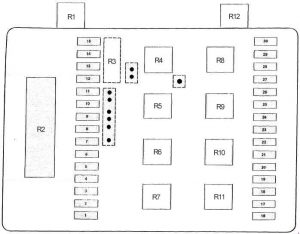
BMW 3 Series E36 and E35/5 - fuse box diagram - relay carrier under LH side of dash
BMW 3 Series E36 and E35/5 – fuse box diagram – relay carrier under LH side of dash
Fuse Ampere rating [A] Description
48 40 Auxiliary fan stage 2 relay (high speed)
50 5 Exhaust gas flap valve
Carbon canister valve
Relay
R1 Independent ventilation relay
R2 Twin relay (up to 8/95)
R3 Crash alarm sensor
R4 Headlight/foglight cleaning module (SRA) (up to 8/95)
High beam relay
Day running ligth relay
R5 Comfort relay
Folding sunroof comfort relay
R6 Unloader relay terminal R (up to 8/92)

Connector strip under LH side of dash

BMW 3 Series E36 and E35/5 - fuse box diagram - connector strip under LH side of dash
BMW 3 Series E36 and E35/5 – fuse box diagram – connector strip under LH side of dash
Fuse Ampere rating [A] Description
47 158 Horn relay (Alpine)
On-board computer
Anti-theft control module (Alpine)
Relay
R1 Unloader relay terminal 15
Horn relay (Compact)
R2 Rear lights relay
Wiper relay (up to 8/95)
R3 Wiper motor relay (up to 8/95)
R4 Hinged window relay
Starter relay (up to 8/94)
Starter immobilization relay (9/93 to 9/94)

Connector strip under RH side of dash

BMW 3 Series E36 and E35/5 - fuse box diagram - connector strip under RH side of dash
BMW 3 Series E36 and E35/5 – fuse box diagram – connector strip under RH side of dash
Number Realy
R1 Right parking light/licence plate light relay
R2 Left parking light relay
Thermal switch (LA Japan)
R3 Door lock heating relay
R4 Rear window blower relayWARNING: Terminal and harness assignments for individual connectors will vary depending on vehicle equipment level, model, and market.

WARNING: Terminal and harness assignments for individual connectors will vary depending on vehicle equipment level, model, and market.

BMW 7 E23 (1977 – 1987) – fuse box diagram

BMW 7 E23 (1977 – 1987) – fuse box diagram

Years: 1977, 1978, 1979, 1980, 1981, 1982, 1983, 1984, 1985, 1986, 1987

Fuse Box (up to 1982)

BMW 7 E23 - fuse box diagram
BMW 7 E23 – fuse box diagram
Fuse Ampere rating [A] Description
1 15 Fuel Delivery/Evaporative Control
Idle Speed Control
2 8 Headlights (RH Low Beam)
3 8 Headlights (LH Low Beam)
4 25 Cigar Lighters
5 8 Active Check Control
Auto-Charging Flashlight
Central Locking
Gauges
Glove Box Light
Heated Door Lock
Ignition Key Warning/Seatbelt Warning
Interior Lights
Lights: Turn/Hazard Warning
On-Board Computer
Radio/Power Antenna
Trunk Light
6 8 Active Check Control
Backup Lights/Transmission Range Lights
Brake Lining Warning
Cruise Control
Dash Lights
Gauges
Idle Speed Control
Interior Lights
Power Mirrors
Power Windows
Seatbelt Warning
Speedometer
Warning Indicators
7 8 Headlights (LH, RH High Beams)
8 8 Headlights (LH, RH High Beams)
9 8 Active Check Control
Dash Lights
Lights: Front Park/Tail/Underhood
Lights: Rear Marker/License
10 8 Active Check Control
Lights: Front Park/Tail
11 16 Active Check Control
Horns
Lights: Turn/Hazard Warning
Wiper/Washer
12 8 Active Check Control
Radio/Power Antenna
Stoplights/Cruise Control
Warning Indicators
13 25 Rear Defogger/Sunroof
14 25 Automatic Heater-Air Conditioner
Auxiliary Fan
Vacuum Pump
15 8 Fog Lights (RH)
16 8 Fog Lights (LH)
17 25 Auxiliary Fan
Relay
R1 Fuel Pump Relay
R2 Auxiliary Fan Relay (Speed 1)
R3 Low Beam Check Relay
R4 Purge Valve Relay
R5 High Beam Relay
R6 Horn Relay
R7 Low Beam Relay
R8 Fog Light Relay
R9 Unloader Relay


Ampere ratting [A] Protected circuits
Auxiliary Fan Fuses(2) 25 Auxiliary Fan


Under Dash, Left Of Console

Ampere ratting [A] Protected circuits
Power Window Circuit Breaker 25 Power Windows


Ampere ratting [A] Protected circuits
In-Line Radio 25 Radio

Fuse Box (from 1982)

BMW 7 E23 - fuse box diagram
BMW 7 E23 – fuse box diagram
Fuse Ampere rating [A] Description
1 15 Headlights (Left High Beam, Right Low Beam)
2 15 Headlights (Right High Beam, Left Low Beam)
3 15 Auxiliary Fan 91° C (196° F)
4 15 Lights: Turn/Hazard Warning
5 30 Wiper/Washer, Windshield Washer Jet Heaters
6 7,5 Active Check Control, Stop Lights/Cruise Control/Map Light
7 15 Horn
8
9 15 Back Up Lights, Fuel Control (Engine Electrical Equipment)
10 7,5 Active Check Control, Brake Lining Warning, On-Board Computer, Seatbelt Warning, Service Interval Indicator, Speedometer/Gauges/Warning Indicators
11 15 Fuel Delivery (Main and Auxiliary Fuel Pump)
12 7,5 Active Check Control, On-Board Computer, Radio (Radio In-Line Fuse), Warning Indicators
13 7,5 Headlights (Left Low Beam)
14 7,5 Headlights (Right Low Beam)
15
16 30 Auxiliary Fan, Vacuum Pump, Heater/Air Conditioning
17 15 Heater/Air Conditioning, Interior Lights, Power Mirrors, Power Windows, Seatbelt Warning, Stop Lights/Cruise Control, Windshield Washer Jet Heaters
18 30 Auxiliary fan 99° C (210° F)
19 30 Sunroof, Heated Seats
20 30 Hear Defogger
21 7,5 Active Check Control, Auto-Charging Flashlight, Gauges, Glove Box Light, interior Lights, On-Board Computer, Radio, Service Interval Indicator, Trunk Lights, Seat Belt Buzzer, Memory, Clock
22 7,5 Active Check Control, Lights: Front Park/Tail
23 7,5 Active Check Control, Rear Defogger, Lights: Front Park/Tail Underhood, Lights: Visor/Dash, Lights: Rear Marker, Lights: Turn/Hazard Warning, Engine Compartment Light, License Plate Lights
24 15 Lights: Turn/Hazard Warning, Open Door Buzzer
25
26 30 Power Seats, Power Windows
27 30 Central Locking, Heated Door Lock, On-Board Computer, Burglar Alarm
28 30 Cigar Lighter, Power Antenna (Radio In-Line Fuse)
29 7,5 Fog Lights (Left Fog Light)
30 7,5 Fog Lights (Right Fog Light)
32 30 Accessory Fuse (Not Used)
33 30 Accessory Fuse (Not Used)
Relay
R1 Fuel Pump Relay
R2 Wiper Control Unit
R3 Low Beam Check Relay
R4 Low Beam Relay
R5 High Beam Relay
R6 Horn Relay
R7 Auxiliary Fan Relay (Speed 1)
R8 Fog Light Relay
R9 Unloader Relay (Rear Window Defogger, Power Sliding Roof, Heated Seat)
R10 Auxiliary Fan Relay (Speed 2)
R11 Unloader Relay (Heater Blower)
R12 Oxygen Sensor Heater Relay


Ampere ratting [A] Protected circuits
Power Window Circuit Breaker 25 Power Windows

WARNING: Terminal and harness assignments for individual connectors will vary depending on vehicle equipment level, model, and market.

Ford Ranger T6 (2011 – 2018) – fuse box diagram

Ford Ranger T6 (2011 – 2018) – fuse box diagram

Year of production: 2011, 2012, 2013, 2014, 2015, 2016, 2017, 2018

Engine Compartment Fuse Box (Type 1)

Ford Ranger - fuse box diagram - engine compartment fuse box (type 1)
Ford Ranger – fuse box diagram – engine compartment fuse box (type 1)
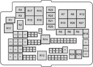
Fuse Ampere rating [A] Description
1 60 Passenger compartment fuse box supply (Battery)
2 60 Passenger compartment fuse box supply (Battery)
3 50 Petrol: Engine cooling fan
60 Diesel: Glow plug control module
4 40 Anti-lock brake system module
5 30 Power windows (front and rear)
6 25 2011-2014: Four wheel drive (4WD) motor ground
7
8
9 20 Power seats
10 20 2015-2018: Auxiliary power socket instrument panel, console top
25 2011-2014: Electric windows (front)
11 30 Blower motor
12 25 Four wheel drive (4WD) motor power
13 20 Starter solenoid
14 20 Heated rear window
15 10 Petrol: Flex-fuel pump
20 Diesel (2013-2016): Vaporizer glow plug
15 Diesel (2011-2012 and 2017-2018): Vaporizer glow plug
16 10 Air conditioning clutch
17 25 Power windows (front)
18 25 Windscreen wiper motor
19 25 2011-2014: Windscreen wiper motor ground
20 20 Cigar lighter
21 15 Horn
22 15 2011-2016: Fuel injectors, flex-fuel valve
10 2017-2018: Fuel injectors, flex-fuel valve.
23 10 Differential lock solenoid
24 20 2011-2014: Auxillary power socket (front console)
25 15 Ignition coils, temperature and mass air flow sensor, glow plug module, vacuum control valve (VCV), electronic vacuum regulator valve (EVRV)
26 7,5 Electronic control module (ECM)
27 10 Transmission control module (TCM)
28 10 Heated exhaust gas oxygen, universal heated exhaust gas oxygen-sensor, relay coils
29 15 Electronic control module (ECM)
30 5 2015-2018: Battery monitoring sensor
15 2011-2014: Battery monitoring sensor
31 20 Auxiliary power socket (rear console)
32 5 Air conditioning pressure switch
33 10 Transmission control module (TCM)
34 5 2014-2018: Crew chief module
2011-2013: PTC heater (where fitted)
35 20 Passenger compartment fuse box supply (Ignition)
36 5 Anti-lock brake system module
37 10 Headlamp leveling
38 20 2011-2014: Heated seat
39 10 Power mirrors
40 10 Vapourizer pump
41 10 Heated mirrors
42 10 Alarm horn
43 30 2011-2014: Heated windscreen (right)
44 30 2011-2014: Heated windscreen (left)
45 25 Anti-lock brake system module
46 20 2011-2014: Auxillary power socket (bedliner (floor console))
20 2015-2018: Battery isolator
47 40 Trailer tow module
48
49
50 5 Ignition relay, relay coils
51 20 2011-2018: Trailer Tow (12/13pin Batt feed / Permanent Live)
30 2011-2014: Electric windows (rear)
Relay
R1 Key interlock
R2 Wiper on or off
R3 Horn
R4 Air conditioning clutch
R5 Differential lock
R6 Wiper Hi or Lo
R7 Engine cooling fan low
R8 Engine cooling fan high
R9 Flex-fuel pump, vaporizer glow plug
R10 Heated rear window
R11 2011-2014: Heated windscreen
R12
R13 Electronic control module (ECM) power hold
R14 Ignition
R15 4WD motor 2 (clockwise)
R16 4WD motor 1 (counter clockwise)
R17 4WD motor
R18 Security horn
R19 Starter
R20
R21
R22
R23
R24
R25
R26 Blower motor
R27 Power seat

Passenger Compartment Fuse Box – Type 1

Ford Ranger - fuse box diagram - passenger compartment fuse box (type 1)
Ford Ranger – fuse box diagram – passenger compartment fuse box (type 1)
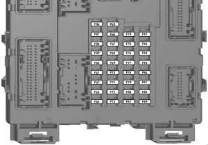
Number Ampere rating [A] Description
56 20 Fuel pump
57
58
59 5 Passive anti-theft system (PATS)
60 10 Interior lamp, driver’s door switch pack, mood lights, puddle lights, automatic shifter, footwell lamp
61
62 5 Rain sensor module
63 5 Tachograph
64
65
66 20 Driver’s door unlock, central double locking
67 5 Stop lamp switch
68
69 5 Instrument cluster, integrated control module (ICP), tracking and blocking module
70 20 Central locking
71 5 Air conditioning
72 7,5 Alarm horn
73 5 On-board diagnostics II
74 20 Main beam
75 15 Front fog lamps
76 10 Reversing lamp, rear view mirror
77 20 Washer pump
78 5 Ignition switch
79 15 Radio, Audio signal DIN, FSAO audio, multi-function display
80 20 Multi-function display, Hi audio, bluetooth audio (2015-2018), brake valve closing (BVC) module (2011-2014)
81 5 Interior motion sensor
82 20 Washer pump ground
83 20 Central locking ground
84 20 Driver’s door unlock, central double locking ground
85 7,5 Instrument cluster, parking aid module, rearview camera, manual air conditioning, rear view mirror, tracking and blocking module
86 10 Restraint system, passenger air-bag deactivation indicator
87 7,5 Tachograph
88
89

Auxiliary Fuse Box

Ford Ranger - fuse box diagram - auxiliary fuse box
Ford Ranger – fuse box diagram – auxiliary fuse box
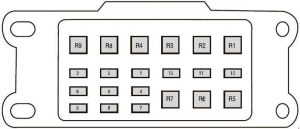
Fuse/Relay location Ampere rating [A] Description
1 25 Driving Light
2 15 Position lamp
3 10 LED beacon
4 15 Work lights
5 20 Spare
6 20 Power point
7 15 Reversing lamp
8 15 Direction indicators, stop lamp
9 15 Crew chief
10 5 Disable fuse (isolator ground)
11
12
Relay
R1 Work lights
R2 LED beacon
R3 Spare
R4 Position lamp
R5 Direction indicator (left)
R6 Direction indicator (right)
R7 Stop lamp
R8
R9

Engine Compartment Fuse Box (Type 2)

Ford Ranger - fuse box diagram - engine compartment fuse box (type 2)
Ford Ranger – fuse box diagram – engine compartment fuse box (type 2)
Fuse Ampere rating [A] Description
1 25 Smart wiper module
3 15 Rain sensor
5 20 Auxiliary power point (Rear of centre console)
7 20 Powertrain control module
8 20 Variable intake manifold, Powertrain control module, Evaporative emission canister purge valve, Heated oxygen sensor, Catalyst monitoring sensor (CMS)
10 20 Auxiliary power point (Cigar lighter)
11 15 Powertrain control module, Ignition coil
12 15 2.2 L and 3.2 L Duratorq: Fan drive, Powertrain control module, Glow plugs
13 15 2.5 L Duratec: Heater, Fuel injectors
14 15 2.2 L Duratorq: Powertrain control module, PCV Heater
16 20 Auxiliary power point (Cigar lighter 2)
17 20 Auxiliary power point (Rear cargo area)
18 10 2.5 L Duratec: Powertrain control module, Keep alive power
19 10 Electronic power assist steering
20 10 Lighting control, Headlamp leveling
21
22 10 A/C clutch
23 15 Head-up display, Rear parking aid camera, Adaptive cruise control
24 5 Air Conditioning pressure switch (Manual transmission vehicles only)
25 10 Anti-lock brake system
26 10 Mirror adjust switch, Tachograph
27 5 Auxiliary Heater
28 10 Powertrain control module
29
30
31
34 15 Stop lamp (Center high mount)
35 15 2.2 L Duratorq and 3.2 L Duratorq: Transmission control module
36
37 10 Heated exterior mirror
43
44
45 10 2.5 L Duratec: Fuel injectors
46 10
47 10 Brake pedal switch
48 20 Horn
49
50
51
52
53 10 Rear differential lock
54
55
Relay
2 Starter motor solenoid relay
4 Blower motor relay
6 2.5 L Duratec: Cooling fan relay (High-speed cooling fan)
9 Powertrain control module relay
15 Starter relay
32 2.5 L Duratec and 2.2 L Duratorq: Fuel pump rela
33 A/C clutch relay
38 2.5 L Duratec: Cooling fan relay (Low speed)
39 Four wheel drive power relay
40 Stop lamp relay (Center high mount)
41 Horn relay
42 Four wheel drive motor no. 2 relay
86 Four wheel drive motor no. 1 relay

Power Distribution Box – Bottom

Ford Ranger - fuse box diagram - power distribution box - bottom
Ford Ranger – fuse box diagram – power distribution box – bottom
Fuse Ampere rating [A] Description
56
57
58
59 25 Four Wheel Drive
60 30 Fuel Pump Control Module
61 30 Windshield Defrost (left)
62 50 Body control module 1 (lighting)
63 30 2.5 L Duratec: Low-speed cooling fan
64 20 Trailer tow connector
65 20 Heated front seats
66 30 Windshield Defrost (right)
67 50 Body control module 2
68 20 Rear window defroster
69 30 Anti-lock brake system (Valves)
70
71 50 2.5 L Duratec: High-speed cooling fan
72
73
74 20 Driver power seat
75
76
77
78
79 40 Blower motor
80
81 40 Inverter
82 60 Anti-lock brake system (Pump)
83 25 Windshield wiper motor
84 30 Starter motor solenoid
85
87 40 Trailer module

High Current Fuse Box

Fuse Ampere rating [A] Description
1 70 2.5 L Duratec: Heater Control Unit (cold start)
60 2.2 L Duratorq and 3.2 L Duratorq: Glow plug module.
2 125 Body control module 1
3 50 2.5 L Duratec: Body control module 2
2.2 L Duratorq and 3.2 L Duratorq: Body control module, Rear parking aid camera, Voltage quality module, Adaptive cruise control, Head-up display
4 Busbar through to power distribution box

Battery Mounted Fuse Link

Fuse Ampere rating [A] Description
1 225 Body control module 1
2 125 Electronic power assist steering.

Passenger Compartment Fuse Box (Type 2)

Ford Ranger - fuse box diagram - passenger compartment fuse box (type 2)
Ford Ranger – fuse box diagram – passenger compartment fuse box (type 2)
Fuse Ampere rating [A] Description
1 10 Glove box lamp, Map lamp, Battery saver, Overhead console, Sun visor, Grab handle, Automatic transmission gear shifter (diesel)
2 7,5
3 20 Driver door latch / Fuel flap unlock relay, Door Double / Aux lock relay
4 5
5 20
6 10
7 10
8 10 Security horn
9 10
10 5
11 5 Interior motion sensor
12 7,5 Electronic control panel, Climate control
13 7,5 Instrument cluster, Data link connector, Steering column control module
14 10
15 10 Gateway module/smart data link connector, OBDII (RHD)
16 15 Child lock
17 5 Battery backed sounder, Tracking and Blocking Module
18 5 Ignition switch
19 7,5
20 7,5 Headlamp control module
21 5 Humidity and in car temperature sensor
22 5
23 10 Inverter, Driver door window, Central locking system
24 20 Central locking system
25 30 Driver door control module (power window – one touch up/down all doors)
Driver door power window switch memory (with one touch up/down driver only)
26 30 Passenger door control module (power window) (one touch up/down)
27 30
28 10
29 30 Left rear door control module (power window) (one touch up/down)
30 30 Right rear door control module (power window) (one touch up/down)
31 15 Tachograph
32 10 Radio transceiver module, SYNC module, GPS, Multi-function display, Door entry remote
33 20 Audio unit
34 30 Starter relay
35 5 Restraints control module
36 15 Auto-dimming interior mirror
37 15
38 30 Power windows (without door control module) (one touch up/down – driver only)

WARNING: Terminal and harness assignments for individual connectors will vary depending on vehicle equipment level, model, and market.

Ford Ranger (1993 – 1997) – fuse box diagram

Ford Ranger (1993 – 1997) – fuse box diagram

Year of production: 1993, 1994, 1995, 1996, 1997

Passenger Compartment Fuse Panel

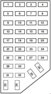
Ford Ranger - fuse box passanger - compartment fuse panel
Ford Ranger – fuse box passanger – compartment fuse panel
Number Ampere rating [A] Description
1 7,5 Power Mirror
2
3 15 Parking lamp
4 10 Left Headlamp
5 10 Data Link Connector (DLC)
6 7,5 Air Bag System, Blower Relay, EATC
7 7,5 Illumination Switches
8 10 Right Headlamp, Foglamp Relay, DRL
9 10 Anti-lock System
10 7,5 Speed Control, Generic Electronic Module (GEM), A/C System, Brake Interlock
11 7,5 Instrument Cluster, Warning Lamps
12 10 Front Wash System, Power Windows
13 15 PCM System, Stoplamps, AWD, Anti-lock System, Speed Control
14 20 Anti-Lock System
10 Anti-Lock System
15 7,5 Air Bag, Alternator
16 30 Front Wiper
17 25 Cigar Lighter
15 Cigar Lighter
18 15 A/C System
19 25 PCM System, Ignition Coil
20 7,5 Anti-Theft, Generic Electronic Module (GEM), Radio
21 15 Hazard Lamps
22 10 Turn Signals
23
24 10 Starter, Anti-Theft
25 7,5 Speedometer, Generic Electronic Module (GEM)
26 10 4R44E/4R55E/4R7OW/5R55E Overdrive, DRL System, Backup Lamps
27 10 Under Hood Lamp, Map Lamps, Glove Box Lamp, Dome Lamp, Visor Lamps, 4×4 System
28 7,5 Generic Electronic Module (GEM)
29 10 Audio System
30
31
32
33 15 Headlamps, Daytime Running Lamps (DRL) Module, Instrument Cluster
34
35
36

Engine Compartment Fuse Box

Ford Ranger - fuse box engine - compartment fuse panel
Ford Ranger – fuse box engine – compartment fuse panel
Number Ampere rating [A] Description
Maxi fuses
1
2 30 PCM Power
3 20 Fuel System, Anti-Theft System
4 20 Headlamps
5 30 ABS system
6 30 ABS system
7
8 20 Parking Lamps
9 40 Blower Motor
10 20 Power Locks, Power Windows, Power Seat
11 20 PCM Memory, Horn
12
13 50 Instrument Panel Fuse
14 50 Ignition
Mini fuses
1 20 JBL System
2 30 Power Point
3 15 HEGO
4 20 4 Wheel System
10 Air Bag System
5 15 PCM Memory Power
6 15 Alternator system
7 10 Air Bag System
20 4 Wheel System
8 15 DRL/Fog Lamps/Off-Road Lamps
Relay
1 Wiper Run Relay
2 Horn Relay
3 Fog Lamp Relay
4 WOT A/C Relay
5 PCM Power Relay
6 Fuel Pump Relay
7 Wiper HI/LO Relay
Diode
1 ABS diode
2 PCM diode
Resistor
1 RABS Resistor

WARNING: Terminal and harness assignments for individual connectors will vary depending on vehicle equipment level, model, and market.

Mazda MPV LW (1999 – 2006) – fuse box diagram

Mazda MPV LW (1999 – 2006) – fuse box diagram

Year of production: 1999, 2000, 2001, 2002, 2003, 2004, 2005, 2006

Fuse block (Engine compartment)

Mazda MPV - fuse box - engine compartment
Mazda MPV LW – fuse box –
engine compartment
Description Ampere rating [A] Description
1 DEFOG 40 Rear window defroster
2 BTN 60 STOP, HAZARD, ROOM, D.LOCK and DRL fuses
3 ABS 60 2002-2006: Antilock brake system
COOLING FAN 1 30 1999-2001: Cooling fan
4 FAN1 30 2002-2006: Cooling fan
HEATER 40 1999-2001: Heater
5 FAN2 30 2002-2006: Cooling fan
R.HEAT 30 1999-2001: Rear heater
6 HEATER 40 2002-2006: Heater
IG KEY1 40 1999-2001: METER, ENGINE and WIPER fuses
7 R.HEAT 30 2002-2006: Rear heater
IG KEY2 40 1999-2001: A/C, P.WIND, SUN ROOF and R.WIP fuses
8 IG KEY2 40 2002-2006: A/C, P.WIND, SUN ROOF and R.WIP fuses
COOLING FAN 2 30 1999-2001: Cooling fan
9 A/C 10 Air conditioner
10 TAIL 15 Taillights
11 A/C PWR 15 2002-2006: Inverter
12 HORN 15 Horn
13 FOG 15 Fog lights
14 EEC 5 2002-2006: For protection of various circuits
15 HEAD L 15 Headlight-left
16 HEAD R 15 Headlight-right
17 HID L 20
18 HID R 20
19 IG KEY1 60 2002-2006: METER, ENGINE and WIPER fuses
ABS 60 1999-2001: Antilock brake system
20 EGI INJ 30 Engine control system
21 FUEL PUMP 20 2002-2006: Fuel pump
22 MAIN 120 For protection of all circuits

Passenger Compartment Fuse Box

Mazda MPV - fuse box - driver's side
Mazda MPV – fuse box –
driver’s side
Description Ampere rating [A] Description
1 WIPER 20 1999-2001: Windshield wipers and washer
P. WIND 30 2002-2005: Power windows
P. WIND 40 2006: Power windows
2 P. WIND 30 1999-2001: Power windows
WIPER 20 2002-2006: Windshield wipers and washer
3 SUN ROOF 15 Moonroof
4 R.WIP 10 Rear window wiper and washer
5 SEAT 15 1999-2001: Seat
SEAT 20 2002-2006: Seat
6 M.DEF 10 Mirror defroster
7 A/C 10 Air conditioner
8 DRL 10 Day running lights
9
10 H/CLEAN 20 Headlight cleaning module
11
12 HAZARD 10 Hazard warning flashers
13 ROOM 10 1999-2001: Interior lights, Luggage compartment light
ROOM 15 2002-2006: Overhead lights, Map lights, Luggage compartment light
14 AUX POWER 15 1999-2001: Accessory socket
AUX POWER 25 2002-2006: Accessory socket
15 CLOSER LH 15 1999-2001: Slide door closer, LH
CLOSER LH 20 2002-2006: Slide door closer, LH
16 AUDIO 10 Audio system
17 D.LOCK 30 Power door locks
18 P/SEAT 30 2002-2006: Power seat
19 ENGINE 10 Engine control system
20 METER 10 Instrument cluster
21 STOP 15 Brake lights
22 CLOSER RH 15 1999-2001: Slide door closer, RH
CLOSER RH 20 2002-2006: Slide door closer, RH
23 ACC. DELAY 30 Power windows delay
24 METER 15 Instrument cluster, INH switch
25 ST.SIGN 10 Starter signal
26 CIGAR 15 1999-2001: Lighter
CIGAR 25 2002-2006: Lighter
27
28

WARNING: Terminal and harness assignments for individual connectors will vary depending on vehicle equipment level, model, and market.

Ford Ranger (1983 – 1992) – fuse box diagram

Ford Ranger (1983 – 1992) – fuse box diagram

Year of production: 1983, 1984, 1985, 1986, 1987, 1988, 1989, 1990, 1991, 1992

Passenger Compartment Fuse Panel

Ford Ranger - fuse box passanger - compartment fuse panel
Ford Ranger – fuse box passanger – compartment fuse panel
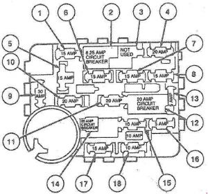
Number Ampere rating [A] Description
1 15 Dome/Courtesy Light, Radio
2 6 Circuit Breaker: Front Washer/Wiper
3
4 15 Four-Way Flash, Stoplights, Speed Control Inhibit
5 15 Turn Signals, Back-Up Lights, Turn Indicator, Rear Defrost Control, Brake Fluid Level Sensor
6 15 Rear Window Wiper and Washer
7 10 A/C Switches, Clutch Coil
8 20 Horns
9 30 Blower Motor
10 15 Parking Lights, License Lights, Engine Compartment Lamp, Lamps on Warning
11 15 Speed Control Amplifier & Radio, All Wheel Drive
12 20 Circuit Breaker: Cigar Lighters, Flash-to-Pass, Multi-Function Switch
13 10 Instrument Panel Illumination, Park/H Light Hot
14 20 Power Windows, Lumbar
30 1991-1992: Power Windows, Lumbar
15 20 R.A.B.S. Module
16 15 Premium Radio Amplifier
17 20 Cluster Warning Light, All Wheel Drive
15 Electric Shift Control, Lamps on Warning, Low Oil Level Relay, Instrument Cluster
18 10 HEGO Heater
15 Shift Indicator, Low Fuel Warning, Seat Belt Warning, Carburetor Circuit: Warning Indicator

Fuse Box In The Engine Compartment

Ford Ranger - fuse box diagram - engine compartment fuse panel
Ford Ranger – fuse box diagram – engine compartment fuse panel
Number Ampere rating [A] Description
1 60 Ignition
2 40 Electric Shift
3 30 E.E.C. Relay
4 50 Alternator
5 40 Rear Window Washer / Wiper / Defroster
6 30 Power Door Locks
7 40 Fuse Panel
8 60 Alternator
9 40 Headlamps

WARNING: Terminal and harness assignments for individual connectors will vary depending on vehicle equipment level, model, and market.