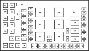
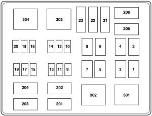
Toyota Cressida (1988 – 1998) – fuse box diagram

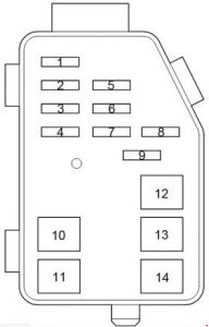
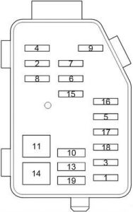
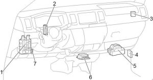
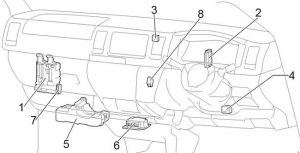
Toyota Cressida (1988 – 1998) – fuse box diagram

Year of production: 1988, 1989, 1990, 1991, 1992

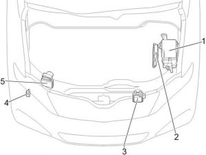
Engine Compartment
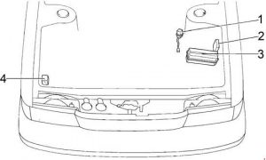
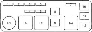
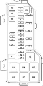
Toyota Cressida - fuse box diagram - engine compartment
Toyota Cressida – fuse box diagram – engine compartment
Number Description
1 Condenser Fan Relay
2 Headlight Cleaner Relay
3 Fuse Box
4 ABS Relay

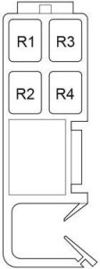
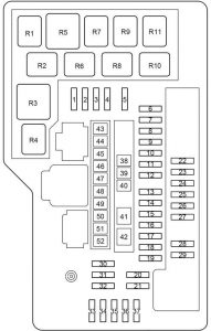
Engine Compartment Fuse Box

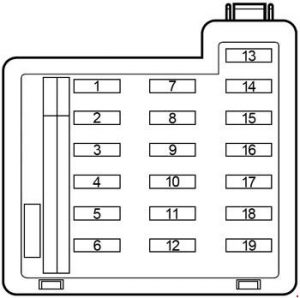
Toyota Cressida - fuse box diagram - engine compartment fuse box
Toyota Cressida – fuse box diagram – engine compartment fuse box
Description Ampere rating [A] Description
1 EFI 20 Fuel Pump, ISC Valve, Fuel Pump Resistor, Air Flow Meter, Check Connector, OX Sensor, TCCS ECU, VSV (for EGR)
2 DOME 20 Interior Light, Personal Light, Radio and Tape Player, Ignition Key Cylinder Light, Integration Relay, Auto Antenna Motor and Relay, Clock, Combination Meter, Door Courtesy Light, Door Courtesy SW, Door Warning Light, Luggage Compartment Light, Luggage Compartment Light SW, Theft Deterrent Computer, Vanity Mirror Light RH, Vanity Mirror Light LH
3
4 HEAD LH 15 Headlight LH, Dimmer SW, High Beam Indicator Light, Theft Deterrent Computer, Theft Deterrent Horn
5 HAZ-HORN 15 Horn, Hazard SW, Front Turn Signal Light, Horn SW, Turn Signal Indicator Light
6 HEAD RH 15 Headlight RH, Dimmer SW, High Beam Indicator Light
7
8 AM2 30 Ignition Switch, Injector, “IGN” fuse
9 AM1 40 Ignition Switch, Alternator, Headlight Cleaner Motor, Neutral Start Switch, TCCS ECU, Starter, Starter Relay, “ENGINE”, “ECU-IG”, “TURN”, “WIPER”, “GAUGE”, “CIG”, “RADIO”, “STARTER”, “POWER”, “DOOR LOCK”, “AUTOMATIC SHOULDER BELT” fuses
10 CDS FAN 30 A/C Condenser Fan Motor, A/C Condenser Fan Motor No.2, A/C Condenser Fan Relay
11 ALT 100 Alternator, Light Control Switch, Integration Relay, Theft Deterrent Computer, Taillight Relay, “DEFOG”, “HEATER”, “AM1”, “TAIL”, “STOP”, “ABS”, “CDS FAN” fuses
12 ABS 60 ABS Actuator, ABS Motor
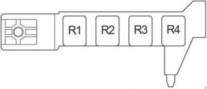
Relay
R1 EFI Main
R2 Headlight
R3 Horn
R4 Magnet Clutch

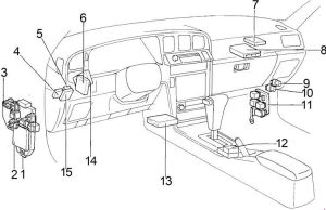
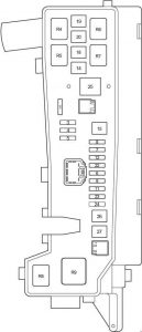
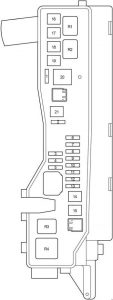
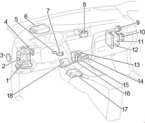
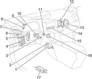
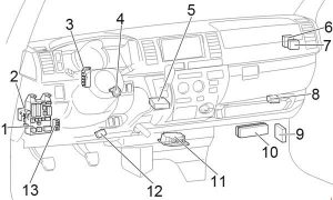
Passenger Compartment

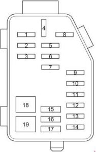
Toyota Cressida - fuse box diagram - passenger compartment
Toyota Cressida – fuse box diagram – passenger compartment
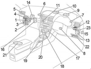
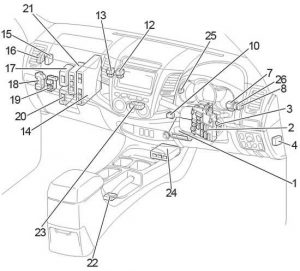
Number Description
1 Fuse Box
2 Integration Relay
3 Relay Box
4 Wiper Relay
5 Automatic Shoulder Belt Computer
6 Theft Deterrent Computer
7 PPS Computer
8 TCCS ECU
9 Blower Control Relay
10 Extra Hi Relay
11 Relay Box No.2
12 Shift Lock Control Computer
13 A/C System Amplifier
14 Cruise Control Computer
15 Door Lock Control Relay

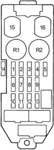
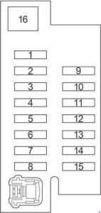
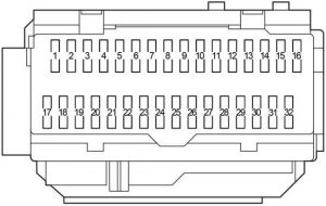
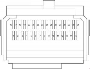
Passenger Compartment Fuse Box

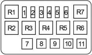
Toyota Cressida - fuse box diagram - passenger compartment fuse box
Toyota Cressida – fuse box diagram – passenger compartment fuse box
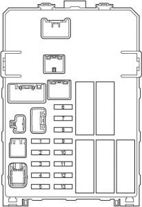
Number Fuse Ampere rating [A] Description
1 RADIO 7,5 Radio and Tape Player, Auto Antenna Motor and Relay, Remote Control Mirror SW, Remote Control Mirror RH, Remote Control Mirror LH
2 IGN 7,5 Alternator, Combination Meter, Charge Warning Light, TCCS ECU
3 ECU-B 15 ABS Computer
4 STOP 15 Stop Light, Stop Light SW, ABS Computer, Cruise Control Computer, High Mount Stop Light, Light Failure Sensor, Noise Filter (for Stop Light), Shift Lock Control Computer (Shift Lock Control SW. Shift Lock Solenoid), TCCS ECU
5 TAIL 15 Taillight and Rear Side Marker Light LH, Taillight and Rear Side Marker Light RH, Front Clearance Light, Licence Plate Light, A/T Indicator Light, Cigarette Lighter and Ashtray Illumination, Clock, Clock Light, Combination Meter Light, ECT Pattern Select SW, ECT Pattern Select SW Light, Glove Box Light, Glove Box Light SW, Hazard SW Light, Headlight Cleaner SW Light, Heater Control SW Light, O/D Main SW Light, Light Failure Sensor, Rheostat, Radio and Tape Player Light, Rear Window Defogger SW Light
6 CIG 15 Cigarette Lighter, Clock, Auto Antenna Motor and Relay, Door Lock Control Relay, Shift Lock Control Computer (Shift Lock Control SW. Shift Lock Solenoid), Theft Deterrent Computer
7 STARTER 7,5 Cold Start Injector, Combination Meter, Start Injector Time SW, Starter Cut Relay
8 ECU-IG 15 A/C System Amplifier, Air Vent Mode Control Servo Motor, ABS Computer, Blower Control Relay, Cruise Control Computer, Cruise Control SW, Extra Hi Speed Relay, Heater Control SW, Moon Roof Control Computer, PPS Computer, Recirc/Fresh Control Servo Motor, Shift Lock Control Computer (Shift Lock Control SW. Shift Lock Solenoid)
9
10 ENGINE 15 Alternator
11 WIPER 20 Wiper Motor, Wiper Control Relay, Wiper and Washer SW, Washer Motor, Headlight Cleaner Relay
12 TURN 7,5 Front Turn Signal Light, Turn Signal Indicator Light, Turn Signal SW, Hazard SW
13 GAUGE 7,5 Combination Meter, Back Up Light, ABS, A/T Indicator SW, Automatic Shoulder Belt Computer, Automatic Shoulder Belt Release Valve Warning Light, Auto Antenna Motor and Relay, A.B.S. Warning Light, A/T Indicator, Brake Fluid Level SW, Cruise Control Main Relay, Check Engine Warning Light, Cruise Control Indicator, ECT Pattern Select SW, ECT Pattern Indicator, Fuel Sender, Integration Relay, Light Failure Sensor, Oil Pressure SW, O/D Main SW, Parking Brake SW, Rear Window Defogger SW, Rear Light Warning Light, Seat Belt Warning Light, TCCS ECU, TDCL (Toyota Diagnostic Communication Link)
14 HTR-MIR 10 Mirror Heater
15 POWER 30 Moon Roof Control Computer, Moon Roof Motor, Power Window Master SW, Power Window Motor, Power Window SW, Power Seat Motor, Power Seat Control SW
16 DEFOG 30 Rear Window Defogger (+), Mirror Heater
Relay
R1 Taillight
R2 Defogger
Toyota Cressida - fuse box diagram - passenger compartment fuse box
Toyota Cressida – fuse box diagram – passenger compartment fuse box
Number Relay
R1 Integration Relay:
Unlock and Seat Belt Warning
Light Auto Turn-Off
Key Illuminated Entry System
Rear Window Defogger


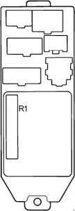
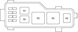
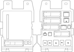
Passenger Compartment Relay Box

Toyota Cressida - fuse box diagram - passenger compartment relay box
Toyota Cressida – fuse box diagram – passenger compartment relay box
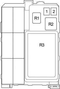
Description Ampere rating [A] Description
1 AUTOMATIC SHOULDER BELT 30 Automatic Shoulder Belt Computer, Automatic Shoulder Belt Motor
2 DOOR LOCK 20 Door Lock Control Relay, Door Lock Motor
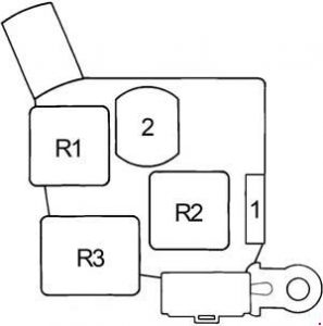
Relay
R1 Turn Signal Flasher
R2 Starter
R3 Power Main

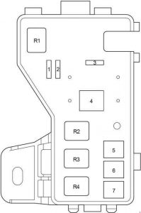
Passenger Compartment Relay Box No.2

Toyota Cressida - fuse box diagram - passenger compartment relay box
Toyota Cressida – fuse box diagram – passenger compartment relay box
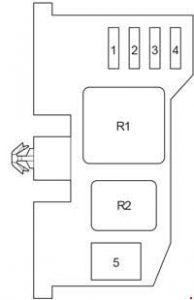
Number Fuse Ampere rating [A] Description
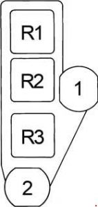
1 A/C 10 A/C Condenser Fan Relay, A/C Dual Pressure SW, A/C High Pressure SW, A/C Magnet Clutch, A/C Magnet Clutch Relay, Heater Control SW
2 HEATER 40 Blower Control Relay, Blower Motor
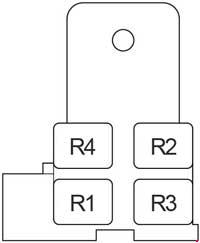
Relay
R1 Fuel Pump
R2 Heater
R3 Circuit Opening
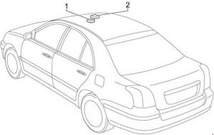
Toyota Cressida - fuse box diagram
Toyota Cressida – fuse box diagram
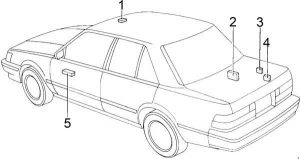
Number Relay
1 Moon Roof Control Computer
2 ABS Computer
3 Auto Antenna
4 Light Failure Sensor
5 Power Window Master SW


WARNING: Terminal and harness assignments for individual connectors will vary depending on vehicle equipment level, model, and market.

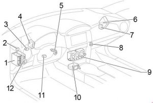
Toyota 86 (2012 – 2017) – fuse box diagram

Toyota 86 (2012 – 2017) – fuse box diagram

Year of production: 2012, 2013, 2014, 2015, 2016, 2017

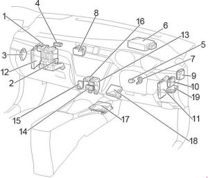
Passenger Compartment

LHD

Toyota 86 - fuse box diagram - passenger compartment LHD
Toyota 86 – fuse box diagram – passenger compartment LHD

RHD

Toyota 86 - fuse box diagram - passenger compartment RHD
Toyota 86 – fuse box diagram – passenger compartment RHD
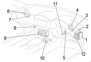
Number Description
1 Fuse Box / Main Body ECU
2 Headlight Leveling ECU
3 Turn Signal Flasher
4 Transmission Control ECU
5 Transponder Key Amplifier
6 ECM
7 Control Unit Relay
8 Relay Box
9 A/C Control
10 Airbag ECU
11 Steering Lock Actuator
12 Power Steering ECU

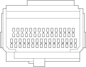
Passenger Compartment Fuse Box

Toyota 86 - fuse box diagram - passenger compartment fuse box
Toyota 86 – fuse box diagram – passenger compartment fuse box
Description Ampere rating [A] Description
1 P/POINT NO.1 15 Power outlet
2 RADIO 7,5 Audio system
3 SEAT HTR RH 10 Right-hand seat heater
4 SEAT HTR LH 10 Left-hand seat heater
5 ECU IG2 10 Engine control unit
6 GAUGE 7,5 Gauge and meters
7 AT UNIT 15 Transmission
8
9
10
11
12
13 AMP 15 Audio system
14
15 AM1 7,5 Starting system
16
17
18
19
20 ECU IG1 10 ABS, electric power steering
21 BK/UP LP 7,5 Back-up lights
22 FR FOG RH 10 Right-hand front fog light
23 FR FOG LH 10 Left-hand front fog light
24 HEATER 10 Air conditioning system
25 HEATER-S 7,5 Air conditioning system
26
27 OBD 7,5 On-board diagnosis system
28
29
30 STOP 7,5 Stop lights
31
32
33
34 DRL 10 Daytime running light system
35
36 TAIL 10 Tail lights
37 PANEL 10 Illumination
38 P/POINT NO.2 15 Power outlet
39 ECU ACC 10 Main body ECU, outside rear view mirrors

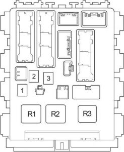
Passenger Compartment Relay Box

Toyota 86 - fuse box diagram - passenger compartment relay box
Toyota 86 – fuse box diagram – passenger compartment relay box
Description Ampere rating [A] Description
1
Relay
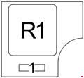
R1 Blower Motor
Toyota 86 - fuse box diagram
Toyota 86 – fuse box diagram
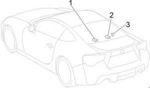
Number Description
1 Door Control Receiver
2 Tire Pressure Warning ECU and Receiver
3 Fuel Pump Control ECU

Engine Compartment

Toyota 86 - fuse box diagram - engine compartment
Toyota 86 – fuse box diagram – engine compartment
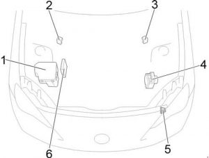
Number Description
1 Fuse Box
2 LHD: Fusible Link Block
3 RHD: Fusible Link Block
4 Brake Actuator
5 Headlight Cleaner Control Relay
6 Injector Driver (EDU)


Engine Compartment Fuse Box

Toyota 86 - fuse box diagram - engine compartment fuse box
Toyota 86 – fuse box diagram – engine compartment fuse box
Description Ampere rating [A] Description
1 A/B MAIN 15 SRS airbag system
2
3 IG2 7,5 Engine control unit
4 DOME 20 Interior light
5 ECU-B 7,5 Wireless remote control, main body ECU
6 HORN NO.2 7,5 Horn
7 HORN NO.1 7,5 Horn
8 H-LP LH LO 15 Left-hand headlight (low beam)
9 H-LP RH LO 15 Right-hand headlight (low beam)
10 H-LP LH HI 10 Left-hand headlight (high beam)
11 H-LP RH HI 10 Right-hand headlight (high beam)
12 ST 7,5 Starting system
13 ALT-S 7,5 Charging system
14 STR LOCK 7,5 Steering lock system
15 D/L 20 Power door lock
16 ETCS 15 Engine control unit
17 AT+B 7,5 Transmission
18 AM2 NO.2 7,5 Smart entry & start system
19
20 EFI (CTRL) 15 Engine control unit
21 EFI (HTR) 15 Multiport fuel injection system/sequential multiport fuel injection system
22 EFI (IGN) 15 Starting system
23 EFI (+B) 7,5 Engine control unit
24 HAZ 15 Turn signal lights, emergency flashers
25 MPX-B 7,5 Automatic air conditioning system, gauge and meters
26 F/PMP 20 Multiport fuel injection system/sequential multiport fuel injection system
27 IG2 MAIN 30 SRS airbag system, engine control unit
28 DCC 30 “ECU-B”, “DOME” fuses
29
30 PUSH-AT 7,5 Engine control unit
31
32 WIPER 30 Windshield wipers
33 WASHER 10 Windshield washer
34 D FL DOOR 25 Power window
35 ABS NO.2 25 ABS
36 D-OP 25
37 CDS 25 Electric cooling fan
38 D FR DOOR 25 Power window
39 RR FOG 10 Rear fog light
40 RR DEF 30 Rear window defogger
41 MIR HTR 7,5 Outside rear view mirror defoggers
42 RDI 25 Electric cooling fan
43 Spare fuse
44 Spare fuse
45 Spare fuse
46 Spare fuse
47 Spare fuse
48 Spare fuse
49 ABS NO.1 40 ABS
50 HEATER 50 Air conditioning system
51 INJ 30 Multiport fuel injection system/sequential multiport fuel injection system
52 H-LP WASHER 30 Headlight cleaners
53 AM2 NO.1 40 Starting system, engine control unit
54 EPS 80 Electric power steering
Relay
R1 (EFI MAIN1)
R2 Electric cooling fan (FAN NO.3)
R3 Heater
R4 (EFI MAIN3)
R5 (ETCS)
R6 Horn
R7 (H-LP)
R8 Dimmer (DIM)
R9 (EFI MAIN2)
R10 Fuel pump (C/OPEN)
R11 Inhibitor
R12 with Front Marker Light: (DRL RH)
without Front Marker Light: Daytime running light system (DRL)
R13 Starter (ST CUT)
R14 (IGS)
R15 Rear window defogger (RR DEF)
R16 Starter (ST)
R17 Ignition (IG2)
R18 with Front Marker Light: (DRL LH)
without Front Marker Light: Rear fog light (RR FOG)
R19 Electric cooling fan (FAN NO.2)
R20 (INJ)
R21 Outside rear view mirror defoggers (MIR HTR)
R22 Electric cooling fan (FAN NO.1)
R23 Windshield wipers (WIPER)

Fusible Link Block

Toyota 86 - fuse box diagram - fusible link box
Toyota 86 – fuse box diagram – fusible link box
Number Fuse Ampere rating [A] Description
1 ALT 140 Charging system
2 MAIN 80 Horn relay, headlight relay, dimmer relay, “ALT-S”, “ETCS”, “F/PMP”, “MPX-B”, “HAZ”, “EFI (+B)”, “EFI (IGN)”, “EFI (HTR)”, “EFI (CTRL)”, “AT+B”, “IG2 MAIN”, “AM2 NO.2”, “EPS”, “INJ”, “AM2 NO.1”, “H-LP WASHER”, “STR LOCK”, “DCC”, “D/L” fuses


WARNING: Terminal and harness assignments for individual connectors will vary depending on vehicle equipment level, model, and market.
Toyota Avensis T250 (2003- 2009) – fuse box diagram

Toyota Avensis T250 (2003- 2009) – fuse box diagram

Year of production: 2003, 2004, 2005, 2006, 2007, 2008, 2009

Passenger Compartment

LHD

Toyota Avensis - fuse box diagram - passenger compartment LHD
Toyota Avensis – fuse box diagram – passenger compartment LHD

RHD

Toyota Avensis - fuse box diagram - passenger compartment RHD
Toyota Avensis – fuse box diagram – passenger compartment RHD
Fuse Description
1 Fuse Box
2 Integration Relay
3 Circuit Opening Relay
4 Rear Fog Light Relay
5 Rear Window Defogger Relay
6 Relay Box
7 Turn Signal Flasher Relay
8 Transponder Key Amplifier
9 EPS ECU
10 Transponder Key Computer
11 Antenna Amplifier
12 Junction Block
13 Wiper Relay
14 Door Control Receiver
15 Headlight Beam Level Control ECU
16 Engine and ECT ECU (A/T)
Engine ECU (M/T)
17 A/C Control Assembly
18 Option Connector (Navigation ECU)
19 Shift Lock Control ECU
20 Airbag Sensor Assembly
21 Navigation ECU
22 Additional Fuse Box
23 RHD: Theft Deterrent ECU

Passenger Compartment Fuse Box

Toyota Avensis - fuse box diagram - passenger compartment fuse box
Toyota Avensis – fuse box diagram – passenger compartment fuse box
Fuse Ampere Circuit
1 IGN 10 SRS airbag system, gauge and meters, starting system, multiport fuel injection system/sequential multiport fuel injection system
2 S/ROOF 20 Sliding roof
3 RR FOG 7,5 Rear fog light
4 FR FOG 15 Front fog light, indicator light
5 AM1 25 Starting system, “CIG”, “RAD NO.1” fuses
6 PANEL 7,5 Instrument cluster lights, instrument panel lights, electronic controlled transmission, multi−information display, glove box light, console box light, headlight cleaner, front fog light, TOYOTA parking sssist
7 RR WIP 20 Rear wiper and washer
8 GAUGE2 7,5 Back–up light, headlight leveling system, turn signal and hazard warning light
9 CIG 15 Cigarette Lighter
10 HTR 10 Seat heaters, air conditioning system
11
12 RAD NO.1 7,5 Audio system, multi−information display, power rear view mirrors, gauge and meters, power outlet
13 PWR SEAT 30 Power seat
14 TAIL 10 Tail lights, parking lights, license plate lights, trunk light, automatic light control system, front fog light, rear fog light,
combination meter
15 OBD2 7,5 On−board diagnosis system
16 P/POINT 15 Power Outlet
17 DOOR 25 Power door lock system
18 WIP 25 Front wiper and washer, headlight cleaner
19 ECU-IG 7,5 Electric cooling fans, charging system, ABS, vehicle stability control system, electric power steering
20 S-HTR 20 Seat heaters
21 GAUGE1 10 Switch illumination, multi−information display, integration relay, gauge and meters, shift lock control system, electronic controlled transmission, auto anti-glare inside rear view mirror, windshield wipers, parking brake
22 STOP 15 Stop light, shift lock control system, ABS, high mounted stoplight, multiport fuel injection system/sequential multiport fuel injection system
Relay
R1
R2 HTR Heater
R3 SEAT HTR Seat Heater
R4 IG1 Ignition
R5 TAIL Taillight

Passenger Compartment Additional Fuse Box

Toyota Avensis - fuse box diagram - passenger compartment additional fuse box
Toyota Avensis – fuse box diagram – passenger compartment additional fuse box
Fuse Ampere Circuit
1
2 P-RR P/W 20 Power window
3 P-FR P/W 20 Power window
4 D-RR P/W 20 Power window
5 D-FR P/W 20 Power window
6 ECU-B 1 7,5 Multi–mode manual transmission
7 FUEL OPN 10 Fuel filler door opener
8 FR DIC 20 Front window deicer, “MIR HTR” fuse
9
10 DEF I/UP 7,5 Air conditioning system
11 ST 7,5 Multiport fuel injection system/sequential multiport fuel injection system, multi-information display, starting system
12 MIR HTR 10 Outside rear view mirror defogger
13 RAD NO.2 15 Audio system, multi−information display
14 DOME 7,5 Interior light, personal lights, foot lights, door courtesy lights, trunk light, vanity lights
15 ECU-B 2 7,5 Air conditioning system, wireless door lock control
16 PWR SEAT 30 Power seat

Passenger Compartment Relay Box

LHD

Toyota Avensis - fuse box diagram - passenger compartment relay box LHD
Toyota Avensis – fuse box diagram – passenger compartment relay box LHD

RHD

Toyota Avensis - fuse box diagram - passenger compartment relay box RHD
Toyota Avensis – fuse box diagram – passenger compartment relay box RHD
Number Relay
R1 Front window deicer (FR DEICER)
R2 Power Outlet (P/POINT)
R3 Front Fog Light (FR FOG)
R4 Starter (ST)

Sedan

Toyota Avensis - fuse box diagram - sedan
Toyota Avensis – fuse box diagram – sedan

Liftback

Toyota Avensis - fuse box diagram - liftback
Toyota Avensis – fuse box diagram – liftback

Wagon

Toyota Avensis - fuse box diagram - wagon
Toyota Avensis – fuse box diagram – wagon
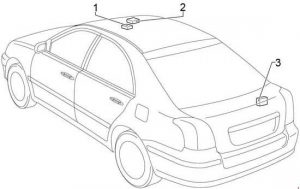
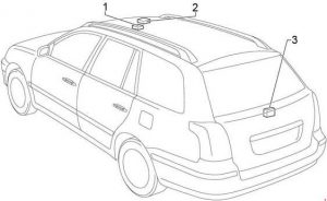
Number Decription
R1 Telephone Microphone Amplifier
R2 Moon Roof Control Relay and Motor
R3 Rear Wiper Motor and Relay

Engine Compartment

1AZ-FSE, 1AZ-FE, 1ZZ-FE, 3ZZ-FE

Toyota Avensis - fuse box diagram - engine compartment
Toyota Avensis – fuse box diagram – engine compartment

1CD-FTV

Toyota Avensis - fuse box diagram - engine compartment
Toyota Avensis – fuse box diagram – engine compartment
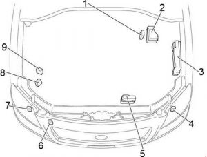
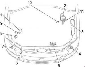
Number Description
1 Electronic Driver Unit
2 Additional Fuse Box
3 Fuse Box
4 Headlight Control ECU LH
5 Relay Box
6 Headlight Cleaner Control Relay
7 Headlight Control ECU RH
8 Skid Control ECU with Actuator (with VSC)
9 Skid Control ECU with Actuator (without VSC)
10 Glow Plug Relay
11 Power Heater Assembly

Engine Compartment Fuse Box

1AZ-FSE, 1AZ-FE, 1ZZ-FE, 3ZZ-FE

Toyota Avensis - fuse box diagram - engine compartment fuse box
Toyota Avensis – fuse box diagram – engine compartment fuse box

1CD-FTV

Toyota Avensis - fuse box diagram - engine compartment fuse box
Toyota Avensis – fuse box diagram – engine compartment fuse box
Number Fuse Ampere rating [A] Description
1
2 VSC 25 1CD–FTV: ABS, VSC
ABS 25 1CD–FTV: ABS
3
4
5
6 ALT-S 7,5 Charging system
7 DCC 30 “ECU-B NO.2”, “DOME”, “RAD NO.2” fuses
8 AM2 30 Starting system, “ST”, “IGN” fuses
9 HAZARD 10 Turn signal and hazard warning light
10 F-HTR 25 1CD–FTV: Fuel heater
11 HORN 15 Horn
12 EFI 20 Multiport fuel injection system/sequential multiport fuel injection system, “EFI NO.1”, “EFI NO.2” fuses
13 PWR HTR 25 1CD–FTV:Power heater
14 RR DEF 30 Rear windshield defogger
15 MAIN 40 Headlight cleaner, headlight, “H-LP HI LH”, “H-LP HI RH”, “H-LP  LH”, “H-LP  RH” fuses
16 AM1 NO.1 50 1CD–FTV: “ACC”, “CIG”, “RAD NO.1”, “ECU-B NO.1”, “FL P/W”, “FR P/W”, “RL P/W”, “RR P/W”
17 H/CLN 30 Headlight Cleaner
18 HTR 40 Air conditioner, heater
19 CDS 30 Electric cooling fan
20 RDI 40 1CD–FTV, 1ZZ-FE, 3ZZ-FE: Electric cooling fan
30 1AZ-FE, 1AZ-FSE: Electric cooling fan
21 VSC 50 1CD–FTV: ABS, VSC
ABS 40 1CD–FTV: ABS
22 IG2 15 1AZ-FSE, 1AZ-FE, 1ZZ-FE, 3ZZ-FE: Starting system, multiport fuel injection system/sequential multiport fuel injection system
23 THROTTLE 10 1AZ-FSE, 1AZ-FE, 1ZZ-FE, 3ZZ-FE: Electronic throttle control system
ETCS 10 1AZ-FSE, 1AZ-FE, 1ZZ-FE, 3ZZ-FE: Electronic throttle control system
24 A/F 20 1AZ-FSE, 1AZ-FE: Air fuel ratio sensor
25 1AZ-FSE, 1AZ-FE, 1ZZ-FE, 3ZZ-FE: –
26 1AZ-FSE, 1AZ-FE, 1ZZ-FE, 3ZZ-FE: –
27 EMPS 50 1ZZ-FE, 3ZZ-FE: Electric power steering
Relay
R1 EFI MAIN 1CD–FTV: Engine control unit
R2 EDU 1CD–FTV: Engine control unit
R3 FAN NO.3 1CD–FTV: Electric cooling fan
R4 FAN NO.1 Electric cooling fan
R5 FAN NO.2 1AZ-FSE, 1AZ-FE, 1ZZ-FE, 3ZZ-FE: Electric cooling fan
R6 1AZ-FSE, 1AZ-FE, 1ZZ-FE, 3ZZ-FE:
R7 FAN NO.3 1AZ-FSE, 1AZ-FE, 1ZZ-FE, 3ZZ-FE: Electric cooling fan
R8 1AZ-FSE, 1AZ-FE, 1ZZ-FE, 3ZZ-FE:  –
R9 EMPS 1ZZ-FE, 3ZZ-FE: Electric power steering

Engine Compartment Relay Box

Toyota Avensis - fuse box diagram - engine compartment relay box
Toyota Avensis – fuse box diagram – engine compartment relay box
Number Fuse Ampere rating [A] Description
1 H-LP HI LH 10 Left-hand headlight (high beam)
2 H-LP HI RH 10 Right-hand headlight (high beam), gauge and meters
3 H-LP LH 15 Left-hand headlight (low beam)
4 H-LP RH 15 Right-hand headlight (low beam)
Relay
R1 HORN Horn
R2 F-HTR Fuel Heater
R3 H-LP Headlight
R4 DIM Dimmer
R5 FAN NO.2 Electric cooling fan

Engine Compartment Additional Fuse Box (1CD-FTV)

Toyota Avensis - fuse box diagram - engine compartment relay additional box
Toyota Avensis – fuse box diagram – engine compartment relay additional box
Fuse Ampere Circuit
1
2 HTR2 50 Power heater
3 HTR1 50 Power heater
4 GLOW 80 Glow plug
5 ALT 140 IG1 Relay, TAIL Relay, SEAT HTR Relay, “H-LP CLN”, “AM1 NO.1”, “RDI”, “CDS”, “VSC” (50A), “VSC” (25A), “ABS” (40A), “ABS” (25A), “H/CLN”, “RR DEF”, “GLOW”, “HTR NO1”, “HTR NO2”, “RFGHTR”, “AM1 NO.2”, “RR FOG”, “S/ROOF”, “STOP”, “P/POINT”, “FR FOG”, “OBD2”, “DOOR” fuses
RELAY
R1
R2 HTR2 Power heater
R3 HTR1 Power heater

Engine Compartment Additional Fuse Box (1AZ-FSE, 1AZ-FE, 1ZZ-FE, 3ZZ-FE)

Toyota Avensis – fuse box diagram – engine compartment additional fuse box (1AZ-FSE, 1AZ-FE, 1ZZ-FE, 3ZZ-FE)
Number Fuse Ampere rating [A] Description
1 EFI NO.1 10 Multiport fuel injection system/sequential multiport fuel injection system
2 EFI NO.2 7,5 Emission control system
3 VSC 20 ABS, VSC
ABS 25 ABS
4 ALT 100 1ZZ-FE, 3ZZ-FE: “AM1 NO.1”, “H-LP CLN”, “ABS” (25A), “VSC” (25A), “ABS” (40A), “VSC” (50 A), “CDS”, “RDI”, “HTR”, “RR DEF”, “RR FOG”, “FR FOG”, “AM1”, “DOOR”, “STOP”,  “OBD2”,  “S/ROOF”, “PWR SEAT”, “P/POINT”, “TAIL”, “PANEL”, “RR WIP”, “ECU-IG”, “WIP”, “GAUGE2”, “GAUGE1”, “HTR” ,”S-HTR” fuses
120 1AZ-FSE, 1AZ-FE: “AM1 NO.1”, “H-LP CLN”, “ABS” (25A), “VSC” (25A), “ABS” (40A), “VSC” (50 A), “CDS”, “RDI”, “HTR”, “RR DEF”, “RR FOG”, “FR FOG”, “AM1”, “DOOR”, “STOP”,  “OBD2”,  “S/ROOF”, “PWR SEAT”, “P/POINT”, “TAIL”, “PANEL”, “RR WIP”, “ECU-IG”, “WIP”, “GAUGE2”, “GAUGE1”, “HTR” ,”S-HTR” fuses
5 VSC 40 ABS, VSC
ABS 40 ABS
6 AM1 NO.1 50 “PWR SEAT”, “FR DIC”, “FUEL OPN”, “ECU-B 1″, P-RR P/W”, “P-FR P/W”, “D-RR P/W”, “D-FR P/W” fuses
7 H-LP CLN 30 Headlight cleaner
Relay
R1 INJ Injector
R2 EFI Engine control unit
R3 IG2 Ignition
R4 A/F Air fuel ratio sensor

WARNING: Terminal and harness assignments for individual connectors will vary depending on vehicle equipment level, model, and market.

Toyota Avensis T270 (2009- 2017) – fuse box diagram

Toyota Avensis T270 (2009- 2017) – fuse box diagram

Year of production: 2009, 2010, 2011, 2012, 2013, 2014, 2015, 2016, 2017

Passenger Compartment

LHD

Toyota Avensis - fuse box diagram - passenger compartment LHD
Toyota Avensis – fuse box diagram – passenger compartment LHD

RHD

Toyota Avensis - fuse box diagram - passenger compartment RHD
Toyota Avensis – fuse box diagram – passenger compartment RHD
Fuse Description
1 Fuse Box / Main Body ECU
2 Additional Fuse Box
3 Headlight Swivel ECU (with AFS)
Headlight Leveling ECU (without AFS)
4 Junction Connector
5 Steering Lock Actuator
6 Power Steering ECU
7 Transponder Key Amplifier
8 Junction Block
9 Junction Block
10 Windshield Wiper Relay
11 Power Management Control ECU
12 Engine Stop & Start ECU
13 Relay Box No.1
14 Junction Connector
15 Junction Connector
16 Relay Box No.2
17 Airbag ECU
18 Air Conditioning Amplifier
19 RHD: Double Lock Door Control Relay

Passenger Compartment Fuse Box

Toyota Avensis - fuse box diagram - passenger compartment fuse box
Toyota Avensis – fuse box diagram – passenger compartment fuse box
Fuse Ampere Circuit
1 AM1 7,5 Starting system, “ACC”, “CIG”, “ECU-IG NO.2”, “HTR-IG”, “WIPER”, “RR WIPER”, “WASHER”, “ECU-IG NO.1”, “ECU-IG NO.3”, “SEAT HTR” fuses
2 FR FOG 15 Before Feb. 2013, from May 2015: Front fog lights
7,5 Feb. 2013 – May 2015: Front fog lights
3 DRL 7,5 Daytime running light system
4 ACC-B 25 “CIG”, “ACC” fuses
5 DOOR 25 Power door lock system
6
7 STOP 10 Stop lights, high mounted stoplight, anti-lock brake system, VSC, multiport fuel injection system/sequential multiport fuel injection system, automatic transmission, shift lock system, starting system
8 OBD 7,5 On-board diagnosis system
9 ECU-IG NO.2 10 Back-up lights, charging system, emergency flashers, rear window defogger, “PASSENGER AIRBAG” indicator, air conditioning system, AFS, rear view monitor, Toyota parking assist-sensor
10 ECU-IG NO.1 10 Main body ECU, smart entry & start system, electric cooling fan(s), shift lock system, panoramic roof shade, auto anti-glare inside rear view mirror, anti-lock brake system, steering sensor, yaw rate & G sensor, VSC, headlight cleaner, precrash safety system, LKA, driver support system
11 WASHER 15 Windshield washers, rear window washer
12 RR WIPER 15 Rear window wiper
13 WIPER 30 Windshield wipers, rain sensing windshield wipers
14 HTR-IG 10 Air conditioning system
15 SEAT HTR 15 Before May 2015: Seat heaters
20 From May 2015: Seat heaters
16 METER 7,5 Gauges and meters
17 IGN 7,5 Steering lock system, SRS airbag system, multiport fuel injection system/sequential multiport fuel injection system, automatic transmission, starting system
18 RR FOG 7,5 Rear fog light
19
20 TI&TE 30 Tilt & telescopic steering
21 MIR HTR 10 Outside rear view mirror defoggers
22
23 ACC 7,5 Outside rear view mirrors, shift lock system, audio system, main body ECU, power outlet
24 CIG 15 Cigarette lighter
25 SHADE 20 Panoramic roof shade
26 RR DOOR 20 Power windows (rear right)
27 RL DOOR 20 Power windows (rear left)
28 P FR DOOR 20 Power windows (passenger side)
29 ECU-IG NO.3 10 Toyota parking assist-sensor, AFS, windshield wiper de-icer, electric parking brake, pre-crash seat belt, paddle shift switch, tilt & telescopic steering, electric power steering
30 PANEL 7,5 Switch illumination, instrument cluster lights, glove box light, steering switches, main body ECU
31 TAIL 10 Front position lights, tail lights, license plate lights, rear fog light, front fog lights, manual headlight leveling dial, instrument panel lights, air conditioning system switch, audio system, multidrive or automatic transmission shift lever illumination, glove box light, airbag manual on-off system, emergency flashers, cigarette lighter, “AFS OFF” switch, speed limiter switch, electric parking brake switch, steering switch, VSC OFF switch, Toyota parking assist-sensor switch, “LKA” switch, seat heater switch, “SPORT” switch, outside rear view mirror switches, fuel filler door opener switch
Toyota Avensis - fuse box diagram - passenger compartment fuse box
Toyota Avensis – fuse box diagram – passenger compartment fuse box
Fuse Ampere Circuit
1 POWER 30 Power windows (driver side)
2 DEF 40 Rear window defogger, “MIR HTR” fuse
3 PWR SEAT RH 30 Power seat, lumber support
RELAY
R1 Ignition (IG1)
R2
R3 LHD (before May 2015): Turn signal flasher

Passenger Compartment Additional Fuse Box

Toyota Avensis - fuse box diagram - passenger compartment additional fuse box
Toyota Avensis – fuse box diagram – passenger compartment additional fuse box
Fuse Ampere Circuit
1 WIPER NO.2 7,5 Charging system, driver support system ECU
2

Passenger Compartment Relay Box No.1

Toyota Avensis - fuse box diagram - passenger compartment relay box
Toyota Avensis – fuse box diagram – passenger compartment relay box
Number Relay
R1 Before Jun. 2010: Front fog light (FR FOG)
From Oct. 2016: Interior lights (DOME CUT)
R2
R3 Before Nov. 2011: Panel
From Nov. 2011: Daytime running light system (DRL)
R4 Power outlet (ACC SOCKET)

Passenger Compartment Relay Box No.2

Toyota Avensis - fuse box diagram - passenger compartment relay box
Toyota Avensis – fuse box diagram – passenger compartment relay box
Number Description
R1 Starter (ST)
R2 Rear fog light (RR FOG)
R3 Accessory (ACC)
R4 Jun. 2010 – May 2015: Front fog light (FR FOG)
From Oct. 2016: Windshield wiper de-icer(FR DEICER)

Sedan

Toyota Avensis - fuse box diagram - sedan
Toyota Avensis – fuse box diagram – sedan

Wagon

Toyota Avensis - fuse box diagram - wagon
Toyota Avensis – fuse box diagram – wagon
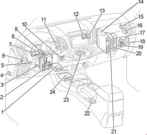
Number Description
1 Pre-Crash Safety City Sensor
2 Tire Pressure Warning ECU and Receiver
3 Door Control Receiver
4 Parking Brake ECU
5 Junction Connector
6 Sliding Roof Control ECU

Engine Compartment

Toyota Avensis - fuse box diagram - engine compartment
Toyota Avensis – fuse box diagram – engine compartment
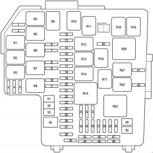
Number Description
1 Skid Control ECU
2 Fuse Box
3 ECM
4 Glow Plug Controller
5 Glow Plug Relay
6 Transmission Control ECU
7 Headlight Cleaner Control Relay
8 Injector Driver
9 LHD: Relay Box
10 RHD: Relay Box

Engine Compartment Fuse Box

Toyota Avensis - fuse box diagram - engine compartment fuse box
Toyota Avensis – fuse box diagram – engine compartment fuse box

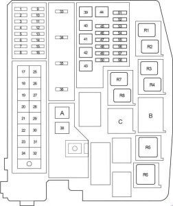
A

Toyota Avensis - fuse box diagram - engine compartment fuse box A
Toyota Avensis – fuse box diagram – engine compartment fuse box A
Toyota Avensis - fuse box diagram - engine compartment fuse box B
Toyota Avensis – fuse box diagram – engine compartment fuse box B
Toyota Avensis - fuse box diagram - engine compartment fuse box C
Toyota Avensis – fuse box diagram – engine compartment fuse box C
Fuse Ampere Circuit
1 DOME 10 Trunk/luggage compartment light, vanity lights, front door courtesy lights, personal/interior lights, personal lights, foot lights
2 RAD NO.1 20 Feb. 2014 – May 2015: Audio system
From May 2015: Audio system
15 Before Feb. 2014: Audio system
3 ECU-B 10 Gauges and meters, main body ECU, steering sensor, wireless remote control, smart entry & start system, tilt and telescopic steering
4 D.C.C
5 ECU-B2 10 Smart entry & start system, air conditioning system, power windows, power seat
6 EFI MAIN NO.2 7,5 Multiport fuel injection system/sequential multiport fuel injection system
7 DOOR NO.2 25 Before May 2015: Power door lock system
BODY ECU 7,5 From May 2015: Multiplex communication system
8 AMP 30 Audio system
9
10 STRG LOCK 20 Steering lock system
11 A/F 20 Before May 2015: Exhaust system
From May 2015: –
12 AM2 30 Starting system
13
14 TURN-HAZ 10 Turn signal lights, emergency flashers
15 ALT-S 7,5 Before May 2015: Charging system
From May 2015: –
16 AM2 NO.2 7,5 Starting system
17 HTR 50 Before May 2015: Air conditioning system
From May 2015: –
18 ABS NO.1 50 ABS, VSC
19 CDS FAN 30 Electric cooling fan
20 RDI FAN 40 Electric cooling fan
21 H-LP CLN 30 Headlight cleaner
22 IP/JB 120 From May 2015: “ECU-IG NO.2”, “HTR-IG”, “WIPER”, “RR WIPER”, “WASHER”, “ECU-IG NO.1”, “ECU-IG NO.3”, “SEAT HTR”, “AM1”, “DOOR”, “STOP”, “FR DOOR”, “POWER”, “RR DOOR”, “RL DOOR”, “OBD”, “ACC-B”, “RR FOG”, “FR FOG”, “DEF”, “TAIL”, “SUNROOF”, “DRL” fuses
23
24
25
26 H-LP MAIN 50 “H-LP LH LO”, “H-LP RH LO”, “H-LP LH HI”, “H-LP RH HI” fuses
27 P/I 50 “EFI MAIN”, “HORN”, “IG2”, “EDU” fuses
28 EFI MAIN 50 Before May 2015: Multiport fuel injection system/sequential multiport fuel injection system, “EFI NO.1”, “EFI NO.2” fuses
FUEL HTR 50 From May 2015: Fuel Heater
29 P-SYSTEM 30 Before May 2015: VALVEMATIC system
EPKB 50 From May 2015: Electric parking brake
30 GLOW 80 Before May 2015: Engine glow system
EPS 80 From May 2015: Electric power steering
31 EPS 80 Before May 2015: Electric power steering
GLOW 80 From May 2015: Engine glow system
32 ALT 140 Before May 2015: “RDI FAN”, “CDS FAN”, “H-LP CLN”, “PWR SEAT LH”, “FUEL OPN”, “ABS NO.1”, “ABS NO.2”, “FR DEICER”, “PSB”, “HTR”, “STV HTR”, “PWR OUTLET”, “HTR SUB NO.1”, “HTR SUB NO.2”, “HTR SUB NO.3”, “ECU-IG NO.2”, “HTR-IG”, “WIPER”, “RR WIPER”, “WASHER”, “ECU-IG NO.1”, “ECU-IG NO.3”, “SEAT HTR”, “AM1”, “DOOR”, “STOP”, “P FR DOOR”, “POWER”, “RR DOOR”, “RL DOOR”, “OBD”, “ACC-B”, “RR FOG”, “FR FOG”, “TI & TE”, “SHADE”, “PWR SEAT RH”, “DEF”, “TAIL”, “DRL” fuses
120 Before May 2015: “RDI FAN”, “CDS FAN”, “H-LP CLN”, “PWR SEAT LH”, “FUEL OPN”, “ABS NO.1”, “ABS NO.2”, “FR DEICER”, “PSB”, “HTR”, “STV HTR”, “PWR OUTLET”, “HTR SUB NO.1”, “HTR SUB NO.2”, “HTR SUB NO.3”, “ECU-IG NO.2”, “HTR-IG”, “WIPER”, “RR WIPER”, “WASHER”, “ECU-IG NO.1”, “ECU-IG NO.3”, “SEAT HTR”, “AM1”, “DOOR”, “STOP”, “P FR DOOR”, “POWER”, “RR DOOR”, “RL DOOR”, “OBD”, “ACC-B”, “RR FOG”, “FR FOG”, “TI & TE”, “SHADE”, “PWR SEAT RH”, “DEF”, “TAIL”, “DRL” fuses
From May 2015: 
33 IG2 15 Before May 2015: “IGN”, “METER” fuses
FUEL PUMP 30 From May 2015: Fuel pump
34 HORN 15 Horn
35 EFI MAIN 30 Before Nov. 2011: Multiport fuel injection system/sequential multiport fuel injection system, “EFI NO.1”, “EFI NO.2” fuses
FUEL OPN 10 From Nov. 2011: Fuel filler door opener
36 EDU 20 Before May 2015: Multiport fuel injection system/sequential multiport fuel injection system
IGT/INJ 15 Before May 2015: Multiport fuel injection system/sequential multiport fuel injection system
IG2 15 From May 2015: “IGN”, “METER” fuses
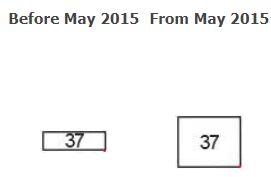
37 Before May 2015: 
EFI MAIN 50 From May 2015: “EFI NO.1”, “EFI NO.2”, “EFI NO.4” fuses
38 E-PKB 30 Before May 2015: Electric parking brake
BBC 40 From May 2015: Stop & Start system
39 HTR SUB NO.3 30 Before May 2015: Power heater
40
41 HTR SUB NO.2 30 Before May 2015: Power heater
42 HTR 50 From May 2015: Air conditioning system
43 HTR SUB NO.1 30 Before May 2015: Power heater
50 From May 2015: Power heater
44 PWR SEAT LH 30 Power seat, lumber support
45 STV HTR 25 Power heater
46 ABS NO.2 30 ABS, VSC
47 FR DEICER 20 Windshield wiper de-icer
48 FUEL OPN 10 Before May 2015: Fuel filler door opener
From May 2015: 
49 PSB 30 Before May 2015: Pre-crash seat belt
From May 2015: From May 2015 Production –
50 PWR OUTLET 15 Power outlet
51 H-LP LH LO 10 Before May 2015: 
Except HID: Left-hand headlight (low beam)
From May 2015: Left-hand headlight (low beam)
15 Before May 2015: 
HID: Left-hand headlight (low beam)
52 H-LP RH LO 10 Before May 2015: 
Except HID: Right-hand headlight (low beam)
From May 2015: Right-hand headlight (low beam)
15 Before May 2015: 
HID: Right-hand headlight (low beam)
53 H-LP LH HI 10 Left-hand headlight (high beam)
54 H-LP RH HI 10 Right-hand headlight (high beam)
55 EFI NO.1 10 Before May 2015: Multiport fuel injection system/sequential multiport fuel injection system, air flow meter, exhaust system
7,5 From May 2015: Multiport fuel injection system/sequential multiport fuel injection system, air flow meter, exhaust system
56 EFI NO.2 10 Before May 2015: Air intake system, air flow meter, exhaust system
15 From May 2015: Air intake system, air flow meter, exhaust system
57 IG2 NO.2 7,5 Before May 2015: Starting system
From May 2015: –
58 EFI NO.3 7,5 Before Nov. 2011: Multiport fuel injection system/sequential multiport fuel injection system
EFI NO.4 30 From Nov. 2011: Multiport fuel injection system/sequential multiport fuel injection system, “EFI NO.1”, “EFI NO.2” fuses
20 From May 2015: Multiport fuel injection system/sequential multiport fuel injection system, “EFI NO.1”, “EFI NO.2” fuses
59 CDS EFI 5 From May 2015: Electric cooling fan
60 EFI NO.3 7,5 From Nov. 2011: Multiport fuel injection system/sequential multiport fuel injection system
RDI EFI 5 From May 2015: Electric cooling fan
RELAY
R1 Before Nov. 2013: Windshield wiper de-icer / Stop light (FR DEICER/BRAKE LP)
From Nov. 2013: Electric Cooling Fan (FAN NO.2)
R2 Electric Cooling Fan (FAN NO.3)
R3 Before May 2015: Air fuel ratio sensor (A/F)
From May 2015: FR FOG Relay LH
R4 Before May 2015: Interior lights (DOME CUT)
From May 2015: FR FOG Relay RH
R5 Engine control unit (EFI MAIN)
R6 Headlight (H-LP)
R7 Before Nov. 2013: Electric Cooling Fan (FAN NO.2)
Nov. 2013 – Before Oct. 2016: Windshield wiper de-icer (FR DEICER)
From Oct. 2016: Dimmer
R8 Electric Cooling Fan (FAN NO.1)
R9 May 2015 – Oct. 2016: Interior lights (DOME CUT)
From Oct. 2016: (TSS C HTR)
R10 Before Nov. 2011: Fuel filler door opener (FUEL OPN)
R11 Before Nov. 2011: Dimmer
From Nov. 2011:
without AFS: Dimmer
From Nov. 2011:
with AFS: –
May 2015 – Oct. 2016: 
with fuel heater: Fuel Heater (FUEL HTR)
without fuel heater: –
R12 From Nov. 2011:
with AFS: Dimmer
May 2015 – Oct. 2016:
Dimmer

Engine Compartment Relay Box

Toyota Avensis - fuse box diagram - engine compartment relay box
Toyota Avensis – fuse box diagram – engine compartment relay box
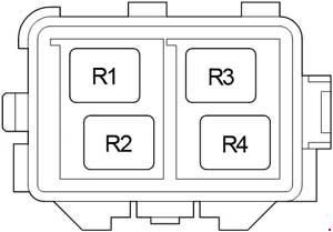
Number Relay
R1
R2 HTR SUB NO.1
R3 HTR SUB NO.2
R4 HTR SUB NO.3

WARNING: Terminal and harness assignments for individual connectors will vary depending on vehicle equipment level, model, and market.
Toyota Hilux (2004- 2015) – fuse box diagram

Toyota Hilux (2004- 2015) – fuse box diagram

Year of production: 2004, 2005, 2006, 2007, 2008, 2009, 2010, 2011, 2012, 2013, 2014, 2015

Passenger Compartment

LHD

Toyota Hilux - fuse box diagram - passenger compartment LHD
Toyota Hilux – fuse box diagram – passenger compartment LHD

RHD

Toyota Hilux - fuse box diagram - passenger compartment RHD
Toyota Hilux – fuse box diagram – passenger compartment RHD
Fuse Description
1 A/C Amplifier (with Air Conditioner)
Viscous Heater Amplifier (without Air Conditioner)
2 Fuse Box / Integration Relay
3 Transponder Key Amplifier
4 4WD Control ECU (Rear Differential Lock)
5 LHD: Tail Lamp Relay (Aug. 2006 – Jun. 2011)
6 LHD: Daytime Running Light Relay
7 Turn Signal Flasher
8 Magnet Clutch Relay
9 LHD:Tail Lamp Relay (Before Aug. 2006)
LHD:
Rear Fog Lamp Relay (From Aug. 2006)
10 Junction Connector
11 LHD: Tail Lamp Relay (From Jun. 2011)
12 PTC Heater Relay (No.2P)
13 PTC Heater Relay (No.1)
14 Engine ECU
15 Door Control Receiver
16 Theft Warning ECU
17 4WD Control ECU
18 Relay Box (From Jun. 2011)
19 Relay Box (Before Jun. 2011)
20 Turbo Motor Driver
21 Transmission Control ECU
22 Shift Lock Control ECU
23 A/C Control Assembly
24 Airbag Sensor Assembly Center
25 RHD: Tail Lamp Relay
26 RHD: Rear Fog Lamp Relay

Passenger Compartment Fuse Box

Toyota Hilux - fuse box diagram - passenger compartment - fuse box
Toyota Hilux – fuse box diagram – passenger compartment – fuse box
Fuse Ampere Circuit
1 INJ 15 Multiport fuel injection system/sequential multiport fuel injection system
2 OBD 7,5 On-board diagnosis system
3 STOP 10 Stop lights, high mounted stoplight, multiport fuel injection system/sequential multiport fuel injection system, ABS, TRC, VSC and shift lock control system
4 TAIL 10 Instrument panel light, front fog lights, headlight beam level control system, front position lights, tail lights, license plate lights, multiport fuel injection system/sequential multiport fuel injection system, multi-information display, daytime running light system and automatic headlight system
5 PWR OUT 15 Power outlet
6 ST 7,5 Starting system, gauges and meters and multiport fuel injection system/sequential multiport fuel injection system
7 A/C 10 Air conditioning system
8 MET 7,5 Gauges and meters and DPF system
9 CIG 15 Cigarette lighter
10 ACC 7,5 Audio system, power outlet, clock, power rear view mirror control system, shift lock control system and multi-information display
11 IGN 7,5 Multiport fuel injection system/sequential multiport fuel injection system, SRS airbags and fuel pump
12 WIP 20 Windshield wiper and washer
13 ECU-IG & GAUGE 10 Air conditioning system, charging system, rear differential lock system, ABS, TRC, VSC, emergency flashers, turn signal lights, back-up lights, multiport fuel injection system/sequential multiport fuel injection system, shift lock control system, rear window defogger, headlights, door courtesy switches, power door lock system, wireless remote control system, steering sensor, daytime running light system, cruise control, headlight cleaners, seat heaters, outside rear view mirror defoggers, multi-information display and passenger’s seat belt reminder light
Toyota Hilux - fuse box diagram - passenger compartment - fuse box
Toyota Hilux – fuse box diagram – passenger compartment – fuse box
Fuse Ampere Circuit
1 AM1 40 Rear differential lock system, ABS, TRC, VSC, “ACC”, “CIG”, “ECU-IG & GAUGE”, and “WIP” fuses
2 IG1 40 “PWR”, “S-HTR”, “4WD”, “DOOR”, “DEF” and “MIR HTR” fuses
RELAY
R1 Power outlet (PWR OUT)
R2 Heater (HTR)
R3 Integration relay

Passenger Compartment Relay Box (Before Jun. 2011)

Toyota Hilux - fuse box diagram - passenger compartment relay box before 2011
Toyota Hilux – fuse box diagram – passenger compartment relay box before 2011
Fuse Ampere Circuit
1 DOOR 25 Power door lock system and power windows
2 DEF 20 Rear window defogger and multiport fuel injection system/sequential multiport fuel injection system
3 S-HTR 15 Seat heaters
4 4WD 20 Rear differential lock system, ABS, TRC and VSC
5 PWR 30 Power windows
RELAY
R1 Ignition (IG1)
R2 Rear window defogger (DEF)

Passenger Compartment Relay Box (From Jun. 2011)

Toyota Hilux - fuse box diagram - passenger compartment relay box from 2011
Toyota Hilux – fuse box diagram – passenger compartment relay box from 2011
Fuse Ampere Circuit
1 MIR HTR 15 Before Nov. 2011: Outside rear view mirror defoggers
DOOR 25 From Nov. 2011: Power door lock system and power windows
2 DOOR 25 Before Nov. 2011: Power door lock system and power windows
DEF 20 From Nov. 2011: Rear window defogger and multiport fuel injection system/sequential multiport fuel injection system
3 DEF 20 Before Nov. 2011: Rear window defogger and multiport fuel injection system/sequential multiport fuel injection system
S-HTR 15 From Nov. 2011: Seat heaters
4 S-HTR 15 Before Nov. 2011: Seat heaters
4WD 20 From Nov. 2011: Rear differential lock system, ABS, TRC and VSC
5 4WD 20 Before Nov. 2011: Rear differential lock system, ABS, TRC and VSC
MIR HTR 15 From Nov. 2011: Outside rear view mirror defoggers
RELAY
R1 Outside rear view mirror defoggers (MIR HTR)
R2 Ignition (IG1)
R3 Rear window defogger (DEF)

Engine Compartment

LHD

Toyota Hilux - fuse box diagram - engine compartment LHD
Toyota Hilux – fuse box diagram – engine compartment LHD

RHD

Toyota Hilux - fuse box diagram - engine compartment RHD
Toyota Hilux – fuse box diagram – engine compartment RHD
Number Description
1 Fuse Box
2 Skid Control ECU with Actuator
3 Headlight Cleaner Control Relay
4 Glow Plug Controller
5 2TR-FE: Air Injection Control Driver
RHD:
1KD-FTV and 2KD-FTV (without DPF): Injector Driver (EDU)
LHD:
1KD-FTV and 2KD-FTV (with DPF): Injector Driver (EDU)
6 RHD:
1KD-FTV and 2KD-FTV (with DPF): Injector Driver (EDU)
LHD:
1KD-FTV and 2KD-FTV (without DPF): Injector Driver (EDU)

Engine Compartment Fuse Box

Toyota Hilux - fuse box diagram - engine compartment fuse box
Toyota Hilux – fuse box diagram – engine compartment fuse box

A

1TR-FE, 2TR-FE, 1GR-FE

Toyota Hilux - fuse box diagram - engine compartment relay box
Toyota Hilux – fuse box diagram – engine compartment relay box

1KD-FTV w/o DPF, 2KD-FTV w/o DPF, 5L-E

Toyota Hilux - fuse box diagram - engine compartment relay box
Toyota Hilux – fuse box diagram – engine compartment relay box

1KD-FTV w/ DPF, 2KD-FTV w/ DPF

Toyota Hilux - fuse box diagram - engine compartment relay box
Toyota Hilux – fuse box diagram – engine compartment relay box
Fuse Ampere Circuit
1 25 Spare fuse
2 15 Spare fuse
3 10 Spare fuse
4 FOG 7,5 Europe, Morocco:
From Aug. 2012 – Aug. 2013: Front fog lights
From Aug. 2013: Front fog lights
15 Before Aug. 2013: Front fog lights
Except Europe, Morocco:
From Aug. 2012 – Aug. 2013: Front fog lights
5 HORN 10 Horn
6 EFI 25 Multiport fuel injection system/sequential multiport fuel injection system
7
8 H-LP RL 20 Before Jun. 2011: Right-hand headlight (Low)
15 From Jun. 2011: Right-hand headlight (Low)
9 H-LP LL 20 Before Jun. 2011: Left-hand headlight (Low)
15 From Jun. 2011: Left-hand headlight (Low)
10 H-LP RH 20 Before Jun. 2011: Right-hand headlight (High) and right-hand headlight (Low)
15 From Jun. 2011: Right-hand headlight (High) and right-hand headlight (Low)
11 H-LP LH 20 Before Jun. 2011: Left-hand headlight (High) and left-hand headlight (Low)
15 From Jun. 2011: Left-hand headlight (High) and left-hand headlight (Low)
12 EFI NO.2 10 Multiport fuel injection system/sequential multiport fuel injection system
13 ECU-IG NO.2 10 Multiport fuel injection system/ sequential multiport fuel injection system
14 ECU-B 7,5 Before Aug. 2008: Door courtesy switches, power door lock system, wireless remote control system, steering sensor and headlights
10 From Aug. 2008: Door courtesy switches, power door lock system, wireless remote control system, steering sensor and headlights
15 RAD 15 Before Aug. 2013: Audio system
20 From Aug. 2013: Audio system
16 DOME 7,5 Interior lights, engine switch light, personal light, gauges and meters, clock, multi-information display, wireless remote control system, daytime running light system and fog light
17 A/F 20 Emission control system
18 ETCS 10 Multiport fuel injection system/ sequential multiport fuel injection system, electric throttle control system
19 ALT-S 7,5 Charging system
20 TURN-HAZ 15 Emergency flashers and turn signal lights
21
22 ECU-B NO.2 7,5 Air conditioning system
23 DCC 30 “ECU-B”, “DOME” and “RAD” fuses
24 PTC NO.1 50 Power heater
25 H-LP CLN 30 Before Jun. 2011: Headlight cleaners
PWR SEAT 30 Power seat
26 PTC NO.2 50 Europe:
From Aug. 2010 – Jun. 2011 (without Automatic A/C): Power heater
From Jun. 2011: Power heater
30 Europe:
Before Jun. 2011 (with Automatic A/C): Power heater
Before Aug. 2010 (without Automatic A/C): Power heater
Australia: Power heater
27 ABS NO.1 40 Before Aug. 2008: ABS, TRC and VSC
H-LP CLN 40 From Jun. 2011: Headlight cleaners
28 FR HTR 40 Before Aug. 2009: Air conditioning system, “A/C” fuse
50 From Aug. 2009: Air conditioning system, “A/C” fuse
29 ABS NO.2 30 ABS, TRC and VSC
30 ABS NO.1 40 From Aug. 2008: ABS, TRC and VSC
31 ALT 100 Charging system, “PWR SEAT”, “HLP CLN”, “FR HTR”, “AM1”, “IG1”, “PTC NO.1”, “PTC NO.2”, “PWR OUT”, “STOP”, “TAIL” and “OBD” fuses
32 GLOW 80 Engine glow system
33 BATT P/I 50 “FOG”, “HORN” and “EFI” fuses
34 AM2 30 Engine starter, “ST”, “IGN”, “INJ” and “MET” fuses
35 MAIN 40 “H-LP RH”, “H-LP LH”, “H-LP RL” and “H-LP LL” fuses
36 A/PUMP 50 Multiport fuel injection system/sequential multiport fuel injection system
RELAY
R1 Dimmer (DIM)
R2 Headlight (H-LP)
A
R1 Starter (ST)
R2 1TR-FE, 2TR-FE, 1GR-FE: Air fuel ratio sensor (A/F)
1KD-FTV w/o DPF, 2KD-FTV w/o DPF, 5L-E: Engine glow system (GLOW)
1KD-FTV w/ DPF, 2KD-FTV w/ DPF: Air fuel ratio sensor (A/F)
R3 1TR-FE, 2TR-FE, 1GR-FE: Fuel pump (F/PMP)
1KD-FTV w/ DPF, 2KD-FTV w/ DPF: –

WARNING: Terminal and harness assignments for individual connectors will vary depending on vehicle equipment level, model, and market.
Toyota Venza (2008 – 2017) – fuse box diagram

Toyota Venza (2008 – 2017) – fuse box diagram

Year of production: 2008, 2009, 2010, 2011, 2012, 2013, 2014, 2015, 2016, 2017

Passenger Compartment

Toyota Venza - fuse box diagram - passenger compartment
Toyota Venza – fuse box diagram – passenger compartment
Number Description
1 Center Airbag Sensor Assembly
2 Shift Lock Control ECU Sub-Assembly
3 Transponder Key Amplifier
4 Fuse Box / Main Body ECU
5 Headlight Leveling ECU
6 Relay Box
7 Power Steering ECU
8 Turn Signal Flasher
9 Junction Connector
10 Steering Lock Actuator
11 Junction Connector
12 A/C Amplifier
13 Power Management Control ECU
14 AWD ECU
15 Extension Module
16 Headlight Swivel ECU
17 Stereo Component Amplifier

Passenger Compartment Fuse Box

Toyota Venza - fuse box diagram - passenger compartment fuse box
Toyota Venza – fuse box diagram – passenger compartment fuse box
Number Fuse Ampere rating [A] Description
1 RR DOOR 25 2008-2009: Power windows
20 2010-2017: Power windows
2 RL DOOR 25 2008-2009: Power windows
20 2010-2017: Power windows
3 FR DOOR 25 2008-2009: Power windows
20 2010-2017: Power windows
4 FOG 15 Fog lights
5 OBD 7,5 On-board diagnosis system
6 FL DOOR 25 2008-2009: Power windows
20 2010-2017: Power windows
7 STOP 10 Stop lights, vehicle stability control system
8 RR FOG 10 Rear fog light
9
10 AM1 7,5 Starting system
11 ECU-B NO.2 7,5 Steering sensor, air conditioning system, power windows
12 4WD 7,5 Active Torque Control 4WD
13 SEAT HTR 20 Seat heaters
14 S/ROOF 25 Electric moon roof
15 TAIL 10 Side marker lights, tail lights, license plate light
16 PANEL 5 Emergency flashers, audio system, clock, instrument panel light control, glove box light, console box light, steering switches, outside rear view mirror defoggers, seat heaters, vehicle stability control system, shift lever ligh
17 ECU IG NO.1 10 Multiplex communication system, electric moon roof, power back door, seat heaters, Active Torque Control 4WD, audio system, Automatic High Beam
18 RR WASHER 15 Rear window washer
19 A/C NO.2 10 Air conditioning system
20 FR WASHER 20 Windshield washer
21 ECU IG NO.2 7,5 Vehicle stability control system, automatic headlight leveling system, yaw rate & G sensor, steering sensor, shift lock system, tire pressure warning system, automatic transmission, electric power steering
22 GAUGE NO.1 10 Entune Premium Audio with Navigation, back-up lights, charging system, emergency flashers, multi-information display
23 FR WIPER 30 Windshield wipers
24 RR WIPER 15 Rear window wiper
25
26 IGN 10 Multiport fuel injection system/sequential multiport fuel injection system, steering lock system, smart key system, SRS airbag system, front passenger occupant classification system
27 GAUGE NO.2 7,5 Gauges and meters, multi-information display, multiplex communication system
28 ECU-ACC 7,5 Power rear view mirrors
29 SHIFT LOCK 7,5 Shift lock system
30 PWR OUTLET NO.1 15 Power outlets
31 RADIO NO.2 7,5 Audio system
32 MIR HTR 10 Outside rear view mirror defoggers


Toyota Venza - fuse box diagram - passenger compartment fuse box
Toyota Venza – fuse box diagram – passenger compartment fuse box
Number Fuse Ampere rating [A]] Description
1 P/SEAT 30 Power windows
2
Relay
R1 Fog Lights
R2 Tail Lights
R3 Accessory Relay (ACC)
R4
R5 Ignition (IG1)

Passenger Compartment Relay Box

Toyota Venza - fuse box diagram - passenger compartment relay box
Toyota Venza – fuse box diagram – passenger compartment relay box
Number Description
R1 Interior lights (DOME CUT)
R2 Rear fog light (RR FOG)
R3
R4 Ignition (IG1 NO.2)


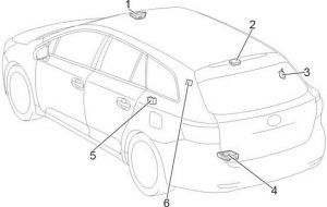
Number Description
1 Sliding Roof Control ECU
2 Outer Mirror Control ECU Assembly RH
3 Door Control Receiver
4 Junction Connector
5 Power Back Door Unit
6 Front Multiplex Network Door ECU (without Power Back Door)
7 Outer Mirror Control ECU Assembly LH

Engine Compartment

Toyota Venza - fuse box diagram - engine compartment
Toyota Venza – fuse box diagram – engine compartment
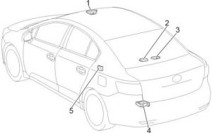
Number Description
1 Fuse Box
2 ECM
3 Transmission Control ECU
4 Headlight Cleaner Control Relay
5 Brake Actuator

Engine Compartment Fuse Box

Toyota Venza - fuse box diagram - engine compartment fuse box
Toyota Venza – fuse box diagram – engine compartment fuse box
Number Fuse Ampere rating [A] Description
1 DOME 7,5 Personal/interior lights, vanity lights, engine switch light, door courtesy lights, power back door, gauges and meters
2 ECU-B 10 Gauges and meters, clock, audio system, main body ECU, wireless remote control, smart key system, power back door, front passenger occupant classification system
3 RSE 10 2008-2012: Rear seat entertainment system
4 RADIO NO.1 15 2008-2010: Audio system, navigation system
20 2011-2017: Audio system, navigation system
5 DCC
6 RADIO NO.3 25 2008-2012: Audio system
AUDIO AMP 20 2013-2017: Audio system
7
8 IG2 25 “INJ NO.1”, “INJ NO.2” fuses, SRS airbag system
9
10 HAZ 15 2008-2012: Turn signal lights
TURN-HAZ 15 2013-2017: Turn signal lights
11 ETCS 10 Multiport fuel injection system/sequential multiport fuel injection system, electronic throttle control system
12 EFI NO.1 10 Smart key system, multiport fuel injection system/sequential multiport fuel injection system, automatic transmission
13 ALT-S 7,5 Charging system
14 AM2 7,5 Multiplex communication system, starting system
15 SEC-HORN 7,5 Theft deterrent
16 STR LOCK 20 Steering lock system
17 DOOR NO.1 20 Power door lock system
18
19 BI-XENON 10 2013-2017: Discharge headlights (high beam control)
20 EFI NO.3 10 Multiport fuel injection system/sequential multiport fuel injection system
21 EFI NO.2 15 Multiport fuel injection system/sequential multiport fuel injection system
22 EFI NO.4 20 1AR-FE: Air fuel ratio sensor
EFI MAIN 25 2GR-FE: “EFI NO.2”, “EFI NO.3” fuses
23
24 H-LP RH HI 15 Right-hand headlight (high beam)
25 H-LP LH HI 15 Left-hand headlight (high beam)
26 H-LP RH LO 15 Right-hand headlight (low beam)
27 H-LP LH LO 15 Left-hand headlight (low beam)
28 HORN 10 Horn
29 EFI MAIN 20 1AR-FE: “EFI NO.2”, “EFI NO.3” fuses
A/F 20 2GR-FE: Air fuel ratio sensor
30 INJ NO.2 15 Igniter system
31 INJ NO.1 15 Multiport fuel injection system/sequential multiport fuel injection system
32
33 AC 115V 15 2008-2012: Power outlet
MIRROR 10 2013-2017: Outside rear view mirrors (driving position memory)
34
35 DEICER 20 Windshield wiper de-icer
36
37
38 ST/AM2 30 Starting system
39
40
41 EPS 80 Electric power steering
42 ALT 120 Charging system, “HEATER”, “ABS NO.1”, “FAN MAIN”, “ABS NO.2”, “PBD”, “RR DEF”, “MIR HTR”, “DEICER” fuses
140 Charging system, “HEATER”, “ABS NO.1”, “FAN MAIN”, “ABS NO.2”, “PBD”, “RR DEF”, “MIR HTR”, “DEICER” fuses
43 RR DEF 30 Rear window defogger
44 PBD 30 2008-2012: Power back door
LG/CLOSER 30 2013-2017: Power back door
45 H-LP CLNR 30 Headlight cleaner
FAN MAIN 40 2GR-FE: Electric cooling fan
46 RDI FAN 30 1AR-FE: Electric cooling fan
47 CDS FAN 30 1AR-FE: Electric cooling fan
48
49 ABS NO.2 30 Anti-lock brake system, vehicle stability control system
50 FAN MAIN 50 2GR-FE: Electric cooling fan
51 ABS NO.1 50 Anti-lock brake system, vehicle stability control system
52 HEATER 50 Air conditioning system
Relay
R1 Theft deterrent (SEC HORN)
R2 Windshield wiper de-icer (DEICER)
R3
R4 Stop lights (BRK)
R5 Rear window defogger (RR DEF)
R6 Starter (ST)
R7 Electric cooling fan (FAN NO.1)
R8 Discharge headlights (BI-XENON)
R9 Electric cooling fan (FAN NO.3)
R10 Electric cooling fan (FAN NO.2)
R11 Ignition (IG2)

WARNING: Terminal and harness assignments for individual connectors will vary depending on vehicle equipment level, model, and market.
Toyota HiAce (2004 – 2013) – fuse box diagram

Toyota HiAce (2004 – 2013) – fuse box diagram

Year of production: 2004, 2005, 2006, 2007, 2008, 2009, 2010, 2011, 2012, 2013

Passenger Compartment

LHD

Toyota HiAce - fuse box diagram - passenger comaprtment LHD
Toyota HiAce – fuse box diagram – passenger comaprtment LHD

RHD

Toyota HiAce - fuse box diagram - passenger comaprtment RHD
Toyota HiAce – fuse box diagram – passenger comaprtment RHD
Number Description
1 Fuse Box
2 Integration Relay
3 Junction Block
4 Transponder Key Amplifier
5 Shift Lock Control ECU
6 A/C Amplifier
7 Clearance Warning ECU
8 Additional Fuse Box
9 ransmission Control ECU
10 Relay Box
11 Airbag Sensor Assembly Center
12 Turbo Motor Driver
13 Junction Connector (CAN)

Passenger Compartment Fuse Box

Toyota HiAce - fuse box diagram - passenger comaprtment box
Toyota HiAce – fuse box diagram – passenger comaprtment box
Number Fuse Ampere rating [A] Description
1
2 ACCL INT LCK 25
3 ACCL INT LCK 25
4 RR WIP-WSH 15 Rear window wipers and washe
5 WSH 20 Window wipers and washer, rear window wipers and washer
6 ECU-IG 7,5 Air conditioning system, automatic transmission shift lock control system, anti-lock brake system, sliding door closer system, multiport fuel injection system/sequential multiport fuel injection system, multiplex communication system
7 GAUGE 10 Gauges and meters, rear turn signal lights, stop/tail lights, back-up lights, rear window defogger, electric cooling fans, charging system, air conditioning system, power windows
8 OBD 7,5 On-board diagnosis system
9 STOP 10 Rear turn signal lights, stop/tail lights, back-up lights, high-mounted stoplight
10
11 DOOR 30 Power windows, power door lock system
12 RR HTR 15 Air conditioning system
13
14 FR FOG 15 Before Apr. 2012: Front fog light
10 From Apr. 2012: Front fog light
15 AM1 30 All components in “ACC”, and “CIG” fuses, starting system
16 TAIL 10 Front position lights, rear turn signal lights, stop/tail lights, back-up lights, license plate lights, clock, instrument panel light, multiport fuel injection system/sequential multiport fuel injection system
17 PANEL 10 Instrument panel light
18 A/C 10 Air conditioning system
19
20
21
22
23 CIG 15 Cigarette lighter
24 ACC 7,5 Power rear view mirror, automatic transmission shift lock control system
25
26 ELS 10 Multiport fuel injection system/sequential multiport fuel injection system
27 AC100V 15
28 RR FOG 10 Rear turn signal lights, stop/tail lights, back-up lights
29
30 IGN 15 Multiport fuel injection system/sequential multiport fuel injection system, electronic throttle control system, SRS airbag system
31 MET IGN 10 Gauges and meters


Toyota HiAce - fuse box diagram - passenger comaprtment box
Toyota HiAce – fuse box diagram – passenger comaprtment box
Number Fuse Ampere rating [A]] Description
1 POWER 30 Power windows
2 DEF 30 Rear window defogger
3
Relay
R1 Ignition (IG1)
R2 Heater (HTR)
R3 Flasher

Passenger Compartment Relay Box

Toyota HiAce - fuse box diagram - passenger comaprtment relay box
Toyota HiAce – fuse box diagram – passenger comaprtment relay box
Number Fuse Ampere rating [A] Description
1 HEAD LL 15
2 HEAD RL 15
3 HEAD LH 15 Left-hand headlight
4 HEAD RH 15 Right-hand headlight
5 ST 7,5 Starting system, multiport fuel injection system/sequential multiport fuel injection system, gauges and meters
6 A/C NO.3 7,5 Air conditioning system
7
Relay
R1
R2 Headlight (HEAD)
R3
R4 Starter (ST)
R5 (OSV)
R6
R7 Front fog light (FR FOG)
R8 Air conditioner compressor clutch (MG CLT)
R9 (INJ/IGN)
Toyota HiAce - fuse box diagram
Toyota HiAce – fuse box diagram
Number Description
1 Door Control Relay (RH)
2 Door Control Relay (Power Slide Door)
3 Door Control Receiver
4 Door Control Relay (LH)
5 Door Opening Relay

Engine Compartment

Toyota HiAce - fuse box diagram - engine comaprtment
Toyota HiAce – fuse box diagram – engine comaprtment
Number Description
1 1KD-FTV, 2KD-FTV, 5L-E: Fuse Box
2 1TR-FE, 2TR-FE: Fuse Box
3 Additional Fuse Box
4 Before Aug. 2010: Cooling Fan ECU No.2
5 Skid Control ECU with Actuator
6 From Aug. 2010: Cooling Fan ECU No.2
7 Injector Driver (EDU)
8 From Aug. 2010:Cooling Fan ECU No.1
9 Before Aug. 2010: Cooling Fan ECU No.1
10 Engine ECU
11 1TR-FE, 2TR-FE: Air Injection Control Driver
1KD-FTV, 2KD-FTV: Injection Driver (EDU)

Engine Compartment Fuse Box

Toyota HiAce - fuse box diagram - engine comaprtment box
Toyota HiAce – fuse box diagram – engine comaprtment box
Number Fuse Ampere rating [A] Description
1 A/F 15 1TR-FE, 2TR-FE: Multiport fuel injection system/sequential multiport fuel injection system
EDU 25 1KD-FTV, 2KD-FTV, 5L-E: Multiport fuel injection system/sequential multiport fuel injection system
2 HAZ-HORN 15 Horns, emergency flasher
3 EFI 20 1TR-FE, 2TR-FE: Electronically controlled fuel pump, multiport fuel injection system/sequential multiport fuel injection system, electronic throttle control system
25 1KD-FTV, 2KD-FTV, 5L-E: Electronically controlled fuel pump, multiport fuel injection system/sequential multiport fuel injection system, electronic throttle control system
4
5 ALT 140 All components in “MAIN3”, “FAN1”, “FAN2” and “GLOW” fuses
150 Refrigerator Van: All components in “MAIN3”, “FAN1”, “FAN2” and “GLOW” fuses
6 A/PUMP 50 1TR-FE, 2TR-FE: Emission control system
GLOW 80 1KD-FTV, 2KD-FTV, 5L-E: Engine glow system
7 MAIN3 50 All components in “A/F”, “HAZ-HORN” and “EFI” fuses
8 FAN2 50 Electric cooling fans
9 FAN3 30 1KD-FTV, 2KD-FTV, 5L-E: Electric cooling fans
10 FAN1 50 Electric cooling fans
11 PTC1 50 1KD-FTV, 2KD-FTV: PTC Heater
12 MAIN4 120 All components in “WELCAB”, “AC100V”, “RR FOG”, “RR HTR”, “OBD”, “STOP”, “AM1”, “DOOR”, “FR FOG”, “PWR”, “DEF”, “ELS”, “TAIL”, “PANEL”, “ECU-IG”, “WIP”, “WSH”, “GAUGE”, “RR WIP-WSH” and “A/C” fuses
13
14 HTR 40 Air conditioning system
15
16 RR CLR 30 Rear air conditioner
17 PTC2 50 1KD-FTV, 2KD-FTV: PTC Heater
Relay
R1 1TR-FE, 2TR-FE: Rear air conditioner (RR CLR)
R2 1KD-FTV, 2KD-FTV, 5L-E: Engine glow system (GLOW)
R3 1KD-FTV, 2KD-FTV, 5L-E: Rear air conditioner (RR CLR)
R4 KD-FTV, 2KD-FTV: PTC Heater (PTC2)
R5 Electric cooling fans (FAN1)
R6 1KD-FTV, 2KD-FTV: PTC Heater (PTC1)
R7 Electric cooling fans (FAN2

Engine Compartment Additional Fuse Box

Before Apr. 2012

Toyota HiAce - fuse box diagram - engine comaprtment additional box
Toyota HiAce – fuse box diagram – engine comaprtment additional box

From Apr. 2012

Toyota HiAce - fuse box diagram - engine comaprtment additional box
Toyota HiAce – fuse box diagram – engine comaprtment additional box
Number Fuse Ampere rating [A] Description
1 ECU-B 10 Multiplex communication system, sliding door closer system, air conditioning system, wireless remote control system
2 ETCS 10 1TR-FE (from Apr. 2012), 2TR-FE: Electronic throttle control system
A/F 15 1KD-FTV with DPF: A/F heater, Electronically controlled fuel pump
3 PSD 25 Sliding door closer system
4 ABS SOL 25 Anti-lock brake system
5 TVSS 15
6 DOME 10 Personal lights, interior lights, step lights, gauges and meters
7 RADIO 15 Audio system
8 ALT-S 7,5 Charging
9 D.C.C 30 All components in “RADIO” and “DOME” fuses
10 HEAD 40 Headlight
11 ABS MTR 40 Anti-lock brake system
12 Before Apr. 2012: –
13 RR DOOR 30 Sliding door closer system
14 AM2 30 All components in “IGN” and “MET IGN” fuses, starting system, multiport fuel injection system/sequential multiport fuel injection system
15 From Apr. 2012: –
16 From Apr. 2012: –
17 From Apr. 2012: –
18 From Apr. 2012: –
19 From Apr. 2012: –

WARNING: Terminal and harness assignments for individual connectors will vary depending on vehicle equipment level, model, and market.
Toyota HiAce (2013 – 2018) – fuse box diagram

Toyota HiAce (2013 – 2018) – fuse box diagram

Year of production: 2013, 2014, 2015, 2016, 2017, 2018

Passenger Compartment

LHD

Toyota HiAce - fuse box diagram - passenger comaprtment LHD
Toyota HiAce – fuse box diagram – passenger comaprtment LHD

RHD

Toyota HiAce - fuse box diagram - passenger comaprtment RHD
Toyota HiAce – fuse box diagram – passenger comaprtment RHD
Number Description
1 Fuse Box
2 Junction Block
3 A/C Amplifier
4 Transmission Control ECU
5 Additional Fuse Box
6 Airbag Sensor Assembly Center
7 Junction Connector (CAN)
8 RHD: Shift Lock Control ECU

Passenger Compartment Fuse Box

Toyota HiAce - fuse box diagram - passenger comaprtment box
Toyota HiAce – fuse box diagram – passenger comaprtment box
Number Fuse Ampere rating [A] Description
1 WIP FR 25 Front wiper and washer
2 R/B INPANE 20 Power source
3 ACCL INT LCK 25
4 WIP/WSH RR 15 Rear wiper and washer
5 WSH FR 10 Front wiper and washer
6 ECU-IG NO. 1 7,5 ABS, shift lock
7 GAUGE NO. 1 10 Charging, clock, combination meter, cooling fan, entry and start system, front air conditioner, interior light, power slide door, power window, PTC heater (1KD-FTV, 2KD-FTV), rear window defogger, seat belt warning, wireless door lock control, multiport fuel injection system/sequential multiport fuel injection system
8 OBD II 7,5 On-board diagnosis system
9 STOP NO. 1 10 Stop light, ABS, cruise control, multiport fuel injection system/sequential multiport fuel injection system, entry and start system, shift lock
10
11 DOOR 30 Door lock control, automatic light control, daytime running light, entry and start system, front fog light, headlight , headlight beam level control, illumination, interior light, key reminder, light reminder, power slide door, power window , rear fog light, taillight, wireless door lock control
12 HTR RR 15 Rear air conditioner
13
14 FR FOG 10 Front fog light
15 AM1 10 Starting system
16 TAIL 10 Taillight, front fog light, rear fog light, multiport fuel injection system/sequential multiport fuel injection system
17 PANEL NO. 1 10 Clock, combination meter, daytime running light, illumination, key reminder, light reminder, taillight
18 A/C NO. 1 10 Cooling fan (5L-E), front air conditioner, PTC heater (1KD-FTV, 2KD-FTV), rear air conditioner
19
20
21
22
23 CIG 15 Cigarette lighter
24 ACC NO. 1 7,5 Audio system, remote control mirror
25 ACC NO. 2 7,5 Shift lock
26
27
28 RR FOG 10 Rear fog light
29 WELCAB 15
30 A/B 15 SRS, clock, combination meter
31 MET IGN 10 ABS, back-up light, charging, clock, combination meter, daytime running light, entry and start system, front air conditioner, headlight, headlight beam level control (automatic), illumination, interior light, key reminder, light reminder, power slide door (LHD), PTC heater (1KD-FTV, 2KD-FTV), seat belt warning, srs, taillight, turn signal and hazard warning light, wireless door lock control (LHD), multiport fuel injection system/sequential multiport fuel injection system


Toyota HiAce - fuse box diagram - passenger comaprtment box
Toyota HiAce – fuse box diagram – passenger comaprtment box
Number Fuse Ampere rating [A]] Description
1 POWER 30 Power windows
2
3 ACC 30 Entry and start system
Relay
R1 Ignition (IG1)
R2 Heater (HTR)

Passenger Compartment Additional Fuse Box

LHD

Toyota HiAce - fuse box diagram - passenger comaprtment additional box LHD
Toyota HiAce – fuse box diagram – passenger comaprtment additional box LHD

RHD

Toyota HiAce - fuse box diagram - passenger comaprtment additional box RHD
Toyota HiAce – fuse box diagram – passenger comaprtment additional box RHD
Number Fuse Ampere rating [A] Description
1
2
3
4 DRL 10 Daytime running light
5 IGN NO.2 10 Multiport fuel injection system/sequential multiport fuel injection system
6 IGN NO.1 15 Multiport fuel injection system/sequential multiport fuel injection system
7 IG2-MAIN 30 Entry and start system
8 H-LP RH-LO 10 LED: Right-hand headlight (Low), automatic light control, headlight beam level control (automatic)
9 H-LP LH-LO 10 LED: Left-hand headlight (Low), automatic light control, headlight beam level control (automatic)
10 H-LP RH-HI 10 LED: Right-hand headlight (High), headlight beam level control (automatic)
11 H-LP LH-HI 10 LED: Left-hand headlight (High), headlight beam level control (automatic)
12 SPARE Spare fuse
13 SPARE Spare fuse
14 SPARE Spare fuse
15 LHD: –
16 STOP NO.2 7,5 Multiport fuel injection system/sequential multiport fuel injection system
17 A/C NO.2 7,5 Front air conditioner
18 ST 7,5 Starting system, multiport fuel injection system/sequential multiport fuel injection system
19 H-LP LH-HI 10 Halogen: Left-hand headlight (High)
20 H-LP RH-HI 10 Halogen: Right-hand headlight (High)
21 H-LP LH-LO 10 Halogen: Left-hand headlight (Low), headlight beam level control (manual)
22 H-LP RH-LO 10 Halogen: Right-hand headlight (Low)
23 ECU IG NO.2 7,5 Automatic glare-resistant EC mirror, automatic light control, daytime running light, door lock control (LHD), entry and start system, front fog light, headlight, headlight beam level control, illumination, interior light, key reminder, light reminder, parking assist (rear view monitor), power slide door (LHD), rear fog light, taillight, wireless door lock control (LHD)
24 GAUGE NO.2 10 ABS, automatic glare-resistant EC mirror, back-up light, ECT and A/T indicator, parking assist (rear view monitor), power slide door (LHD), seat belt warning
25
26
27
28
29
Relay
R1 Dimmer
R2 Headlight (HEAD)
R3
R4 Rear fog light (FOG RR)
R5
R6 Air conditioner compressor clutch (MG CLT)
R7 PTC Heater (PTC NO.1)
R8
R9 PTC Heater (PTC NO.2)
R10 Horn
R11 Starter (ST)


Toyota HiAce - fuse box diagram
Toyota HiAce – fuse box diagram
Number Description
1 Door Control Relay (RH)
2 Door Opening Relay (RH)
3 Door Control Relay (Power Slide Door RH)
4 Door Control Relay (Power Slide Door LH)
5 Door Control Receiver
6 Door Opening Relay (LH)
7 Door Control Relay (LH)

Engine Compartment

Toyota HiAce - fuse box diagram - engine comaprtment
Toyota HiAce – fuse box diagram – engine comaprtment
Number Description
1 Fuse Box
2 Additional Fuse Box
3 1TR-FE, 2TR-FE: Cooling Fan ECU No.2
4 Skid Control ECU with Actuator
5 1KD-FTV, 2KD-FTV, 5L-E: Cooling Fan ECU No.2
6 1KD-FTV (EURO5): Injector Driver (EDU)
7 1KD-FTV, 2KD-FTV, 5L-E: Cooling Fan ECU No.1
8 1TR-FE, 2TR-FE: Cooling Fan ECU No.1
9 Engine ECU
10 1TR-FE, 2TR-FE: Air Injection Control Driver
1KD-FTV (Except EURO5), 2KD-FTV: Injector Driver (EDU)
11 Glow Plug Controller

Engine Compartment Fuse Box

Toyota HiAce - fuse box diagram - engine comaprtment box
Toyota HiAce – fuse box diagram – engine comaprtment box
Number Fuse Ampere rating [A] Description
1
2
3 ST 40 Entry and start system
4 DOOR RR 30 Door closer (slide door), power slide door
5 A/PMP 50 1TR-FE, 2TR-FE: Multiport fuel injection system/sequential multiport fuel injection system
6 ETCS 10 1TR-FE, 2TR-FE: Electronic throttle control system, multiport fuel injection system/sequential multiport fuel injection system
7 EFI NO.2 10 Multiport fuel injection system/sequential multiport fuel injection system
8 PSD RH 25 Power slide door
9 A/C NO.3 7,5 Rear air conditioner
10 EFI NO.3 10 1TR-FE, 2TR-FE, 1KD-FTV: Multiport fuel injection system/sequential multiport fuel injection system
11 P/OUTLET 15 P/OUTLET
12
13 PTC NO.2 50 PTC heater
14 PTC NO.1 50 PTC heater
15 HTR FR 40 Front air conditioner, PTC heater
16 CLR RR 30 Rear air conditioner
17 DEF 50 Rear window defogger
18 MIR HTR 15 Outside rear view mirror defoggers
19 A/F HTR 15 Multiport fuel injection system/sequential multiport fuel injection system
20 EFI NO.1 25 1KD-FTV, 2KD-FTV, 5L-E: Multiport fuel injection system/sequential multiport fuel injection system
21 EFI NO.1 20 1TR-FE, 2TR-FE: Multiport fuel injection system/sequential multiport fuel injection system
EDU 25 1KD-FTV, 2KD-FTV, 5L-E: Multiport fuel injection system/sequential multiport fuel injection system
22
23 P/I NO.1 80 Passenger compartment additional fuse box
24 FAN NO.1 60 Electric cooling fan
25 ALT 150 Charging system, “J/B”, “DEF”, “HTR FR”, “CLR RR”, “PTC NO.1”, “PTC NO.2” fuses
26 J/B 100 Passenger compartment fuse box
27 FAN NO.2 60 Electric cooling fan
28 GLOW 80 1KD-FTV, 2KD-FTV, 5L-E: Engine glow system
29 P/I NO.2 60 “A/F HTR”, “EFI NO.1”, “EDU” fuses
30
Relay
R1 Rear air conditioner (CLR RR)
R2 Electric cooling fan (FAN NO.1)
R3 Electric cooling fan (FAN NO.2)
R4 Rear window defogger (DEF)
R5 1KD-FTV, 2KD-FTV, 5L-E: Engine glow system (GLOW)
R6 1KD-FTV, 2KD-FTV, 5L-E: –
R7 1KD-FTV, 2KD-FTV, 5L-E: –

Engine Compartment Additional Fuse Box

Toyota HiAce - fuse box diagram - engine comaprtment additional box
Toyota HiAce – fuse box diagram – engine comaprtment additional box
Number Fuse Ampere rating [A] Description
1 ABS SOL 25 ABS
2 HORN 15 Horn
3 ALT-S 7,5 Charging
4 DEF 30 Rear window defogger
5 RADIO 15 Audio system
6 DOME NO.2 10 Interior light
7 DOME NO.1 10 ABS, back-up light, clock, combination meter, daytime running light, multiport fuel injection system/sequential multiport fuel injection system, entry and start system, escape hammer buzzer system, front air conditioner, headlight (LED), headlight beam level control (automatic), illumination, interior light, key reminder light reminder, power slide door, PTC heater (1KD-FTV, 2KD-FTV), seat belt warning, SRS, taillight, turn signal and hazard warning light, wireless door lock control
8 D/C CUT 30 “RADIO’, “DOME NO.1”, “DOME NO.2” fuses
9 AM2 7,5 Door closer (slide door),entry and start system, power slide door
10 TVSS 15 Power source
11 TRN&HAZ 15 Turn signal and hazard warning light, clock, combination meter
12 STRG LOCK 10 Entry and start system
13 PSD LH 25 Power slide door
14 ECU-B 10 Engine immobiliser system, entry and start system, front air conditioner, power slide door, PTC heater (1KD-FTV, 2KD-FTV), wireless door lock control
15 HEAD 40 Headlight (halogen), automatic light control, headlight beam level control (manual)
16 DOOR R/L 30 Door closer (slide door), power slide door
17 DOOR BK 30 Door closer (back door)
18 ABS MTR 40 ABS
19 AM2 30 Multiport fuel injection system/sequential multiport fuel injection system

WARNING: Terminal and harness assignments for individual connectors will vary depending on vehicle equipment level, model, and market.

Daihatsu Terios – fuse box diagram

Daihatsu Terios – fuse box diagram

Year of production:

Passenger Compartment Fuse Box

Daihatsu Terios - fuse box diagram - passenger compartment
Daihatsu Terios – fuse box diagram – passenger compartment
Number Fuse Ampere rating [A] Description
1 FOG 10 Fog lamp SW
2 TAIL 10 Tail lamp, Clearance lamp, Meter illumination, Heater illumination, Warning buzzer (Reverse SW, Courtesy SW, Turn SW, Key SW, Flasher relay socket (Turn SW, Hazard SW))
3 DEFOG 15 Defogger SW, Power window SW
4 POWER 30 Power window SW
5 GAUGE/BACK 10 Meter, Cowl, Back lamp SW, Warning buzzer (Reverse SW, Courtesy SW, Turn SW, Key SW, Flasher relay socket (Turn SW, Hazard SW))
6 ENGINE 10 Ignition coil, Diagnosis check, Air bag ECU
7 SPARE 10 Spare fuse
8 SPARE 15 Spare fuse
9
10 WIPER/TURN 20 Front wiper motor, Hazard SW, Rear wiper SW, Rear wiper motor
11 HEATER 20 Heater
12 ACC 15 Cigarette lighter, Radio, Electric mirror, ACC (Sub), Power supply (Option)
13 H/L LH 10 Left−hand headlight
14 H/L RH 10 Right−hand headlight
15 STOP 10 Stop SW, Room lamp
16 ECU IG 10 EFI Main relay, EPS ECU
17 AIR BAG 10 Air bag ECU, IG SW (IG2)
18 DOORLOCK 15 Door lock relay
19

Engine Compartment Fuse Box

Daihatsu Terios - fuse box diagram - engine compartment
Daihatsu Terios – fuse box diagram – engine compartment
Number Fuse Ampere rating [A] Description
1 HTR 20 Heater relay
2 BACK UP 10 EFI ECU
3
4 EFI 15 EFI main relay, Fuel pump relay
5 HORN-HAZ 15 Horn, Hazard
6 MGC 10 Magnet clutch relay
7 AM 60 Ignition switch, Starter relay
8 ABS 50 ABS relay
9 TAIL 40 Tail switch
11
Relay
R1 Fuel pump
R2 Starter (for A/T)
R3 Engine control unit
R4 Heater
R5
R6 Air conditioner compressor clutch
R7 Electric cooling fan

WARNING: Terminal and harness assignments for individual connectors will vary depending on vehicle equipment level, model, and market.
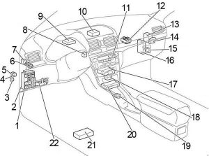
Ford F-550 (2002 – 2007) – fuse box diagram

Ford F-550 (2002 – 2007) – fuse box diagram

Year of production: 2002, 2003, 2004, 2005, 2006, 2007

Passenger Compartment Fuse Box

The fuse panel is located below and to the left of the steering wheel by the brake pedal.

Ford F-250 - fuse box diagram - passenger compartment
Ford F-550 – fuse box diagram – passenger compartment
Number Ampere rating [A] Description
1 15 Adjustable pedals
2 10 ’05-’07: Cluster
3 10 ’05-’07: Upfitter #3
4 20 Power point – instrument panel
5 10 ’05-’07: Upfitter #4
6 20 ’02-’04: Trailer tow turn/stop relay
7 30 High beam headlamps, Flash to pass
8 15 ’03-’04, Diesel: Back-up lamps
20 ’05-’07: Back-up lamps
9 20 ’03-’04: Heated mirrors
10 10 ’02-’04: A/C clutch
11 20 Radio (main)
12 20 Cigar lighter, OBD II
13 5 Power mirrors/switches
14 15 ’02-’04: Daytime running lamps (DRL)
15
16
17 15 Exterior lamps
18 20 Turn lamps (flasher), Brake On-Off (BOO) lamps
19 10 Body security module, 4×4 module
20 10 ’03-’04, Diesel: Fuel Injection Control Module (FICM) relay
15 ’05-’07: Trailer tow Electric Brake Controller (EBC)
21 20 ’05-’07: Heated seats
22 20 Engine control
23 20 Gasoline: Engine control
Diesel: Climate control
24 2 ’03-’04: Brake pressure switch, Speed control
15 ’05-’07: Tow haul, Blower relay, Electronic Automatic Temperature Control
25 10 ’02-’04: 4-Wheel Anti-lock Brake System (4WABS) module, Variable Fan Control (VFC) (’03-’04, Diesel)
26 10 Air bags
27 15 Ignition switch Run feed
28 10 ’02-’04: EATC module, Front blower relay coil
’05-’07: Trailer tow EBC logic
29 10 Customer access
30 15 Highbeam headlamps
31 15 ’02-’04: Clutch interlock switch (manual transmissions only), Transmission range sensor (automatic transmissions only) then to starter relay coil (all transmissions), 4×4
’05: 4×4
’06-’07: Starter relay
32 5 Radio (start)
33 15 ’02-’04: Front wiper
’05-’07: Cluster, 4×4, Wipers
34 10 Brake on-off switch (Low current)
35 10 Instrument cluster
36 10 ’02-’04: PCM Memory
37 15 Horn
38 20 Trailer tow park lamps, backup lamps (’02)
39 15 ’03-’04: Trailer tow back-up lamps
’05-’07: Heated mirrors
40 20 Fuel pump
41 10 Instrument cluster
42 15 Delayed accessory
43 10 Fog lamps
44
45 10 Ignition switch Run/Start feed
46 10 Left-hand low beam
47 10 Right-hand low beam
48
101 30 Trailer tow electric brake
102 30 Door locks/Body security module
103 50 ’02-’04: Ignition switch
30 ’05-’07: Ignition switch
104 40 ’03-’04: Heated backlight
105 30 ’02, Diesel: Injector driver module
’03-’04, Diesel: Fuel heater
106 30 Front wiper main
107 40 ’02-’04: Front blower motor
20 ’05-’07: Trailer tow battery charge
108 30 ’05-’07: Upfitter #1
109 30 ’02-’04: Heated seats
’05-’07: Upfitter #2
110 50 ’02-’04: Ignition switch
30 ’05-’07: Ignition switch
111 30 ’02-’04: 4WD/Shift on the fly
112 30 Left-hand power seats
113 30 Starter motor
114 30 Right-hand power seats
115 20 ’02-’04: Trailer tow battery charge
’05-’07: Upfitter control
116 30 Ignition switch
601 30 Circuit Breaker: Delayed accessory, Power windows, Moonroof
602 60 ’02-’04: 4WABS module
Relay
210
211 ’03-’04, Diesel: Back-up lamps
’05-’07: Back-up lamps
212
301 ’02-’04: Front blower motor
’05-’07: Trailer tow battery charge
302 Powertrain Control Module (PCM)
303 ’02, Diesel: Injector driver module
’03-’04, Diesel: Fuel heater
304 ’03-’04: Heated backlight
305 ’02-’04: Trailer tow battery charge
’05-’07: Upfitter control
306 Delayed accessory
307 Starter

Engine Compartment Fuse Box (’05-’07)

Ford F-250 - fuse box diagram - engine compartment
Ford F-550 – fuse box diagram – engine compartment
Number Ampere rating [A] Description
1 30 Wipers
2 40 Blower
3 30 Electronic Shift on the Fly (ESOF)
4
5 50 Diesel: Injector Driver Module (IDM)
6
7 30 ”05, Diesel: Horizontal Fuel Conditioner Module (HFCM)
8 Shunt
9 20 Trailer tow turn signals
10 10 Powertrain Control Module (PCM) keep alive power, Canister vent solenoid (gasoline)
11 10 Anti-lock Brake System (ABS)
12 2 Brake pressure switch
13 15 Daytime Running Lamps (DRL)
14
15 15 Diesel: Injector Driver Module logic
16
17 10 A/C clutch
18 10 Diesel: Injector Driver Module relay
19
20 10 Trailer tow back-up lamps
21
22 60 ABS (Coils)
23 60 ABS (Pump)
Relay
201 Trailer tow right turn signal/stop lamp
202 Trailer tow left turn signal/stop lamp
203 A/C clutch
204
205 Daytime Running Lamps #1
206 Daytime Running Lamps #2
301 Daytime Running Lamps #3
302
303 Blower
304 Diesel: Injector Driver Module

Auxiliary Relay Box (’06-’07)

An auxiliary relay box is located in the left-hand front side of the engine compartment. This box contains relays for the Electronic Shift On the Fly (ESOF) system.
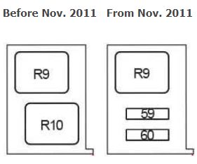
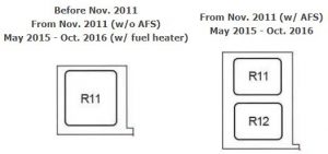
 

WARNING: Terminal and harness assignments for individual connectors will vary depending on vehicle equipment level, model, and market.