Ford F-550 (1992 – 1997) – fuse box diagram

Ford F-550 (1992 – 1997) – fuse box diagram

Year of production: 2000, 2001, 2002, 2003

Passenger Compartment Fuse Box
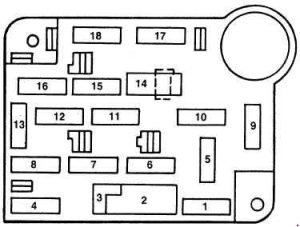
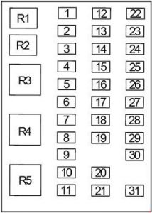
Ford F-250 - fuse box diagram - passenger compartment
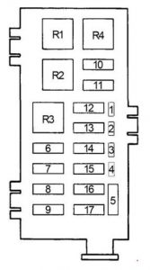
Ford F-550 – fuse box diagram – passenger compartment
Number Ampere rating [A] Description
1 30 ’94-’97: Heater/Air conditioner blower
15 ’92-’93: Stop/hazard lamp, Speed control
2 30 ’94-’97: Wiper/Washer
25 ’92-’93:
Circuit Breaker: Windshield wiper/washer, Internal wiper/washer
3 3 Diesel: Idle position switch
4 15 ’94-’97: Exterior lamps, Instrument illumination, Trailer exterior lamp relay, Warning buzzer/chime module
20 ’92-’93: Turn lamp, License lamps, Anti-theft module, Warning chime, Flash to pass, Trailer running lamp relay, Trailer b/u lamp relay, running lamps, Rear anti-lock brakes (1993)
5 15 ’93: Air bag module, Del module, Aux. battery relay, Starting system, Transmission control switch, Backup lamps, Turn lamps
6 15 ’94-’97: Air conditioner clutch, Diesel auxiliary fuel selector, Remote keyless entry
20 93: Speed control, Remote keyless entry module, Illuminated entry, Accessory tap, Anti-theft module, Trailer batteiy charge relay
7 15 ’94-’97: Turn lamps
30 ’92-’93: Ignition system, Instrument cluster, PLA engine (diesel), EEC relay (1992), TFI module (1992), PCM power relay (1993), Ignition control module (1993)
8 15 ’94-’97: Courtesy/dome/cargo lamps, Electric outside mirrors, Keyless entry, Speedometer, Warning buzzer/chime module
’92-’93: Courtesy lamp switch, Illuminated entry, power mirrors, Visor lamps, Power door lock, Anti-theft indicator, Radio memory, Dome/map lamp, PSOM, Remote convenience module (1992), Remote keyless entry module (1993)
9 25 ’94-’97: Power point
15 ’92-’93: A/C Switch
10 4 ’94-’97: Instrument illumination
15 ’92-’93: Cigar lighter
20 ’92-’93: Cigar lighter, Rear power outlet
11 15 ’94-’97: Radio, Radio display dimmer
’92-’93: Radio and clock, Headlamp switch (1992), Main light switch (1993)
12 20 ’94-’97:
Circuit Breaker: Power door locks, Power driver seat, Power lumbar
’92-’93:
Circuit Breaker: Anti-theft module, Remote convenience module or without A/T power door locks (1992), Remote keyless entry module or without A/T power door locks (1993), Memory lock module
13 15 ’94-’97: Anti-lock brakes, Brake shift interlock, Electronic engine control, Speed control, Stop/hazard lamps, Stop sense for electronic engine control
5 ’92-’93: Instrument panel illumination lamps
14 20 Circuit Breaker: Power windows
15 20 ’94-’97: Anti-lock brakes
15 ’92-’93: Air bag module
16 15 ’94-’97: Cigarette lighter, Generic Scan Tool
30 ’92-’93: Power lumbar, Modified vehicle power
17 10 ’94-’97: Diesel indicators, Electronic transmission, Gauges, Tachometer, Warning buzzer/chime module, Warning indicators
20 ’92-’93: Rear anti-lock brakes, PSOM
18 10 ’94-’97: Brake shift interlock, Speedometer, Selectable RPM control (Diesel), Speed control (Diesel)
15 ’92-’93: Instrument panel warning lamps, Warning chime

Engine Compartment Fuse Box (’92-’93)

Ford F-250 - fuse box diagram - engine compartment (1992 - 1993)
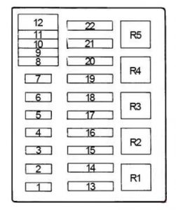
Ford F-550 – fuse box diagram – engine compartment (1992 – 1993)
Number Ampere rating [A] Description
1 15 Horn relay
2 10 Class I trailer running lights, class II trailer running lights relay
3 10 Trailer L/H turn/stop light
4 10 Trailer R/H turn/stop light
5 Diode: Electronic engine control
6 20 Electric brake
7 30 EEC
8 50 Modified vehicle power
9 60 Aux heater-A/C
10 60 Trailer tow, aux battery relay
11 60 Interior fuse panel power feed
12 30 Trailer tow, back-up lights
13 40 Trailer tow
14 30 Fuel pump
15 60 Ignition switch
16 60 Blower motor, cigarette lighter
17 50 Power seats, driver power lumbar
Relay
R1 Horn
R2 Fuel pump
R3 EEC
R4 Blower

Engine Compartment Fuse Box (’94-’97)

Ford F-250 - fuse box diagram - engine compartment
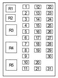
Ford F-550 – fuse box diagram – engine compartment (1994 – 1997)
Number Ampere rating [A] Description
1 20 Audio power
2 15 200 Amp alternator (Diesel ambulance only)
3 30 Daytime running lamps (Canada only), Headlamp flash-to-pass, Horn
4 25 Trailer back-up lamps, Trailer running lamps
5 15 Back-up lamps, Daytime running lamp module (DRL) (Canada only), Oxygen sensor heater, Trailer battery charge relay
6 10 Trailer right-hand stop/turn lamp
7 10 Trailer left-hand stop/turn lamp
8 30 Injector driver module (Diesel)
9 30 Gasoline: Powertrain control system
20 Diesel: Powertrain control system
10 20 Instrument panel fuses: 15,18, Starter relay coil
11
12 Diode: Powertrain control system relay coil
13 50 Instrument panel fuses: 5,9,13
14
15 50 Instrument panel fuses: 1, 7, Power distribution box: fuse 5
16 20 Gasoline: Fuel pump feed
17 50 Alternator charge lamp, Idle position switch (Diesel), Instrument panel fuses: 2,6, 11,14,17, Power distribution box: fuse 22
18 30 Trailer battery charge
19 40 Headlamps
20 50 Instrument panel fuses: 4, 8, 12,16
21 30 Trailer brake feed
22 20 Gasoline: Distributor pickup, Ignition coil, Powertrain control system relay coil, Thick film integrated (TFI) module
30 Diesel: Fuel line heater, Glow plug controller, Powertrain control system relay coil
Relay
R1 Powertrain control system
R2 Gasoline: Fuel pump
Diesel: Injector driver module (IDM relay)
R3 Horn
R4 Trailer tow lamps
R5

Additional Fuses

Fuse Ampere rating [A] Location
Headlamps & High Beam Indicator 22 Circuit Breaker: Integral with Headlamp Switch
Gasoline: Alternator, 95 12 Fuse Links: At Starting Motor Relay
Fuse Links: At Starting Motor Relay 12(2) Fuse Links: At Starting Motor Relay
Diesel Glow Plugs 14(2) Fuse Links: At Starting Motor Relay

WARNING: Terminal and harness assignments for individual connectors will vary depending on vehicle equipment level, model, and market.

Ford F-450 (1992 – 1997) – fuse box diagram

Ford F-450 (1992 – 1997) – fuse box diagram

Year of production: 2000, 2001, 2002, 2003

Passenger Compartment Fuse Box

Ford F-250 - fuse box diagram - passenger compartment
Ford F-450 – fuse box diagram – passenger compartment
Number Ampere rating [A] Description
1 30 ’94-’97: Heater/Air conditioner blower
15 ’92-’93: Stop/hazard lamp, Speed control
2 30 ’94-’97: Wiper/Washer
25 ’92-’93:
Circuit Breaker: Windshield wiper/washer, Internal wiper/washer
3 3 Diesel: Idle position switch
4 15 ’94-’97: Exterior lamps, Instrument illumination, Trailer exterior lamp relay, Warning buzzer/chime module
20 ’92-’93: Turn lamp, License lamps, Anti-theft module, Warning chime, Flash to pass, Trailer running lamp relay, Trailer b/u lamp relay, running lamps, Rear anti-lock brakes (1993)
5 15 ’93: Air bag module, Del module, Aux. battery relay, Starting system, Transmission control switch, Backup lamps, Turn lamps
6 15 ’94-’97: Air conditioner clutch, Diesel auxiliary fuel selector, Remote keyless entry
20 93: Speed control, Remote keyless entry module, Illuminated entry, Accessory tap, Anti-theft module, Trailer batteiy charge relay
7 15 ’94-’97: Turn lamps
30 ’92-’93: Ignition system, Instrument cluster, PLA engine (diesel), EEC relay (1992), TFI module (1992), PCM power relay (1993), Ignition control module (1993)
8 15 ’94-’97: Courtesy/dome/cargo lamps, Electric outside mirrors, Keyless entry, Speedometer, Warning buzzer/chime module
’92-’93: Courtesy lamp switch, Illuminated entry, power mirrors, Visor lamps, Power door lock, Anti-theft indicator, Radio memory, Dome/map lamp, PSOM, Remote convenience module (1992), Remote keyless entry module (1993)
9 25 ’94-’97: Power point
15 ’92-’93: A/C Switch
10 4 ’94-’97: Instrument illumination
15 ’92-’93: Cigar lighter
20 ’92-’93: Cigar lighter, Rear power outlet
11 15 ’94-’97: Radio, Radio display dimmer
’92-’93: Radio and clock, Headlamp switch (1992), Main light switch (1993)
12 20 ’94-’97:
Circuit Breaker: Power door locks, Power driver seat, Power lumbar
’92-’93:
Circuit Breaker: Anti-theft module, Remote convenience module or without A/T power door locks (1992), Remote keyless entry module or without A/T power door locks (1993), Memory lock module
13 15 ’94-’97: Anti-lock brakes, Brake shift interlock, Electronic engine control, Speed control, Stop/hazard lamps, Stop sense for electronic engine control
5 ’92-’93: Instrument panel illumination lamps
14 20 Circuit Breaker: Power windows
15 20 ’94-’97: Anti-lock brakes
15 ’92-’93: Air bag module
16 15 ’94-’97: Cigarette lighter, Generic Scan Tool
30 ’92-’93: Power lumbar, Modified vehicle power
17 10 ’94-’97: Diesel indicators, Electronic transmission, Gauges, Tachometer, Warning buzzer/chime module, Warning indicators
20 ’92-’93: Rear anti-lock brakes, PSOM
18 10 ’94-’97: Brake shift interlock, Speedometer, Selectable RPM control (Diesel), Speed control (Diesel)
15 ’92-’93: Instrument panel warning lamps, Warning chime

Engine Compartment Fuse Box (’92-’93)

Ford F-250 - fuse box diagram - engine compartment (1992 - 1993)
Ford F-450 – fuse box diagram – engine compartment (1992 – 1993)
Number Ampere rating [A] Description
1 15 Horn relay
2 10 Class I trailer running lights, class II trailer running lights relay
3 10 Trailer L/H turn/stop light
4 10 Trailer R/H turn/stop light
5 Diode: Electronic engine control
6 20 Electric brake
7 30 EEC
8 50 Modified vehicle power
9 60 Aux heater-A/C
10 60 Trailer tow, aux battery relay
11 60 Interior fuse panel power feed
12 30 Trailer tow, back-up lights
13 40 Trailer tow
14 30 Fuel pump
15 60 Ignition switch
16 60 Blower motor, cigarette lighter
17 50 Power seats, driver power lumbar
Relay
R1 Horn
R2 Fuel pump
R3 EEC
R4 Blower

Engine Compartment Fuse Box (’94-’97)

Ford F-250 - fuse box diagram - engine compartment
Ford F-450 – fuse box diagram – engine compartment (1994 – 1997)
Number Ampere rating [A] Description
1 20 Audio power
2 15 200 Amp alternator (Diesel ambulance only)
3 30 Daytime running lamps (Canada only), Headlamp flash-to-pass, Horn
4 25 Trailer back-up lamps, Trailer running lamps
5 15 Back-up lamps, Daytime running lamp module (DRL) (Canada only), Oxygen sensor heater, Trailer battery charge relay
6 10 Trailer right-hand stop/turn lamp
7 10 Trailer left-hand stop/turn lamp
8 30 Injector driver module (Diesel)
9 30 Gasoline: Powertrain control system
20 Diesel: Powertrain control system
10 20 Instrument panel fuses: 15,18, Starter relay coil
11
12 Diode: Powertrain control system relay coil
13 50 Instrument panel fuses: 5,9,13
14
15 50 Instrument panel fuses: 1, 7, Power distribution box: fuse 5
16 20 Gasoline: Fuel pump feed
17 50 Alternator charge lamp, Idle position switch (Diesel), Instrument panel fuses: 2,6, 11,14,17, Power distribution box: fuse 22
18 30 Trailer battery charge
19 40 Headlamps
20 50 Instrument panel fuses: 4, 8, 12,16
21 30 Trailer brake feed
22 20 Gasoline: Distributor pickup, Ignition coil, Powertrain control system relay coil, Thick film integrated (TFI) module
30 Diesel: Fuel line heater, Glow plug controller, Powertrain control system relay coil
Relay
R1 Powertrain control system
R2 Gasoline: Fuel pump
Diesel: Injector driver module (IDM relay)
R3 Horn
R4 Trailer tow lamps
R5

Additional Fuses

Fuse Ampere rating [A] Location
Headlamps & High Beam Indicator 22 Circuit Breaker: Integral with Headlamp Switch
Gasoline: Alternator, 95 12 Fuse Links: At Starting Motor Relay
Fuse Links: At Starting Motor Relay 12(2) Fuse Links: At Starting Motor Relay
Diesel Glow Plugs 14(2) Fuse Links: At Starting Motor Relay

WARNING: Terminal and harness assignments for individual connectors will vary depending on vehicle equipment level, model, and market.
Ford F-350 (1992 – 1997) – fuse box diagram

Ford F-350 (1992 – 1997) – fuse box diagram

Year of production: 2000, 2001, 2002, 2003

Passenger Compartment Fuse Box

Ford F-250 - fuse box diagram - passenger compartment
Ford F-350 – fuse box diagram – passenger compartment
Number Ampere rating [A] Description
1 30 ’94-’97: Heater/Air conditioner blower
15 ’92-’93: Stop/hazard lamp, Speed control
2 30 ’94-’97: Wiper/Washer
25 ’92-’93:
Circuit Breaker: Windshield wiper/washer, Internal wiper/washer
3 3 Diesel: Idle position switch
4 15 ’94-’97: Exterior lamps, Instrument illumination, Trailer exterior lamp relay, Warning buzzer/chime module
20 ’92-’93: Turn lamp, License lamps, Anti-theft module, Warning chime, Flash to pass, Trailer running lamp relay, Trailer b/u lamp relay, running lamps, Rear anti-lock brakes (1993)
5 15 ’93: Air bag module, Del module, Aux. battery relay, Starting system, Transmission control switch, Backup lamps, Turn lamps
6 15 ’94-’97: Air conditioner clutch, Diesel auxiliary fuel selector, Remote keyless entry
20 93: Speed control, Remote keyless entry module, Illuminated entry, Accessory tap, Anti-theft module, Trailer batteiy charge relay
7 15 ’94-’97: Turn lamps
30 ’92-’93: Ignition system, Instrument cluster, PLA engine (diesel), EEC relay (1992), TFI module (1992), PCM power relay (1993), Ignition control module (1993)
8 15 ’94-’97: Courtesy/dome/cargo lamps, Electric outside mirrors, Keyless entry, Speedometer, Warning buzzer/chime module
’92-’93: Courtesy lamp switch, Illuminated entry, power mirrors, Visor lamps, Power door lock, Anti-theft indicator, Radio memory, Dome/map lamp, PSOM, Remote convenience module (1992), Remote keyless entry module (1993)
9 25 ’94-’97: Power point
15 ’92-’93: A/C Switch
10 4 ’94-’97: Instrument illumination
15 ’92-’93: Cigar lighter
20 ’92-’93: Cigar lighter, Rear power outlet
11 15 ’94-’97: Radio, Radio display dimmer
’92-’93: Radio and clock, Headlamp switch (1992), Main light switch (1993)
12 20 ’94-’97:
Circuit Breaker: Power door locks, Power driver seat, Power lumbar
’92-’93:
Circuit Breaker: Anti-theft module, Remote convenience module or without A/T power door locks (1992), Remote keyless entry module or without A/T power door locks (1993), Memory lock module
13 15 ’94-’97: Anti-lock brakes, Brake shift interlock, Electronic engine control, Speed control, Stop/hazard lamps, Stop sense for electronic engine control
5 ’92-’93: Instrument panel illumination lamps
14 20 Circuit Breaker: Power windows
15 20 ’94-’97: Anti-lock brakes
15 ’92-’93: Air bag module
16 15 ’94-’97: Cigarette lighter, Generic Scan Tool
30 ’92-’93: Power lumbar, Modified vehicle power
17 10 ’94-’97: Diesel indicators, Electronic transmission, Gauges, Tachometer, Warning buzzer/chime module, Warning indicators
20 ’92-’93: Rear anti-lock brakes, PSOM
18 10 ’94-’97: Brake shift interlock, Speedometer, Selectable RPM control (Diesel), Speed control (Diesel)
15 ’92-’93: Instrument panel warning lamps, Warning chime

Engine Compartment Fuse Box (’92-’93)

Ford F-250 - fuse box diagram - engine compartment (1992 - 1993)
Ford F-350 – fuse box diagram – engine compartment (1992 – 1993)
Number Ampere rating [A] Description
1 15 Horn relay
2 10 Class I trailer running lights, class II trailer running lights relay
3 10 Trailer L/H turn/stop light
4 10 Trailer R/H turn/stop light
5 Diode: Electronic engine control
6 20 Electric brake
7 30 EEC
8 50 Modified vehicle power
9 60 Aux heater-A/C
10 60 Trailer tow, aux battery relay
11 60 Interior fuse panel power feed
12 30 Trailer tow, back-up lights
13 40 Trailer tow
14 30 Fuel pump
15 60 Ignition switch
16 60 Blower motor, cigarette lighter
17 50 Power seats, driver power lumbar
Relay
R1 Horn
R2 Fuel pump
R3 EEC
R4 Blower

Engine Compartment Fuse Box (’94-’97)

Ford F-250 - fuse box diagram - engine compartment
Ford F-350 – fuse box diagram – engine compartment (1994 – 1997)
Number Ampere rating [A] Description
1 20 Audio power
2 15 200 Amp alternator (Diesel ambulance only)
3 30 Daytime running lamps (Canada only), Headlamp flash-to-pass, Horn
4 25 Trailer back-up lamps, Trailer running lamps
5 15 Back-up lamps, Daytime running lamp module (DRL) (Canada only), Oxygen sensor heater, Trailer battery charge relay
6 10 Trailer right-hand stop/turn lamp
7 10 Trailer left-hand stop/turn lamp
8 30 Injector driver module (Diesel)
9 30 Gasoline: Powertrain control system
20 Diesel: Powertrain control system
10 20 Instrument panel fuses: 15,18, Starter relay coil
11
12 Diode: Powertrain control system relay coil
13 50 Instrument panel fuses: 5,9,13
14
15 50 Instrument panel fuses: 1, 7, Power distribution box: fuse 5
16 20 Gasoline: Fuel pump feed
17 50 Alternator charge lamp, Idle position switch (Diesel), Instrument panel fuses: 2,6, 11,14,17, Power distribution box: fuse 22
18 30 Trailer battery charge
19 40 Headlamps
20 50 Instrument panel fuses: 4, 8, 12,16
21 30 Trailer brake feed
22 20 Gasoline: Distributor pickup, Ignition coil, Powertrain control system relay coil, Thick film integrated (TFI) module
30 Diesel: Fuel line heater, Glow plug controller, Powertrain control system relay coil
Relay
R1 Powertrain control system
R2 Gasoline: Fuel pump
Diesel: Injector driver module (IDM relay)
R3 Horn
R4 Trailer tow lamps
R5

Additional Fuses

Fuse Ampere rating [A] Location
Headlamps & High Beam Indicator 22 Circuit Breaker: Integral with Headlamp Switch
Gasoline: Alternator, 95 12 Fuse Links: At Starting Motor Relay
Fuse Links: At Starting Motor Relay 12(2) Fuse Links: At Starting Motor Relay
Diesel Glow Plugs 14(2) Fuse Links: At Starting Motor Relay

WARNING: Terminal and harness assignments for individual connectors will vary depending on vehicle equipment level, model, and market.

Ford F-250 (1992 – 1997) – fuse box diagram

Ford F-250 (1992 – 1997) – fuse box diagram

Year of production: 2000, 2001, 2002, 2003

Passenger Compartment Fuse Box

Ford F-250 - fuse box diagram - passenger compartment
Ford F-250 – fuse box diagram – passenger compartment
Number Ampere rating [A] Description
1 30 ’94-’97: Heater/Air conditioner blower
15 ’92-’93: Stop/hazard lamp, Speed control
2 30 ’94-’97: Wiper/Washer
25 ’92-’93:
Circuit Breaker: Windshield wiper/washer, Internal wiper/washer
3 3 Diesel: Idle position switch
4 15 ’94-’97: Exterior lamps, Instrument illumination, Trailer exterior lamp relay, Warning buzzer/chime module
20 ’92-’93: Turn lamp, License lamps, Anti-theft module, Warning chime, Flash to pass, Trailer running lamp relay, Trailer b/u lamp relay, running lamps, Rear anti-lock brakes (1993)
5 15 ’93: Air bag module, Del module, Aux. battery relay, Starting system, Transmission control switch, Backup lamps, Turn lamps
6 15 ’94-’97: Air conditioner clutch, Diesel auxiliary fuel selector, Remote keyless entry
20 93: Speed control, Remote keyless entry module, Illuminated entry, Accessory tap, Anti-theft module, Trailer batteiy charge relay
7 15 ’94-’97: Turn lamps
30 ’92-’93: Ignition system, Instrument cluster, PLA engine (diesel), EEC relay (1992), TFI module (1992), PCM power relay (1993), Ignition control module (1993)
8 15 ’94-’97: Courtesy/dome/cargo lamps, Electric outside mirrors, Keyless entry, Speedometer, Warning buzzer/chime module
’92-’93: Courtesy lamp switch, Illuminated entry, power mirrors, Visor lamps, Power door lock, Anti-theft indicator, Radio memory, Dome/map lamp, PSOM, Remote convenience module (1992), Remote keyless entry module (1993)
9 25 ’94-’97: Power point
15 ’92-’93: A/C Switch
10 4 ’94-’97: Instrument illumination
15 ’92-’93: Cigar lighter
20 ’92-’93: Cigar lighter, Rear power outlet
11 15 ’94-’97: Radio, Radio display dimmer
’92-’93: Radio and clock, Headlamp switch (1992), Main light switch (1993)
12 20 ’94-’97:
Circuit Breaker: Power door locks, Power driver seat, Power lumbar
’92-’93:
Circuit Breaker: Anti-theft module, Remote convenience module or without A/T power door locks (1992), Remote keyless entry module or without A/T power door locks (1993), Memory lock module
13 15 ’94-’97: Anti-lock brakes, Brake shift interlock, Electronic engine control, Speed control, Stop/hazard lamps, Stop sense for electronic engine control
5 ’92-’93: Instrument panel illumination lamps
14 20 Circuit Breaker: Power windows
15 20 ’94-’97: Anti-lock brakes
15 ’92-’93: Air bag module
16 15 ’94-’97: Cigarette lighter, Generic Scan Tool
30 ’92-’93: Power lumbar, Modified vehicle power
17 10 ’94-’97: Diesel indicators, Electronic transmission, Gauges, Tachometer, Warning buzzer/chime module, Warning indicators
20 ’92-’93: Rear anti-lock brakes, PSOM
18 10 ’94-’97: Brake shift interlock, Speedometer, Selectable RPM control (Diesel), Speed control (Diesel)
15 ’92-’93: Instrument panel warning lamps, Warning chime

Engine Compartment Fuse Box (’92-’93)

Ford F-250 - fuse box diagram - engine compartment (1992 - 1993)
Ford F-250 – fuse box diagram – engine compartment (1992 – 1993)
Number Ampere rating [A] Description
1 15 Horn relay
2 10 Class I trailer running lights, class II trailer running lights relay
3 10 Trailer L/H turn/stop light
4 10 Trailer R/H turn/stop light
5 Diode: Electronic engine control
6 20 Electric brake
7 30 EEC
8 50 Modified vehicle power
9 60 Aux heater-A/C
10 60 Trailer tow, aux battery relay
11 60 Interior fuse panel power feed
12 30 Trailer tow, back-up lights
13 40 Trailer tow
14 30 Fuel pump
15 60 Ignition switch
16 60 Blower motor, cigarette lighter
17 50 Power seats, driver power lumbar
Relay
R1 Horn
R2 Fuel pump
R3 EEC
R4 Blower

Engine Compartment Fuse Box (’94-’97)

Ford F-250 - fuse box diagram - engine compartment
Ford F-250 – fuse box diagram – engine compartment (1994 – 1997)
Number Ampere rating [A] Description
1 20 Audio power
2 15 200 Amp alternator (Diesel ambulance only)
3 30 Daytime running lamps (Canada only), Headlamp flash-to-pass, Horn
4 25 Trailer back-up lamps, Trailer running lamps
5 15 Back-up lamps, Daytime running lamp module (DRL) (Canada only), Oxygen sensor heater, Trailer battery charge relay
6 10 Trailer right-hand stop/turn lamp
7 10 Trailer left-hand stop/turn lamp
8 30 Injector driver module (Diesel)
9 30 Gasoline: Powertrain control system
20 Diesel: Powertrain control system
10 20 Instrument panel fuses: 15,18, Starter relay coil
11
12 Diode: Powertrain control system relay coil
13 50 Instrument panel fuses: 5,9,13
14
15 50 Instrument panel fuses: 1, 7, Power distribution box: fuse 5
16 20 Gasoline: Fuel pump feed
17 50 Alternator charge lamp, Idle position switch (Diesel), Instrument panel fuses: 2,6, 11,14,17, Power distribution box: fuse 22
18 30 Trailer battery charge
19 40 Headlamps
20 50 Instrument panel fuses: 4, 8, 12,16
21 30 Trailer brake feed
22 20 Gasoline: Distributor pickup, Ignition coil, Powertrain control system relay coil, Thick film integrated (TFI) module
30 Diesel: Fuel line heater, Glow plug controller, Powertrain control system relay coil
Relay
R1 Powertrain control system
R2 Gasoline: Fuel pump
Diesel: Injector driver module (IDM relay)
R3 Horn
R4 Trailer tow lamps
R5

Additional Fuses

Fuse Ampere rating [A] Location
Headlamps & High Beam Indicator 22 Circuit Breaker: Integral with Headlamp Switch
Gasoline: Alternator, 95 12 Fuse Links: At Starting Motor Relay
Fuse Links: At Starting Motor Relay 12(2) Fuse Links: At Starting Motor Relay
Diesel Glow Plugs 14(2) Fuse Links: At Starting Motor Relay

WARNING: Terminal and harness assignments for individual connectors will vary depending on vehicle equipment level, model, and market.
Mercury Mariner (2008 – 2011) – fuse box diagram

Mercury Mariner (2008 – 2011) – fuse box diagram

Year of production: 2005, 2006, 2007

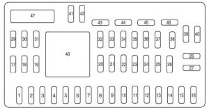
Passenger compartment fuse panel

The fuse panel is located on the right-hand side of the center console, by the instrument panel.

Mercury Mariner - fuse box diagram - passenger compartment
Mercury Mariner – fuse box diagram – passenger compartment
Fuse/relay Ampere rating [A] Description
1 30 110V inverter
2 15 Brake On/Off switch
3 15 ’09-’11: SYNC module
4 30 ’09-’11: Moon roof
5 10 Keypad illumination, Brake Shift Interlock (BSI), Passenger compartment fuse panel
6 20 Turn signals, Stop lamps
7 10 Low beam headlamps (left)
8 10 Low beam headlamps (right)
9 15 Interior lights
10 15 Backlighting
11 10 Four wheel drive
12 7,5 Power mirror switch
13 7,5 ’08: Canister vent
14 10 FCIM (radio buttons), Satellite radio, Front display module, GPS module (’10-’11)
15 10 Climate control
16 15
17 20 All lock motor feeds, Liftgate release, Liftglass release
18 20 Heated seat
19 25 Rear wiper
20 15 Datalink
21 15 Fog lamps
22 15 Park lamps
23 15 High beam headlamps
24 20 Horn relay
25 10 Demand lamps
26 10 Instrument panel cluster
27 20 Ignition switch
28 5 Radio
29 5 Instrument panel cluster
30 5 ’08: Overdrive cancel
31 10 Restraints control module
32 10 ’10-’11: Rear video camera module
33 10 ’08: Speed control switch
34 5 ’08: Speed control deactivate switch, ABS
35 10 Four wheel drive, Electric power assist steering (EPAS), Park aid module, Active park assist module (’10-’11), 110V inverter module
36 5 Passive anti-theft system (PATS) transceiver
37 10 Climate control
38 20 Subwoofer/Amp (audiophile radio / premium radio)
39 20 Radio, Radio amplifier (navigation only (’10-’11))
40 20 Front power point
41 15 Driver/passenger door lock switches, Automatic dimming mirror, Compass, Ambient lighting, Moon roof, Camera display in mirror
42 10
43 10 Rear wiper logic, Heated seats relay, Instrument cluster
44 10
45 5 Front wiper logic, Blower motor relay
46 7,5 Occupant classification system (OCS), Passenger airbag deactivation indicator (PADI)
47 30 Circuit Breaker: Power windows, Moon roof (’08)
Relay
48 Delayed accessory

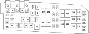
Engine Compartment Fuse Box

2008, Hybrid

Mercury Mariner - fuse box diagram - engine compartment - hybrid (2008)
Mercury Mariner – fuse box diagram – engine compartment – hybrid (2008)

2009-2011

Mercury Mariner - fuse box diagram - engine compartment (2009 - 2011)
Mercury Mariner – fuse box diagram – engine compartment (2009 – 2011)
Fuse/relay Ampere rating [A] Description
A 80 Electronic power steering module (EPAS)
B 125 Passenger compartment fuse panel (SPDJB)
1 15 Heated mirror
2 30 Rear defroster
3 20 Rear power point (center console)
4 20 ’08: Fuel pump (except Hybrid)
40 Hybrid: Electric vacuum pump
5 10 Powertrain Control Module (PCM) Keep Alive power, PCM relay (’09-’11), Canister vent (’09-’11), Transmission control module (Hybrid)
6 15 except Hybrid: Alternator
7 10 ’08: Reverse lamps
15 ’09-’11: Liftgate latch
8 20 Trailer tow parking lamps
5 Hybrid: Traction battery control module
9 50 Anti-lock Brake System (ABS)
Hybrid: Brake control module
10 30 Front wipers
11 30 except Hybrid: Starter
12 40 Blower motor
13 10 A/C clutch
14 15 except Hybrid: Trailer tow turn lamps
10 Hybrid: Heater/Coolant pump
15 10 Hybrid: Traction Battery Control Module (TBCM)
16 40 Cooling fan 1
17 40 Cooling fan 2
18 20 except Hybrid: ABS solenoid
50 Hybrid: Brake control module solenoid
19 30 Power seats
22 20 ’09-’11: Fuel pump (except Hybrid)
15 Hybrid: Ignition coils
23 15 ’09-’11: Fuel injectors (except Hybrid)
24 10 ’08: PCM transmission (except Hybrid)
Hybrid: Transmission control module
25 5 ’09-’11: Anti-lock Brake System (ABS) (except Hybrid)
Hybrid: Traction battery control module, Thermal expansion valve
26 10 ’08: PCM mil (except Hybrid)
15 ’09-’11: Ignition coils (except Hybrid)
20 Hybrid: Fuel pump, Traction battery control module
27 10 ’08: PCM non-mil
’09-’11: PCM – general powertrain components malfunction indicator lamp
28 15 ’08: PCM (except Hybrid)
Hybrid: Heated Exhaust Gas Oxygen (HEGO) sensor, PCM (mil-on — malfunction indicator lamp)
20 ’09-’11: PCM – emission related powertrain components malfunction indicator lamp (except Hybrid)
29 15 ’08: Ignition coils
’09-’11: PCM
32 Hybrid: A/C clutch diode
33 PCM diode
34 except Hybrid: Start diode
35 10 Reverse lamp relay, Speed control module (’08), Rear defrost relay, Run/start (’09-’11)
36
37
Relay
20 A/C clutch
21A Rear defroster
21B ’09-’11: Fuel pump
Hybrid: Ignition
21C Blower
21D PCM
30 Cooling fan 1
30B Starter
Hybrid: Electric vacuum pump mechanical
30C Cooling fan main
30D Cooling fan 2
31A Reverse lamp
31B ’08: Fuel pump
31C except Hybrid: Trailer tow left turn
Hybrid: Heater pump
31D except Hybrid: Trailer tow right turn
Hybrid: 
Coolant pump
31E except Hybrid: Trailer tow park
31F 09-’11: Liftgate latch

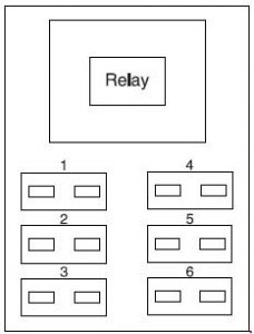
Auxiliary relay box (Hybrid)

Mercury Mariner - fuse box diagram - auxilliary relay box (hybrid)
Mercury Mariner – fuse box diagram – auxilliary relay box (hybrid)
Fuse/relay Ampere rating [A] Description
1
2
3
4 5 Vacuum pump monitor
5
6
Relay
R1 Electric vacuum pump (solid state)

WARNING: Terminal and harness assignments for individual connectors will vary depending on vehicle equipment level, model, and market

Ford F-650 (2000 – 2003) – fuse box diagram

Ford F-650 (2000 – 2003) – fuse box diagram

Year of production: 2000, 2001, 2002, 2003

Passenger Compartment Fuse Box

Ford F-650 - fuse box diagram - passenger compartment
Ford F-650 – fuse box diagram – passenger compartment
Number Ampere rating [A] Description
1 20 Horn
2 15 Turn/Hazard Lamps
3 20 Cigar lighter
4 10 Diagnostic Connectors
5 15 Back-Up Lamps, Daytime Running Lamps (DRL) Relays, Blend Door Actuator Heated Seat Module (SuperCrewzer only), On/Off Fan Clutch (SuperCrewzer only), Warning Chime Module (SuperCrewzer and Ambulance)
6
7
8 5 Radio, GEM
9 5 Switch Illumination (Headlamp, Power Windows, Power Door Locks), Power Window Relay, Trailer Hook Up Lamps (SuperCrewzer only)
10
11 30 Wiper Motor, Washer Pump Relay
12 10 Hydraulic Brake: Stoplamp Switch
13 20 Radio, Cluster, Powertrain Control Module (PCM (7.3L Power Stroke)), Keep Alive Memory
14 10 Interior Lamps, Runningboard lamps (SuperCrewzer only)
15 10 GEM, Interior Lamp Relay, GEM, Map Lamps, Glove Box Lamps (SuperCrewzer only), Power Mirrors (SuperCrewzer only), Warning Chime Module (SuperCrewzer only)
16 15 Highbeams
17
18 5 Headlamp switch, GEM
19 15 Engine, Cluster, Powertrain Control Module (PCM), Alternator (Ambulance only)
20 15 Starter Relay, GEM
21 10 Daytime Running Lamps (DRL)
22 15 Super CrewZer: Exhaust Brake, Heated Mirrors, Rear Air Suspension
23 10 Electronic Flasher
24 15 Vacuum Pump, Air Dryer, ABS, Fuel Heater Relay
25 10 Blower Motor Relay
26 10 Right Low Beam Headlamp
27
28 10 Left Low Beam Headlamp
29 10 Cluster, GEM, Powertrain Control Module (clutch switch input (7.3L Power Stroke only) ), APCM (7.3L Power Stroke only), Overhead Console (SuperCrewzer only), Keyless Entry Module (SuperCrewzer only), Traxx (Fuel) Module (SuperCrewzer only)
30 30 Power Stroke 7.3L: Powertrain Control Module (PCM) Diode, Fuel Heater
31 15 Allison MD Transmission, Neutral Start Relay and PCM (7.3L Power Stroke only)
Relay
R1 Interior lamp relay
R2
R3 Horn relay
R4 One Touch Down
R5

Engine Compartment Fuse Box

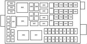
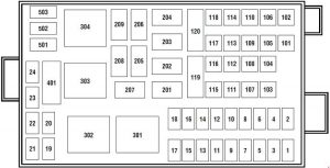
Ford F-650 - fuse box diagram - engine compartment
Ford F-650 – fuse box diagram – engine compartment
Number Ampere rating [A] Description
1 15 Park Lamps, Roof Lamps
2 25 Cummins: Powertrain Control Module (PCM)
15 Super CrewZer: Foglamps
3 30 Generator
4 15 Washer Pump
5 15 Caterpillar: Air Intake Heater Relay
Cummins: Powertrain Control Module (PCM)
6 20 Powertrain Control Module (PCM)
7 15 Stop Lamps
8 25 Caterpillar: Fuel Heater
9 30 Super CrewZer: Trailer Hook Up lamps
10 15 Allison AT: Shift Modulator
11 20 Allison MD Transmission, Allison 2000/2400 Transmission
12 10 Super CrewZer: Keyless Entry Module
13 10 Super CrewZer: Park Brake Adjustment Module
14
15 7,5 Hydraulic Brake: Body Builder Prep
16 10 ’01-’03: Allison 2000/2400 Transmission
17 5 Super CrewZer: Radio
18
19
20
21 10 Hydraulic Brake: GEM
22
23
24
101 40 Air Brake: Anti-lock Brake System (ABS)
102 20 Body Builder Prep Run Feed
103 50 Ignition Switch (JB fuses 8, 9, 11, 19, 20, 22, 23, 24, 25, 29, 30, 31)
104 20 Power point
105 20 Door lock switches
106 30 Headlamps
107 50 Junction Box Battery Feed (fuses 1, 2, 3, 4, 12, 13, 14, 15)
108 40 Cummins Fuel Heater
109 40 Power Windows
110 30 Super CrewZer: Power Seats
111 30 Body Builder Prep
112 40 Blower Motor
113 30 Super CrewZer: Heated Seats
114 30 Super CrewZer: E-Brake
115 40 Ignition Switch (JB fuses 5, 8, 9, 11, 21)
116 30 Body Builder Prep
117 20 Power Stroke 7.3L: Powertrain Control Module (PCM)
118 30 Power Stroke 7.3L: IDM
119 60 Hydraulic ABS, Air Brake Trailer Tow Fuse Block (’01-’03)
120 60 Hydromax Motor, Air Brake Trailer Tow Fuse Block (’01-’03)
Relay
201 Washer pump relay
202 Wiper speed relay
203 Wiper run-park relay
204 Cummins (’00): Cummins VP44 Relay
Power Stroke 7.3L: Neutral Start Relay
Caterpillar (’01-’03) / Cummins (’01-’03): Stoplamp Relay
205 Right Hand Stop/Turn Relay
206 Left Hand Stop/Turn Relay
207 Caterpillar / Power Stroke: Shift Modulator Relay
Cummins (’01-’03): Cummins VP44 Relay
Super CrewZer: A/C High Pressure Relay
208 Backup Lamps Relay
209 Stop Lamps Relay
Super CrewZer: Foglamps Relay
301 Caterpillar / Cummins: Fuel Heater Relay
Power Stroke 7.3L: Powertrain Control Module (PCM) Relay
302 Park Lamps Relay
303 Blower Motor Relay
304 Air ABS Relay
401
Diode
501
502
503 Power Stroke 7.3L: Powertrain Control Module (PCM) Diode

Additional Relay Box No.2

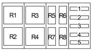
Ford-F-650 - fuse box diagram - additional relay box 2
Ford-F-650 – fuse box diagram – additional relay box 2
Number Ampere rating [A] Description
1 30 Trailer tow ABS feed
2 30 Trailer tow park/marker lamps
3 30 Trailer tow stop lamps
4 30 Trailer Tow Turn/Stop Lamps
5
Relay
R1 Trailer Tow Run Relay
Super CrewZer: Trailer Hookup Lamps Relay
R2 Trailer Tow Stop Lamp relay
Super CrewZer: Exhaust Brake Relay
R3 Trailer Tow Park/Marker Lamp Relay
Super CrewZer: Exhaust Brake Relay
R4 Trailer Tow Park/Marker Lamp Relay
R5
R6
R7 ‘Trailer Tow Left Turn/Stop Lamp Relay
R8 Trailer Tow Right Turn/Stop Lamp Relay

WARNING: Terminal and harness assignments for individual connectors will vary depending on vehicle equipment level, model, and market.
Ford F-750 (2000 – 2003) – fuse box diagram

Ford F-750 (2000 – 2003) – fuse box diagram

Year of production: 2000, 2001, 2002, 2003

Passenger Compartment Fuse Box

Ford F-650 - fuse box diagram - passenger compartment
Ford F-750 – fuse box diagram – passenger compartment
Number Ampere rating [A] Description
1 20 Horn
2 15 Turn/Hazard Lamps
3 20 Cigar lighter
4 10 Diagnostic Connectors
5 15 Back-Up Lamps, Daytime Running Lamps (DRL) Relays, Blend Door Actuator Heated Seat Module (SuperCrewzer only), On/Off Fan Clutch (SuperCrewzer only), Warning Chime Module (SuperCrewzer and Ambulance)
6
7
8 5 Radio, GEM
9 5 Switch Illumination (Headlamp, Power Windows, Power Door Locks), Power Window Relay, Trailer Hook Up Lamps (SuperCrewzer only)
10
11 30 Wiper Motor, Washer Pump Relay
12 10 Hydraulic Brake: Stoplamp Switch
13 20 Radio, Cluster, Powertrain Control Module (PCM (7.3L Power Stroke)), Keep Alive Memory
14 10 Interior Lamps, Runningboard lamps (SuperCrewzer only)
15 10 GEM, Interior Lamp Relay, GEM, Map Lamps, Glove Box Lamps (SuperCrewzer only), Power Mirrors (SuperCrewzer only), Warning Chime Module (SuperCrewzer only)
16 15 Highbeams
17
18 5 Headlamp switch, GEM
19 15 Engine, Cluster, Powertrain Control Module (PCM), Alternator (Ambulance only)
20 15 Starter Relay, GEM
21 10 Daytime Running Lamps (DRL)
22 15 Super CrewZer: Exhaust Brake, Heated Mirrors, Rear Air Suspension
23 10 Electronic Flasher
24 15 Vacuum Pump, Air Dryer, ABS, Fuel Heater Relay
25 10 Blower Motor Relay
26 10 Right Low Beam Headlamp
27
28 10 Left Low Beam Headlamp
29 10 Cluster, GEM, Powertrain Control Module (clutch switch input (7.3L Power Stroke only) ), APCM (7.3L Power Stroke only), Overhead Console (SuperCrewzer only), Keyless Entry Module (SuperCrewzer only), Traxx (Fuel) Module (SuperCrewzer only)
30 30 Power Stroke 7.3L: Powertrain Control Module (PCM) Diode, Fuel Heater
31 15 Allison MD Transmission, Neutral Start Relay and PCM (7.3L Power Stroke only)
Relay
R1 Interior lamp relay
R2
R3 Horn relay
R4 One Touch Down
R5

Engine Compartment Fuse Box

Ford F-650 - fuse box diagram - engine compartment
Ford F-750 – fuse box diagram – engine compartment
Number Ampere rating [A] Description
1 15 Park Lamps, Roof Lamps
2 25 Cummins: Powertrain Control Module (PCM)
15 Super CrewZer: Foglamps
3 30 Generator
4 15 Washer Pump
5 15 Caterpillar: Air Intake Heater Relay
Cummins: Powertrain Control Module (PCM)
6 20 Powertrain Control Module (PCM)
7 15 Stop Lamps
8 25 Caterpillar: Fuel Heater
9 30 Super CrewZer: Trailer Hook Up lamps
10 15 Allison AT: Shift Modulator
11 20 Allison MD Transmission, Allison 2000/2400 Transmission
12 10 Super CrewZer: Keyless Entry Module
13 10 Super CrewZer: Park Brake Adjustment Module
14
15 7,5 Hydraulic Brake: Body Builder Prep
16 10 ’01-’03: Allison 2000/2400 Transmission
17 5 Super CrewZer: Radio
18
19
20
21 10 Hydraulic Brake: GEM
22
23
24
101 40 Air Brake: Anti-lock Brake System (ABS)
102 20 Body Builder Prep Run Feed
103 50 Ignition Switch (JB fuses 8, 9, 11, 19, 20, 22, 23, 24, 25, 29, 30, 31)
104 20 Power point
105 20 Door lock switches
106 30 Headlamps
107 50 Junction Box Battery Feed (fuses 1, 2, 3, 4, 12, 13, 14, 15)
108 40 Cummins Fuel Heater
109 40 Power Windows
110 30 Super CrewZer: Power Seats
111 30 Body Builder Prep
112 40 Blower Motor
113 30 Super CrewZer: Heated Seats
114 30 Super CrewZer: E-Brake
115 40 Ignition Switch (JB fuses 5, 8, 9, 11, 21)
116 30 Body Builder Prep
117 20 Power Stroke 7.3L: Powertrain Control Module (PCM)
118 30 Power Stroke 7.3L: IDM
119 60 Hydraulic ABS, Air Brake Trailer Tow Fuse Block (’01-’03)
120 60 Hydromax Motor, Air Brake Trailer Tow Fuse Block (’01-’03)
Relay
201 Washer pump relay
202 Wiper speed relay
203 Wiper run-park relay
204 Cummins (’00): Cummins VP44 Relay
Power Stroke 7.3L: Neutral Start Relay
Caterpillar (’01-’03) / Cummins (’01-’03): Stoplamp Relay
205 Right Hand Stop/Turn Relay
206 Left Hand Stop/Turn Relay
207 Caterpillar / Power Stroke: Shift Modulator Relay
Cummins (’01-’03): Cummins VP44 Relay
Super CrewZer: A/C High Pressure Relay
208 Backup Lamps Relay
209 Stop Lamps Relay
Super CrewZer: Foglamps Relay
301 Caterpillar / Cummins: Fuel Heater Relay
Power Stroke 7.3L: Powertrain Control Module (PCM) Relay
302 Park Lamps Relay
303 Blower Motor Relay
304 Air ABS Relay
401
Diode
501
502
503 Power Stroke 7.3L: Powertrain Control Module (PCM) Diode

Additional Relay Box No.2

Ford-F-650 - fuse box diagram - additional relay box 2
Ford-F-750 – fuse box diagram – additional relay box 2
Number Ampere rating [A] Description
1 30 Trailer tow ABS feed
2 30 Trailer tow park/marker lamps
3 30 Trailer tow stop lamps
4 30 Trailer Tow Turn/Stop Lamps
5
Relay
R1 Trailer Tow Run Relay
Super CrewZer: Trailer Hookup Lamps Relay
R2 Trailer Tow Stop Lamp relay
Super CrewZer: Exhaust Brake Relay
R3 Trailer Tow Park/Marker Lamp Relay
Super CrewZer: Exhaust Brake Relay
R4 Trailer Tow Park/Marker Lamp Relay
R5
R6
R7 ‘Trailer Tow Left Turn/Stop Lamp Relay
R8 Trailer Tow Right Turn/Stop Lamp Relay

WARNING: Terminal and harness assignments for individual connectors will vary depending on vehicle equipment level, model, and market.
Ford F-750 (2004 – 2010) – fuse box diagram

Ford F-750 (2004 – 2010) – fuse box diagram

Year of production: 2004, 2005, 2006, 2007, 2008, 2009, 2010

Engine Compartment Fuse Box

Ford F-650 - fuse box diagram - engine compartment
Ford F-750 – fuse box diagram – engine compartment
Number Ampere rating [A] Description
F1 15 Main light switch
F2 30 Power seat (driver)
F3 30 Power seat (passenger)
F4 15 Washer pump relay, Washer pump motor
F5 15 Caterpillar / Cummins: Brake warning switch
F6 15 Caterpillar: Air intake heater
F7 15 Stoplamp switches, Brake pressure switches, Stoplamp relay
F8 25 Caterpillar: Fuel heater relay
Power Stroke 6.0L (’04-’07): Fuel heater relay
F9 20 ’06-’10: Inhibit relay, Engine ECM, Cluster, Transmission TCM, CJB Start (’07), CJB Run (’07), Starter cutoff (’10)
F10 15 ’04-’09: Heated drain valve
’10: Air tank moisture removal valve
F11 30 ’07-’10: Electronic trailer brake
F12 20 ’06-’10: Daytime Running Lamps (DRL), Blend door actuator, Climate mode, Back-up, Heated seats, Trailer ABS, Exhaust brake
F13 10 ’04-’05: Parking brake
F14
F15 7,5 ’04-’09: Body builder – trailer adapter stoplamps
F16 5 Hydraulic Brake: WABCO ABS
Air Brake: Bendix Air ABS
F17
F18 10 Fuel transfer pump
F19
F20 10 Power Stroke 6.0L (’04-’07): Engine ECM power relay
F21 10 ’04-’08: Hydromax motor input to GEM
F22 10 Power Stroke 6.0L (’04-’07): Engine IDM2 logic power
F23
F24
F101 30 Air Brake: Bendix Air ABS relay
Hydraulic Brake: Hydraulic brakes module
F102 20 Ignition switch to customer access
F103 50 ’04-’05: Ignition switch, Passenger compartment fuse box fuses 8, 9, 10, 11, 19, 20, 23, 24, 25, 29, 30, 31
20 ’06-’10: Ignition switch, Passenger compartment fuse box fuses 8, 9, 10, 11, 19, 29, 30
F104 20 Power point
F105 20 Door lock switches
F106 30 Main light switch, Multifunction switch, Passenger compartment fuse box fuses 16, 26 and 28, Headlamps, DRL relays
F107 50 Passenger compartment fuse box fuses 1, 2, 3, 4, 12, 13, 14, 15
F108 40 Cummins: Fuel heater relay
F109 40 Power window relay
F110 30 ’06-’10: Windshield wiper relay
F111 30 Park lamps relay, Park lamps, Body builder relay
F112 40 Blower motor relay, Blower motor
F113 30 Heated seats switches, Air ride seat (’09-’10)
F114 25 ’04-’09:
Hydraulic Brake: ABS ECU power
F115 40 ’04-’05: Ignition switch, Passenger compartment fuse box fuses 5, 8, 9, 10, 11, 21
20 ’06-’10: Ignition switch, Passenger compartment fuse box fuses 8, 9, 10 and 11, Starter motor relay (’06-’09)
F116 30 Turn relays and back-up lamp relay
F117 20 Stoplamp relay
F118 60 Trailer tow left, right and ABS fuse block (Hydraulic brake vehicles)
F119 60 Trailer tow fuse block, Stop/Tail/Marker lamps
F120 60 Trailer tow fuse block (Air brake vehicles), Left, right and ABS, Hydraulic HydroMax pump motor fuse relay
Relay
201 Washer pump relay
202 Wiper speed relay
203 Wiper run-park relay
204 ’04-’06:
Power Stroke 6.0L: Neutral start relay
Caterpillar / Cummins: Exhaust brake relay
’07-’10: Windshield wiper relay
205 ’04-’09: RH stop/turn relay
’10: Body builder relay, right turn
206 ’04-’09: LH stop/turn relay
’10: Body builder relay, left turn
207 ’04-’06:Drain valve heater relay
’07-’09:
Hydraulic Brake: ABS event relay
’10:
Air Brake: ABS event relay
Hydraulic Brake: Stop lamp relay
208 Back-up lamps relay, body builder relay (’10)
209 ’04-’07:
V8 engines: ECM ISO relay
Caterpillar / Cummins: Stop lamp relay
’08-’09: Stop lamp relay
’10: Auxiliary stoplamp relay
301 Fuel heater/transfer pump relay
302 Park lamp relay, body builder relay (’10)
303 Blower motor relay
304 Air Brake: ABS relay
Hydraulic Brake: Hydraulic modulator relay
Diode
501
502
503
Resister
401

Passenger Compartment Fuse Box

Ford F-650 - fuse box diagram - passenger compartment
Ford F-750 – fuse box diagram – passenger compartment
Number Ampere rating [A] Description
1 20 Horn relay
2 15 Hazard flasher
3 20 Cigar lighter
4 10 Data Link Connector (DLC), Engine diagnostic connector (’10), Parking brake warning (’07-’10)
5 15 Blend door actuator, Function selector switch assembly (’10), Trailer tow relay (’10), Trailer ABS (’05-’10), Daytime Running Lights (DRL), Climate mode (’07-’10), Heated seats, Exhaust brakes (’07-’10), Back-up lamps switch
6 10 ’04: Horn switch
7
8 5 Radio, GEM
9 5 Switch illumination (Headlamp, Power windows, Power door locks (’04-’07)), Power window switch LED and relay
10 15 Heated and lighted mirrors
11 30 ’04-’06:Wiper motor, Washer pump relay
5 ’07-’10: Wiper and washer systems
12 10 ’04-’09: Stop lamp switch (Hydraulic brake vehicles), Allison push-button shifter (’08-’09)
’10: Brake pedal position switch, Transmission shift selector, Stoplamp switch, Cruise switches
13 20 Cluster, Radio
14 14 Interior lamp relay
15 10 Interior lamp relay, Vanity mirror lamps, Map lamps, Generic Electronic Module (GEM)
16 15 Headlamp high beam, High beam indicator
17
18 5 Headlamp switch interior lighting
19 15 Engine control (all engines), Accelerator pedal (6.0L Power Stroke engine)
20 15 ’04-’06:Starter relay, GEM
5 ’07-’10: Starting system
21 10 Daytime Running Lights (DRL) resistor
22 15 Speed control feed (6.0L Power Stroke engine (’04)), Fuel transfer pump (’04), Air horn, Air solenoid 4–pack (Air horn, Air suspension dump, Differential lock axle and Two-speed axle)
23 10 Hazard flasher (Run)
24 15 ABS, Air dryer, Vacuum pump, Fuel heater relay
25 10 Function selector switch
26 10 Right hand low beam headlamp
27
28 10 Left hand low beam headlamp
29 10 Cluster (Power, Warning lamps), Gauges GEM, Hydraulic ABS relay, Air traction control, Hourmeter, Transmission temp
30 15 ’07-’10: Allison electronic transmission
31 15 ’04-’06:Allison transmission or ABS event
Relay
R1 Interior lamp relay
R2
R3 Horn relay
R4 One-touch window down relay
R5

Additional Relay Box No.2

Ford-F-650 - fuse box diagram - additional relay box 2
Ford-F-750 – fuse box diagram – additional relay box 2
Number Ampere rating [A] Description
1 30 Trailer tow ABS feed
2 30 Trailer tow park/marker lamps
3 30 Trailer tow stop lamps
4 30 Trailer tow turn/stop lamps (combined)
Trailer tow turn lamps (separate)
5
Relay
R1 Trailer tow ABS relay
R2 ’04-’07: Trailer tow stop lamp relay
’08-’10: Trailer tow marker lamp relay
R3 ’04-’07: Trailer tow park/marker lamp relay
’08-’10: Trailer tow stop lamp relay
R4 Trailer tow tail lamp relay
R5
R6
R7 ’04-’07:
Trailer tow left turn/stop lamp relay (combined)
Trailer tow left turn lamp relay (separate)
’08-’10: Trailer tow left turn lamp relay
R8 ’04-’07:
Trailer tow right turn/stop lamp relay (combined)
Trailer tow right turn lamp relay (separate)
’08-’10: Trailer tow right turn lamp relay


Passenger Compartment Relay Box (’10)

The relay center is located on the instrument panel behind the passenger side airbag panel.

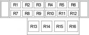
Ford F-650 - fuse box diagram - passenger compartment relay box
Ford F-750 – fuse box diagram – passenger compartment relay box
Number Description
R1
R2 Starter cutoff
R3 Run relay
R4 ABS warning indicator
R5 Hydraulic brake buzzer
R6 Eaton UltraShift
R7 Two-speed axle/Differential lock disable
R8 Air tank moisture removal valve
R9
R10 Hydraulic brake
R11 Eaton Ultrashift fan
R12 Starter cutoff
R13 Flasher
R14 Power window
R15 Full power buzzer
R16 Warning chime module

WARNING: Terminal and harness assignments for individual connectors will vary depending on vehicle equipment level, model, and market.
Ford F-650 (2004 – 2010) – fuse box diagram

Ford F-650 (2004 – 2010) – fuse box diagram

Year of production: 2004, 2005, 2006, 2007, 2008, 2009, 2010

Engine Compartment Fuse Box

Ford F-650 - fuse box diagram - engine compartment
Ford F-650 – fuse box diagram – engine compartment
Number Ampere rating [A] Description
F1 15 Main light switch
F2 30 Power seat (driver)
F3 30 Power seat (passenger)
F4 15 Washer pump relay, Washer pump motor
F5 15 Caterpillar / Cummins: Brake warning switch
F6 15 Caterpillar: Air intake heater
F7 15 Stoplamp switches, Brake pressure switches, Stoplamp relay
F8 25 Caterpillar: Fuel heater relay
Power Stroke 6.0L (’04-’07): Fuel heater relay
F9 20 ’06-’10: Inhibit relay, Engine ECM, Cluster, Transmission TCM, CJB Start (’07), CJB Run (’07), Starter cutoff (’10)
F10 15 ’04-’09: Heated drain valve
’10: Air tank moisture removal valve
F11 30 ’07-’10: Electronic trailer brake
F12 20 ’06-’10: Daytime Running Lamps (DRL), Blend door actuator, Climate mode, Back-up, Heated seats, Trailer ABS, Exhaust brake
F13 10 ’04-’05: Parking brake
F14
F15 7,5 ’04-’09: Body builder – trailer adapter stoplamps
F16 5 Hydraulic Brake: WABCO ABS
Air Brake: Bendix Air ABS
F17
F18 10 Fuel transfer pump
F19
F20 10 Power Stroke 6.0L (’04-’07): Engine ECM power relay
F21 10 ’04-’08: Hydromax motor input to GEM
F22 10 Power Stroke 6.0L (’04-’07): Engine IDM2 logic power
F23
F24
F101 30 Air Brake: Bendix Air ABS relay
Hydraulic Brake: Hydraulic brakes module
F102 20 Ignition switch to customer access
F103 50 ’04-’05: Ignition switch, Passenger compartment fuse box fuses 8, 9, 10, 11, 19, 20, 23, 24, 25, 29, 30, 31
20 ’06-’10: Ignition switch, Passenger compartment fuse box fuses 8, 9, 10, 11, 19, 29, 30
F104 20 Power point
F105 20 Door lock switches
F106 30 Main light switch, Multifunction switch, Passenger compartment fuse box fuses 16, 26 and 28, Headlamps, DRL relays
F107 50 Passenger compartment fuse box fuses 1, 2, 3, 4, 12, 13, 14, 15
F108 40 Cummins: Fuel heater relay
F109 40 Power window relay
F110 30 ’06-’10: Windshield wiper relay
F111 30 Park lamps relay, Park lamps, Body builder relay
F112 40 Blower motor relay, Blower motor
F113 30 Heated seats switches, Air ride seat (’09-’10)
F114 25 ’04-’09:
Hydraulic Brake: ABS ECU power
F115 40 ’04-’05: Ignition switch, Passenger compartment fuse box fuses 5, 8, 9, 10, 11, 21
20 ’06-’10: Ignition switch, Passenger compartment fuse box fuses 8, 9, 10 and 11, Starter motor relay (’06-’09)
F116 30 Turn relays and back-up lamp relay
F117 20 Stoplamp relay
F118 60 Trailer tow left, right and ABS fuse block (Hydraulic brake vehicles)
F119 60 Trailer tow fuse block, Stop/Tail/Marker lamps
F120 60 Trailer tow fuse block (Air brake vehicles), Left, right and ABS, Hydraulic HydroMax pump motor fuse relay
Relay
201 Washer pump relay
202 Wiper speed relay
203 Wiper run-park relay
204 ’04-’06:
Power Stroke 6.0L: Neutral start relay
Caterpillar / Cummins: Exhaust brake relay
’07-’10: Windshield wiper relay
205 ’04-’09: RH stop/turn relay
’10: Body builder relay, right turn
206 ’04-’09: LH stop/turn relay
’10: Body builder relay, left turn
207 ’04-’06:Drain valve heater relay
’07-’09:
Hydraulic Brake: ABS event relay
’10:
Air Brake: ABS event relay
Hydraulic Brake: Stop lamp relay
208 Back-up lamps relay, body builder relay (’10)
209 ’04-’07:
V8 engines: ECM ISO relay
Caterpillar / Cummins: Stop lamp relay
’08-’09: Stop lamp relay
’10: Auxiliary stoplamp relay
301 Fuel heater/transfer pump relay
302 Park lamp relay, body builder relay (’10)
303 Blower motor relay
304 Air Brake: ABS relay
Hydraulic Brake: Hydraulic modulator relay
Diode
501
502
503
Resister
401

Passenger Compartment Fuse Box

Ford F-650 - fuse box diagram - passenger compartment
Ford F-650 – fuse box diagram – passenger compartment
Number Ampere rating [A] Description
1 20 Horn relay
2 15 Hazard flasher
3 20 Cigar lighter
4 10 Data Link Connector (DLC), Engine diagnostic connector (’10), Parking brake warning (’07-’10)
5 15 Blend door actuator, Function selector switch assembly (’10), Trailer tow relay (’10), Trailer ABS (’05-’10), Daytime Running Lights (DRL), Climate mode (’07-’10), Heated seats, Exhaust brakes (’07-’10), Back-up lamps switch
6 10 ’04: Horn switch
7
8 5 Radio, GEM
9 5 Switch illumination (Headlamp, Power windows, Power door locks (’04-’07)), Power window switch LED and relay
10 15 Heated and lighted mirrors
11 30 ’04-’06:Wiper motor, Washer pump relay
5 ’07-’10: Wiper and washer systems
12 10 ’04-’09: Stop lamp switch (Hydraulic brake vehicles), Allison push-button shifter (’08-’09)
’10: Brake pedal position switch, Transmission shift selector, Stoplamp switch, Cruise switches
13 20 Cluster, Radio
14 14 Interior lamp relay
15 10 Interior lamp relay, Vanity mirror lamps, Map lamps, Generic Electronic Module (GEM)
16 15 Headlamp high beam, High beam indicator
17
18 5 Headlamp switch interior lighting
19 15 Engine control (all engines), Accelerator pedal (6.0L Power Stroke engine)
20 15 ’04-’06:Starter relay, GEM
5 ’07-’10: Starting system
21 10 Daytime Running Lights (DRL) resistor
22 15 Speed control feed (6.0L Power Stroke engine (’04)), Fuel transfer pump (’04), Air horn, Air solenoid 4–pack (Air horn, Air suspension dump, Differential lock axle and Two-speed axle)
23 10 Hazard flasher (Run)
24 15 ABS, Air dryer, Vacuum pump, Fuel heater relay
25 10 Function selector switch
26 10 Right hand low beam headlamp
27
28 10 Left hand low beam headlamp
29 10 Cluster (Power, Warning lamps), Gauges GEM, Hydraulic ABS relay, Air traction control, Hourmeter, Transmission temp
30 15 ’07-’10: Allison electronic transmission
31 15 ’04-’06:Allison transmission or ABS event
Relay
R1 Interior lamp relay
R2
R3 Horn relay
R4 One-touch window down relay
R5

Additional Relay Box No.2

Ford-F-650 - fuse box diagram - additional relay box 2
Ford-F-650 – fuse box diagram – additional relay box 2
Number Ampere rating [A] Description
1 30 Trailer tow ABS feed
2 30 Trailer tow park/marker lamps
3 30 Trailer tow stop lamps
4 30 Trailer tow turn/stop lamps (combined)
Trailer tow turn lamps (separate)
5
Relay
R1 Trailer tow ABS relay
R2 ’04-’07: Trailer tow stop lamp relay
’08-’10: Trailer tow marker lamp relay
R3 ’04-’07: Trailer tow park/marker lamp relay
’08-’10: Trailer tow stop lamp relay
R4 Trailer tow tail lamp relay
R5
R6
R7 ’04-’07:
Trailer tow left turn/stop lamp relay (combined)
Trailer tow left turn lamp relay (separate)
’08-’10: Trailer tow left turn lamp relay
R8 ’04-’07:
Trailer tow right turn/stop lamp relay (combined)
Trailer tow right turn lamp relay (separate)
’08-’10: Trailer tow right turn lamp relay


Passenger Compartment Relay Box (’10)

The relay center is located on the instrument panel behind the passenger side airbag panel.

Ford F-650 - fuse box diagram - passenger compartment relay box
Ford F-650 – fuse box diagram – passenger compartment relay box
Number Description
R1
R2 Starter cutoff
R3 Run relay
R4 ABS warning indicator
R5 Hydraulic brake buzzer
R6 Eaton UltraShift
R7 Two-speed axle/Differential lock disable
R8 Air tank moisture removal valve
R9
R10 Hydraulic brake
R11 Eaton Ultrashift fan
R12 Starter cutoff
R13 Flasher
R14 Power window
R15 Full power buzzer
R16 Warning chime module


WARNING: Terminal and harness assignments for individual connectors will vary depending on vehicle equipment level, model, and market.
Ford F-750 (2011 – 2015) – fuse box diagram

Ford F-750 (2011 – 2015) – fuse box diagram

Year of production: 2011, 2012, 2013, 2014, 2015

Passenger Compartment Fuse Box

Ford F-650 - fuse box diagram - passenger compartment
Ford F-750 – fuse box diagram – passenger compartment
Number Ampere rating [A] Description
1 20 Horn
2 15 Flasher relay
3 20 Power point
4 10 Data Link Connector (DLC), Engine diagnostic connector, Parking brake warning
5 15 Run relay
6
7
8 5 Radio, GEM
9 5 Power window relay
10 15 Heated mirrors
11 5 Wiper and washer systems
12 10 Transmission shift selector
13 20 Radio/SYNC®, Power mirrors
14 10 Interior lamp relay
15 10 Interior lamp relay
16 15 High beams, Indicator
17
18 5 Dimmer switch, Interior lighting
19 15 Engine control
20 5 Starting system
21 10 DRL resistor
22 15 Air horn, Air suspension dump, Two-speed axle, Driver-controlled locking differential
23 10 Flasher relay
24 15 ABS relay, Fuel heater relay, Air dryer
25 10 Blower motor relay
26 10 Right-hand low beam headlight
27
28 10 Left-hand low beam headlight
29 10 Cluster, GEM
30 15 Allison electronic transmission
31 15 Mirror fold relay
Relay
R1 Interior lamps
R2
R3 Horn
R4
R5

Engine Compartment Fuse Box

Ford F-650 - fuse box diagram - engine compartment
Ford F-750 – fuse box diagram – engine compartment
Number Ampere rating [A] Description
1 20 Upfitter switches (AUX 2 and AUX 4)/Trailer 12V socket pin
2 30 Power seat (driver)
3 30 Power seat (passenger)
4 15 Windshield washer relay, Washer pump motor
5 5 Brake warning switch (hydraulic brake vehicles only)
6 20 Upfitter switches (AUX 1 and AUX 3)
7 15 Brake pressure switches, ABS event relay
8 20 Diesel: DEF (Urea), Line heaters
9 20 Ignition switch, Starter cutoff
10 15 Air tank moisture removal valve
11 30 Electric trailer brake
12 20 Passenger compartment fuse box 5 and 21
13 15 Instrument cluster/Gateway module
14 20 Diesel: Nitrogen oxide sensor
15
16 5 Bendix® Air ABS
17
18 10 Fuel transfer pump
19 15 Gasoline: Powertrain control module power 1
20 10 Gasoline: Powertrain control module power 2
21 20 Gasoline: Powertrain control module power 3
22 20 Gasoline: Powertrain control module power 4
23
24
101 30 Bendix Air ABS relay (Air brake vehicles only)
Hydraulic brakes module (Hydraulic brake vehicles only)
102 20 Ignition switch
103 20 Ignition switch, Passenger compartment fuse box fuses 19, 29 and 30
104 20 Power point
105 20 Power door lock switches
106 30 Main light switch, Multi-function switch
107 50 Passenger compartment fuse box fuses 1, 2, 3, 4, 12, 13, 14 and 15
108 40 Diesel: Fuel heater
20 Gasoline: Fuel pump module
109 40 Power window
110 30 Windshield wiper
111 30 Body builder relay, Parking lamps
112 40 Blower motor
113 30 Heated seats, Air-Ride seat
114 20 Aftertreatment DCU
115 20 Ignition switch, Passenger compartment fuse box fuses 8, 9, 10 and 11
116 30 Left/Right turn relays, Back-up lamp relay
117 20 Stoplamps
118 60 Hydraulic brake vehicles (Trailer tow package only)
601 60 Trailer socket
602 60 Air brake trailer tow fuse block
30 Hydraulic brakes pump motor 2
Relay
201 Windshield washer relay
202 Wiper high/low relay
203 Wiper run/park relay
204 Windshield wiper relay
205 Body builder relay, right turn
206 Body builder relay, left turn
207 ABS event relay (Hydraulic brake vehicles only)
208 Body builder relay, back-up lamps relay
209 Auxiliary stoplamp relay
301 Diesel: Fuel heater/Fuel transfer pump relay
Gasoline: Fuel pump module
302 Body builder relay, parking lamps relay
303 Blower motor relay
304 Diesel: DEF (Urea) line heaters relay
Gasoline: Powertrain control module power VPWR1

Additional Fuse Box (Engine Compartment)

Number Ampere rating [A] Description
9925 30 Hydraulic brakes pump motor 1


Additional Relay Box

The relay center is located along the passenger side A-pillar on the right side of the footwell.

Ford F-650 - fuse box diagram - engine compartment additional box
Ford F-750 – fuse box diagram – engine compartment additional box
Number Description
R1 Spring applied hydraulic release warning chime module
R2 A/C compressor clutch
R3 Power windows
R4 Flasher (standard/LED)
R5 Upfitter relay 1
R6 Upfitter relay 2
R7 Headlights
R8 Cummins starter lockout
R9 Upfitter relay 3
R10 Starter
R11 Diesel: DCU
R12 Two-speed axle/Differential lock
R13 Door lock
R14 Air tank moisture valve
R15 DRL #1
R16 Heated mirrors
R17 Spare
R18 Upfitter relay 4
R19 Shift interlock/EPRNDL display
R20 Diesel: Selective Catalyst Reduction (SCR) system (NOx)
R21 Run
R22 Door unlock
R23 ABS warning indicator
R24 DRL #2
R25 Park lights
R26 Spare

Additional Relay Box No.2

Ford-F-650 - fuse box diagram - additional relay box 2
Ford-F-750 – fuse box diagram – additional relay box 2
Number Ampere rating [A] Description
1 30 Trailer tow ABS feed (non electric trailer brake vehicles only)
2 30 Trailer tow park/marker lamps
3 30 Trailer tow stop lamps
4 30 Trailer tow turn/stop lamps (combined)
Trailer tow turn lamps (separate)
5
Relay
R1 Trailer tow ABS relay (non electric trailer brake vehicles only)
R2 Trailer tow marker lamp relay
R3 Trailer tow stop lamp relay
R4 Trailer tow tail lamp relay
R5
R6
R7 Trailer tow left turn lamp relay
R8 Trailer tow right turn lamp relay

WARNING: Terminal and harness assignments for individual connectors will vary depending on vehicle equipment level, model, and market.