Toyota ProAce (2016 – 2018) – fuse box diagram

Toyota ProAce (2016 – 2018)- fuse box diagram

Year of production: 2016, 2017, 2018

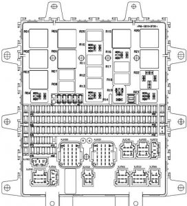
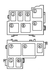
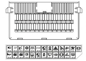
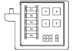
Passenger Compartment Fuse Box
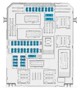
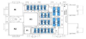
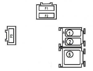
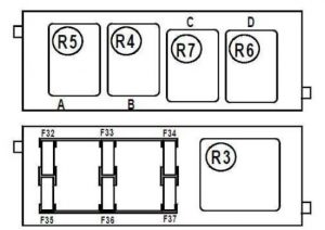
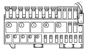
Toyota ProAcea - fuse box diagram - passenger compartment box 1
Toyota ProAcea – fuse box diagram – passenger compartment box 1

Fuse Ampere rating [A] Functions
F1 3 Full: Ignition switch, Push starter ADM
10 ECO: Photochromic interior mirror, Fuel additive pump, DAEH, Knurled wheel ASR+, CTC clutch
F2 3 Full: Steering wheel angle sensor
F3 3 Full: Instrumentation socket, Joystic Comelec
5 ECO: BSG TC
F4 7,5 Full: Instrumentation socket, Diagnostic socket, Brake dual-function switch, Centralized voltage maintenance device
15 ECO: Horn
F5 5 Full: Multifunction screen, Reversing camera, ECU’s parking assistance
20 ECO: Screen wash pump front/rea
F6 15 Full: Not used
20 ECO: Screen wash pump front/rear
F7 10 Full: Audio amplifier, Rear BCC
10 ECO: Front 12V socket
F8 20 Rear windscreen wiper
F9 5 Interior lamp
F10 30 Front and rear external/ internal mass power engine locks + Fuel catch
F11 30 Front and rear internal/external locks engine supply Fuel catch
F12 3 Full: Alarm, APV alarm strain
7,5 ECO: CTC main stop, DMTC, Diagnostic socket
F13 3 Full: Module boiler control, Strain APV
10 ECO: Front mux, CRT, BCC, VTH, MCP
F14 15 Full: Not used
5 ECO: BTA, Alarm
F15 5 ECO: Diagnostic socket
F16 5 Full: Not used
3 ECO: Stop switch, DMTR
F17 10 Full: 12V current socket trunk or load area
5 ECO: CMB
F18 5 Full: Autonomous telematics box
ECO: Passenger compartment coolant circuit heater
F19 5 Full: Rastreador
3 ECO: BSG, HDC, VCI
F20 15 Full: Relay compartment fusebox 3
F21 3 Full: Nomadic lamp charging, card reader
ECO: Steering lock, Push DEM (ADML
F22 3 Full: Glove compartment lighting, Card reader
ECO: CDPL, CVM
F23 3 Full: Platinum mirrors control gate driver, Taxi, Parking assistance with blind spot monitoring
5 ECO: Seat belt not fastened warning light displays
F24 5 Full: Generic servitude case, Module de communication sous volant (CV00)
ECO: AAS, Rear camera
F25 5 Full: Projector corrector switch, Electrochromic rearview mirror
ECO: Air bag
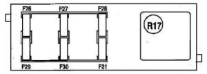
F26 3 Full: Instrumentation sockets, Driver and passenger unfastened indicator display, Strain APV
ECO: CAV
F27 3 Full: Light rain sensor, Switch under the steering wheel
5 ECO: Heater control module
F28 10 Full: Front gear shift MCP- BCC, Front facade MUX, Audio- Head up display
ECO: Rastreador
F29 5 Full: Engine wiring housing (PSF1)
20 ECO: RD6, NAC, RCC
F30A 15 Full: Audio APV strain
F30B 15 Full: Audio APV strain
F31 5 Full: ECU’s air bag
15 ECO: 2nd build audio system
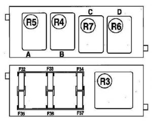
F32 5 Full: Left and right sliding side door
15 ECO: Cigar lighter or 12V socket
F33 15 Full: Cigar lighter or 12V socket
F34 3 Full: Housing generic servitude
5 ECO: Taxi unit, AAS with SAM, rear view mirror adjusting, Transformer APC body
F35 5 Full: Combinated ECU
ECO: Headlamp height adjustment, BCP, coolant temperature level, Diagnostic socket
F36 20 Full: Audio
5 ECO: Glove box lighting, Reloads device, map-reading light
RELAYS
R1 Power + ACC
R2 Power + CAN
R3 Full: Rear screen wipe
ECO: Supply +APC
R4 Full: Engine front and rear extriors/interiors locks
ECO: Rear wiper relay
R5 ECO: Windscreen wash pump
R6 ECO: Rear screen wash pump
R7 ECO: Horn
R8 ECO: Engine front and rear extriors/interiors locks
R13 ECO: Engine front and rear extriors/interiors locks

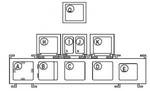
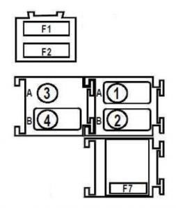
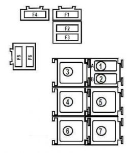
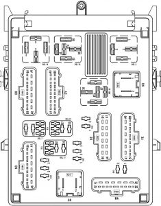
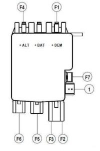
Passenger Compartment Fuse Box No.2

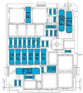
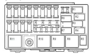
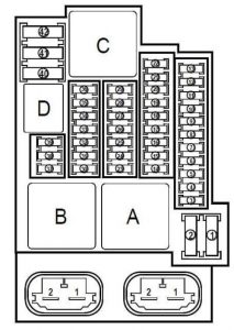
Toyota ProAcea - fuse box diagram - passenger compartment box 2
Toyota ProAcea – fuse box diagram – passenger compartment box 2
Fuse Ampere rating [A] Functions
F1 40 Heated rear screen
F2 7,5 Full: Heated mirror
10 ECO: Heated mirror
F3 20 Full: 230V Current socket
30 ECO: Electric front windows
F4 15 Full: Folding rearview mirror
30 Full: Folding rearview mirror, Si 2 LVE
20 ECO: 12V socket, Kit APV 230V
F5 30 Full: Not used
20 ECO: BSG RQ
F6 30 Full: Front electric window engine
10 ECO: Fold-back mirrors
F7 30 Full: Heated seat
10 ECO: Fold-back mirrors
F8 25 Full: Audio amplifier
40 ECO: Not used
F9 20 Full: Dual screen wipe AR
15 ECO: 12V plug RG2
F10 15 Full: 12V current socket
3 ECO: BSG
F11 5 Full: Trailer servitude generic case 7/13 tracks
20 Full: Trailer servitude generic case 7/13 tracks
ECO: Heated cover, Double rear screen wipe
F12 40 Full: Driver electrical seat
20 ECO: Heated seat or heated bench seat
F13 40 Full: Not used
F14 30 Full: Passenger electrical seat
F15 25 Full: Not used
F16 5 Full: Not used
F17 10 Full: Not used
F18 25 Full: Not used
F19 7,5 Full: Not used
F20 3 Full: ECU’s parking assistance
F21 3 Full: Power left and right sliding side door
F22 20 Full: 12V current socket glove box, Kit APV 230V
F23 3 Full: Trailer servitude generic case
RELAYS
R1 Full: Right folding mirror
ECO: Rear screen + mirror demisting
R2 Full: Left folding mirror
ECO: Electric windows
R3 Full: Heated mirror and rear
ECO: Fold-back mirrors
R4 ECO: Fold-back mirrors
R5 ECO: Heated cover
R6 ECO: 12V socket
R7 ECO: Heated seat

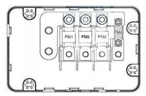
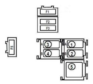
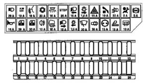
Engine Compartment Fuse Box (ECO)

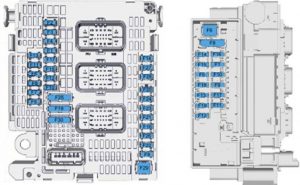
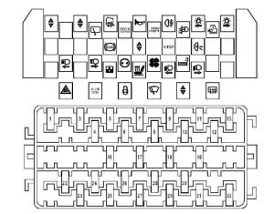
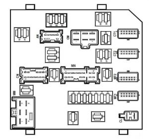
Toyota ProAcea - fuse box diagram - engine compartment (ECO)
Toyota ProAcea – fuse box diagram – engine compartment (ECO)
Fuse Ampere rating [A] Functions
F1 40 Air conditioning blower
F10 15 Engine ECU
F11 20 Engine ECU
F12 5 Engine ECU, diagnostic socket, Fan unit, STT
F13 5 BSI
F14 5 Battery charge status unit
F15 20 BSG
F16 15 Front fog lamps
F17 5 Diagnostic relay, BFRM
F18 10 RH main beam
F19 10 LH main beam
F2 60 LHD: ESP ECU
50 RHD: ESP ECU
F20 30 Engine ECU, booster pump (if EP6FDT)
F21 30 Starter motor
F22 40 LHD: Gearbox MCP, power steering electropump unit
30 RHD: Gearbox MCP, power steering electropump unit
F23 40 Centralised voltage maintaining system
F24 40 Passenger compartment fuse box (BFH5)
F25 40 Passenger compartment fuse box (BFH5)
F26 15 Gearbox MCP
F27 25 BSI
F28 30 Injector power supply SCR, NOx sensor
F29 40 Windscreen wiper
F3 80 Passenger compartment fuse box (BFH3)
F30 125 Power steering electropump unit
F31 80 Protection switching unit
F32 80 BFM4
F4 30 ESP ECU
F5 50 BSI
F6 60 2-speed cooling fan (GMV) control unit
F7 70 BSI
F8 15 Engine ECU (if DV6FUC or EP6FDT), booster pump (if DV6F or DW10F)
F9 15 Engine ECU
PR Engine ECU
PU Engine ECU
RELAYS
R1 SCR unit module power supply
R2 Heated windscreen wash jets
R3 Heat pre-conditioning service
R4 Front fog lamps
R5 Air conditioning blower
R6 Starter motor
R7 Windscreen wiper
R8 Windscreen wiper
R9 Main beam headlamps


Number Ampere rating [A] Functions
MF1 80 Pre-post heating
MF2 20 BSG
MF3 20 Headlamp wash
MF4 20 BFRM

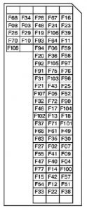
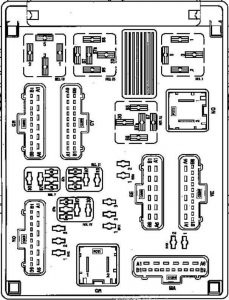
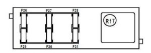
Engine Compartment Fuse Box (Full)

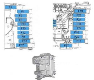
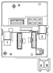
Toyota ProAcea - fuse box diagram - engine compartment (FULL)
Toyota ProAcea – fuse box diagram – engine compartment (FULL)


Number Ampere rating [A] Functions
F1 5
F5 5
F6 40
F8 30 Diesel Euro 6: Sensor NOX and SCR
F9 10
F10 5
F11 5
F12 15 Wiper, Manual gearbox, Ax6 III ECU
F13 20 Coolant and passenger compartment heater
F14 5 COMELEC Ax6 III ECU’s
F15 15
F16 15
F17 10
F18 5 Brake dual-function switch
F19 5
F1 15 Control of Centralised Power Switch relay 1032, Diesel injectors
F2 5 Control of cooling fan unit relay, Bike fan, unit
F3 5 Steering relays, Centralized voltage maintenance device, Reversible alternator
F4 5 Injector SCR
F5 15 Pump driven gavage
F6 20 Intake air flow meter, Solenoid Bypass interchange EGR
F7 10 Diesel pump solenoid flow control, Proportional solenoid TGV
F8 10 Water in diesel detector sensor Solenoid oil pump
F9 10 Electronic immobilizer
F10 5
F11 15 Steering protection switch housing 3, Micro projector engine correction, Fuel additive pump Sliding side power door
F12 5 Heating nozzle
F13 5 Rastreador DMTR
F14 25 Powerful pump mass Front and rear screen wash
F15 5 Calculating ARTIV, Diagnostic socket, Clutch switch, Coolant level sensor, Power steering computer
F16 20 Air conditioning pump group AR
F17 10 Built in system interface
F19 30 Front screen wipe
F20 15 Pump power, Front and rear screen wash
F21 20 Headlight washer pump
F22 15 Sonor alarm
F23 15 Right road lights
F24 15 Left road lights
F25 30
F26
F27 5
F28 5
F29 30 Starter
F30 30 Diesel heater, Blow-by diesel heater
RELAYS
R1 Diesel engine ECU
R2 Driving BSM
R3 Driving BSM
R4 Engine ECU, Steering relay CPC (1032), Centralized voltage maintenance device, Reversible alternator, Engine blower
R5 Engine ECU, Additive pump FAP (DV6C-DV6D)
R6 Engine ECU, Additive pump FAP (DV6C-DV6D)
R7 Starter
R8 Front screen wipe
R9
R10 Front and rear screen wash pump
R11 Headlamp wash pump
R12 Sonor alarm
R13
R14 Left road lights
R15 Right road lights
R16
R17


Toyota ProAcea - fuse box diagram - engine compartment (FULL)
Toyota ProAcea – fuse box diagram – engine compartment (FULL)
Number Ampere rating [A] Functions
F1 80 Relay compartment fusebox 3
F2 70 Buil in system interface
F3 50 ESP ECU’s
F4 20 Generic servitude case
F5 30 ESP ECU’s
F8 125 Power steering electric pump
F9 125 Fuses servitude platinum
F10 60 Built-in system interface
F11 40 Relay compartment fusebox 5 trailer
F12 60 Relay compartment fusebox 3
F13 60 Relay compartment fusebox 2
F16 70 Pre -post heating box
F17 100 Maxi fusebox 4
F18 40 AR Additional air conditioning group
F19 30 Starter
40 Centralized voltage maintenance device
F20 40 Taxi Relay compartment fusebox 5
F21 20 Generic servitude case
F22 5 Battery charge case
F23 60 Control housing GMV
F24 40 Air conditioning kicker AV
F25
F26 30 MCP or Ax6 III ECU’s gearbox
F27 80 Protection switching box 3


Number Ampere rating [A] Functions
F36 20 ECO: BSG
Full: Trailer servitude generic case / Caravan
10 Taxi: Taxi radio
F37 20 ECO: BSG
Full: Trailer servitude generic case / Caravan
5 Taxi: Taxi screen
F38 20 ECO: BSG
Full: Trailer servitude generic case / Caravan
5 Taxi: Taxi recorder
F39 5 Taxi: Taxi printer
F40 5 Taxi: Taxi time recorder requirements

WARNING: Terminal and harness assignments for individual connectors will vary depending on vehicle equipment level, model, and market.

Toyota Corolla AE86 (1983 – 1987) – fuse box diagram

Toyota Corolla AE86 (1983 – 1987) – fuse box diagram

Year of production: 1983, 1984, 1985, 1986, 1987

Passenger Compartment

LDH

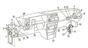
Toyota Corolla - fuse box diagram - passenger compartment (LHD)
Toyota Corolla – fuse box diagram – passenger compartment (LHD)

Number Description
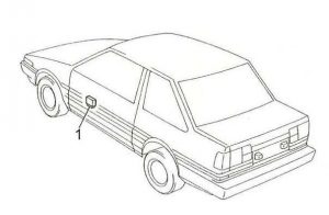
1 Fuse box
2 Starter realy
3 Cruise Control Computer
4 Retract Control Relay
5 Electrical Idle-up Cut Relay
6 Magnet Clutch Relay
7 Charge Light Relay
Hazard Red Indicator Relay
8 Seat Belt Warning Relay
9 Circuit Opening Relay (Fuel Pump)
10 4A-C: Emission Control Computer
EFI ECU
11 Junction Block
12 Fuse: A/C – 10A (A/C Switch, A/C Amplifier)
13 Heater Circuit Breaker (Heater Relay, Blower Motor)
14 Heater Relay
15 Junction Block
16 O/D Relay (Automatic Transmission)
17 Light Retainer Relay
18 Turn Signal Flasher
19 Rear Fog Light Relay
20 Retract Control Relay
21 Seat Belt Warning Relay
22 Idle-up Computer (EFI)
23 Chime

RDH

Toyota Corolla - fuse box diagram - passenger compartment (RHD)
Toyota Corolla – fuse box diagram – passenger compartment (RHD)
Number Description
1 Fuse box
2 Turn Signal Flasher
3 Junction Block
4 Heater Relay
5 Fuse: A/C – 10A (A/C Switch, A/C Amplifier)
6 Junction Block
7 Heater Circuit Breaker (Heater Relay, Blower Motor)
8 EFI ECU
9 Circuit Opening Relay (Fuel Pump)
10 Idle-up Computer (EFI)
11 O/D Relay (Automatic Transmission)
12 Rear Fog Light Relay

Passenger Compartment Fuse Box

Toyota Corolla - fuse box diagram - passenger compartment fuse box
Toyota Corolla – fuse box diagram – passenger compartment fuse box
Fuse Ampere rating Description
1 RADIO NO.2 7,5 Radio and Tape Player, Remote Control Mirrors
2 RTR 10 Retract Control Relay
3 IGN 7,5 Engine Main Relay, EFI Main Relay, Charge Warning Light
4 TURN 7,5 Turn Signal Flasher, Turn Signal Light, Turn Signal S/W
5 STOP 15 Stop Light S/W, Stop Light, Cruise Control Computer, ECU
6
7 CIG 15 Cigarette Lighter, Digital Clock
8 GAUGE 7,5 Combination Meter, Back-up Light S/W, Back-up Light, O/D Relay, O/D Off Indicator, Defogger S/W, Defogger Relay, Light Retainer Relay, Heater Relay, Cruise Control S/W, Seat Belt Warning Relay, Seat Belt Warning Light
9 TAIL RH 10 Clearance Light RH, Taillight RH, Licence Plate Light, Radio Light, Cigarette Lighter Light, Heater Control Light, Combination Meter Light, A/T Indicator Light, O/D Main S/W Light, Headlight Cleaner Relay
10 DOME 7,5 Interior Light, Map Light, Door Warning Light, Luggage Room Light, Digital Clock, Light Retainer Relay, Unlock Warning S/W, Seat Belt Relay, Rear Fog Light
11 ECU-IG 30 Sun Roof Motor
12 PWR 30 Power Window Relay
SEAT HEATER 20 Seat Heater
13 TAIL 15 Clearance Light, Taillight, Licence Plate Light, Radio Light, Cigarette Lighter Light, Heater Control Light, Combination Meter Light, A/T Indicator Light, Side Marker Light, O/D Main S/W Light, Wiper S/W Light, Defogger S/W Light, Digital Clock, Headlight Cleaner Relay
TAIL LH 10 Clearance Light LH, Taillight LH
14 WIPER 20 Washer Motor, Wiper Motor, Rear Wiper Motor, Rear Washer Motor, Headlight Cleaner Relay
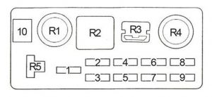
R1 Rear Window Defogger Relay
R2 Taillights Relay
R3 Circuit Breaker: Rear Window Defogger (LHD: 30A, RHD: 20A)

Toyota Corolla - fuse box diagram - passenger compartment fuse relay
Toyota Corolla – fuse box diagram – passenger compartment relay
Number Description
1 Power Window Relay

Engine Compartment

Toyota Corolla - fuse box diagram - engine compartment
Toyota Corolla – fuse box diagram – engine compartment
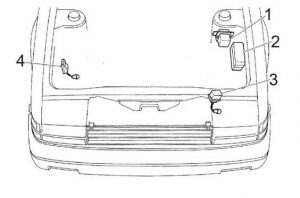
Number Description
1 CMH Relay / Regulator
2 Fuse box
3 Retractor Relay
4 Headlight Cleaner Relay

Engine Compartment Fuse Box

Toyota Corolla - fuse box diagram - engine compartment fuse box
Toyota Corolla – fuse box diagram – engine compartment fuse box
Fuse Ampere rating [A] Description
1 CHARGE 7,5 Charge Warning Light, Charge Light Relay, Choke Heater
2 HEAD LH 10 Left−hand Headlight
HEAD LH HI 10 Left−hand Headlight (high beam), High Beam Indicator Lamp
3 HEAD RH 10 Right−hand Headlight
HEAD RH HI 10 Right−hand Headlight (high beam)
4 HEAD LH LO 10 Left−hand Headlight (low beam)
5 HEAD RH LO 10 Right−hand Headlight (low beam)
6 HAZ-HORN 10 Horn, Hazard S/W, Turn Signal Flasher
7 ENGINE 10 Alternator, Charge Light Relay (4A-C), Fuel Cut Solenoid, Emission Control Computer, OVCV, EBCV, CMH Relay, Secondary Slow Cut
8 EFI 15 EFI Main Relay, ECU, Circuit Opening Relay
9 RADIO NO.1 10 Radio and Tape Player
10 RTR 30 Retract Relay
Relay
R1 Engine Control Unit (EFI MAIN)
R2 Engine Main
R3 Short Pin
Dimmer
R4 Headlight
R5 Short Pin

Fusible Link Box (Battery + Terminal)

Number Ampere raing [A] Description
1 AMI 60 Engine Main Relay, Ignition S/W (AM1), Alternator, Defogger Relay, Taillight Relay, Headlight Cleaner Relay
80 4A-GEC: Engine Main Relay, Ignition S/W (AM1), Alternator, Defogger Relay, Taillight Relay, Headlight Cleaner Relay
2 AM2 30 Ignition S/W (AM2)
3 CMH 40 CMH, CMH Relay

Fusible Link Box (Near the Battery)

Number Description
1 FL 0.5G Headlight Relay, Dimmer Relay

WARNING: Terminal and harness assignments for individual connectors will vary depending on vehicle equipment level, model, and market.77

Renault Magnum (2001 – 2005) – fuse box diagram

Renault Magnum (2001 – 2005) – fuse box diagram

Year of production: 2001, 2002, 2003, 2004, 2005

Fuse box

Renault Magnum - fuse box diagram - instrument panel
Renault Magnum – fuse box diagram – instrument panel
Function Number Ampere rating [A]
Trailer socket, 7-pin type “EBS”
Trailer socket, 7-pin type 24 S
Engine preheating control
Electric or hydraulic retarder control
F1 10
RH side/parking lights
RH marker lights
RH central marker lights
F2 10
LH side/parking lights
LH marker lights
LH central marker lights
F3 10
Trailer side/parking lights F4 10
Available power supply (lighting)
Available power supply (roof light bank)
F5 10
Dashboard instruments lighting
Switch lighting Headlamps wash time-delay relay
F6 10
Fog light(s)
Fog lights warning light
F8 10
Fog driving lights
Fog driving lights warning light
F9 10
RH main beam headlight F10 10
LH main beam headlight
Main beam headlights warning light
F11 10
LH dipped beam headlight
Dipped beam headlights warning light
F12 10
RH dipped beam headlight F13 10
Windscreen wiper relay
Anti-theft alarm ECU
F15 10
Anti-theft electronic box
“AIRBAG” ECU
Defrosting rearview mirror control
Air pressure gauge
Reversing buzzer
F16 10
Air conditioning F18 20
“EBS” ECU F20 20
Power supply (after master switch) F21 15
Independent heater
Ventilation control box
Independent heater programming control
Main water circuit solenoid valve
3-level air conditioning pressure controller
Air conditioning relay
F22 30
Step light
Overhead light(s)
Voltage dropper (telecommunications)
Map reader
F23 20
Gearbox ECU “ASTRONIC” F24 20
Tachograph clock F25 5
Trailer socket, 7-pin type “EBS” F26 20
Stop lights
Trailer stop lights
F27 10
Hydraulic retarder ECU F28 10
LH swivelling defrosting rearview mirror
RH swivelling defrosting rearview mirror
F29 10
Headlamps adjustment motors
Radio
F30 10
Windscreen wiper motor
Windscreen washer pump
Headlamps washer pump
F32 20
Diagnostics socket
Suspension ECU
F33 10
Radio tuner + 24 Volts power supply
Independent heater programming control
Anti-theft alarm siren
F34 10
Available power supply (after ignition key) F35 10
Horn 2-tone horn solenoid valve
Self-tracking axle electrovalve
Roof air vent motor
F37 20
Principal display F38 5
Available relay(s) F40 10
Gearbox ECU “ASTRONIC” F42 10
Trailer + 24 Volts power supply
Onboard management prearrangement
Working spotlamp (tractor)
F43 15
Cab tilt pump F44 30
Passenger side electric door striker
Driver side electric door striker
Flasher unit Hazard lights control
Doors central locking box
Anti-theft alarm ECU
F45 20
Air dryer heater
Centralized lubrication timer
Self-tracking axle safety relay
F46 20
Suspension ECU
Suspension remote control box
Rear drive axle air springs pressure sensor
F47 10
Reversing lights relay F49 10
Refrigerator F50 20
Heated driver’s seat
Heated passenger seat
Voltage dropper (12V socket)
“SAE” plug socket
Cigar lighter
Refrigerant cylinder-holder
F51 20
Video available power supply F53 10
Front sun blind motor
Side sun blind motors
F54 10
Available power supply (after ignition key)
Available relay(s)
F55 10
Window winder motor F56 20
Vehicle master ECU
Tachograph
F57 10
“EUP” ECU
Exhaust brake electrovalve
F58 20
“EBS” ECU F60 5
Hydraulic retarder ECU
Electric retarder ECU
F86 10

Table of relays on connection unit

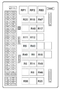
Function Number Ampere ratting [A]
After ignition power supply relay № 1 RP1 50
After ignition power supply relay № 2 RP2 50
Side / parking lights relay R5 20
Comfort accessories relay R6 20
Lighting relay R8 20
Fog driving lights relay R9 20
Fog lights relay R10 20
Dipped beam headlights relay R11 20
Main beam headlights relay R12 20
Stop lights relay R14 20
Preheating relay № 2 R16 20
Available relay № 1 R17 20
Defrosting rearview mirrors relay R20 20
Windscreen wiper relay R40 20
Reversing lights relay R40 20
“VECU / EECU” ECU power supply relay R43 20
Air conditioning compressor relay R46 20
Available relay № 2 R47 20
Available relay № 3 R48 20
Conditioned air relay R49 20
Headlamp washer time-delay relay R53
Self-tracking axle safety relay R55 20


Table of relays away from connection unit

Function Number Ampere ratting [A]
Preheating relay R15 100
Cab tilt mechanism relay RP10 50


Table of diodes on connection unit

Function Number
Alarm diode D5
Day running lights diode D6
Day running lights diode D7
Alarm diode D72
Air conditioning diode D86

Note: The connection unit diodes are not accessible


Fuses located in battery compartment

Renault Magnum - fuse box diagram - battery compartment
Renault Magnum – fuse box diagram – battery compartment
Function Number Ampere ratting [A]
Flasher unit
Independent heating
Onboard radio
Alarm
Central closing
F1 25
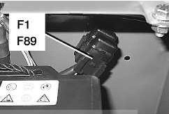
Tachograph (non ADR) F89 5
Tachograph (ADR) F89 1

Fuses in fuse box (1) located in battery compartment

Renault Magnum - fuse box diagram - battery compartment
Renault Magnum – fuse box diagram – battery compartment
Function Number Ampere ratting [A]
Cab power supply FM1 125
Electric tail-lift FM2 200
Engine intake air preheating FM3 125
FM4 40

WARNING: Terminal and harness assignments for individual connectors will vary depending on vehicle equipment level, model, and market.
Renault Premium DXI450 – fuse box diagram

Renault Premium DXI450 – fuse box diagram

Year of production:

Fuse box

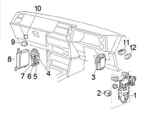
Renault Premium DXI450 - fuse box diagram
Renault Premium DXI450 – fuse box diagram
Function Number A
Principal information display
Cab tilting safety and authorization relay
Cab tilting motor power supply relay
F03 7,5
Principal information display F04 5
Headlamps wash pump motor F05 30
Principal information display
Tachograph
F06 5
Vehicle management ECU F07 5
Principal information display
Engine immobilizer ECU
Alarm ECU
Doors central locking ECU
Air production management ECU
F08 5
Bodybuilder pre-arrangement management ECU F09 5
Air conditioning ECU F10 30
Hydraulic retarder ECU
Electric retarder ECU
F11 10
Gear selector ECU
Automatic transmission ECU
F12 15
Lighting and signalling management ECU
Windscreen wipers motor time-delay relay
Windscreen wash pump motor
Windscreen wipers drive motor
F13 20
Cigar lighter F14 15
Vehicle diagnostic socket
Vehicle data extraction socket
F15 5
Selection control
Inter-wheel diff. lock warning light
Rear wheels diff lock electrovalve
PTO engagement electrovalve N° 1
PTO engagement electrovalve N° 2
PTO engagement electrovalve № 3
Inter-axle diff. lock electrovalve
F16 10
RH main beam headlight F17 10
Electric horn
Air horn
F18 10
Air conditioning ECU F19 5
Radio set
Alarm ECU
Doors central locking ECU
F20 10
ABS/EBS trailer socket F21 20
Driver’s side single overhead light
Front passenger’s side single overhead light
RH upper overhead lighting (door)
Driver’s reading spotlight
Front passenger’s reading spotlight
Bottom bunk overhead lighting
LH upper overhead lighting (door)
LH overhead lighting (ambience)
RH overhead lighting (ambience)
Top bunk overhead lighting
Driver’s side stepwell lighting
Front passenger’s side stepwell lighting
F22 10
Piloted axle lockover angle sensor
Air suspension ECU
Piloted axle ECU
F23 5
Fuel heater resistor № 2 F24 20
Available power supply (equipment in “road” position warning pictogram)
Available power supply (lighting)
Equipment in unlocked position warning light
Equipment lighting information tell-tale light
15-pin trailer socket
F25 10
Available power supply (after ignition) F26 15
Driver’s door window winder motor
Front passenger’s door window winder motor
F27 20
EBS braking management ECU F28 20
Automatic transmission gear selector
Onboard management interface ECU
F29 10
Lighting and signalling management ECU F30 30
Cab temperature regulation ECU
Alarm ECU
Air/water add-on heater
Air/air add-on heater
Air conditioning ECU
F31 20
Available power supply (after master switch) F32 10
Cab tilting motor F33 30
Onboard management interface ECU F34 3
Lighting and signalling management ECU F36 10
Voltage converter (24V / 12V – 15A) for audio communication system
Radio set
F37 10
Extra signalling lights warning light
Working spotlight
F38 10
Vehicle management ECU
LH defrosting rearview mirror resistor
RH defrosting rearview mirror resistor
Heated and swivelling rearview mirror power supply relay
Windscreen defrosting control relay
F39 15
Engine management ECU
Starter
Starting relay
Air preheating relay
Engine brake N° 1 solenoid valve
Exhaust brake solenoid valve
Range change electrovalve
Splitter control electrovalve
Engine cooling fan speed regulation solenoid valve
F40 30
Starter
Starting relay
Engine brake N° 1 solenoid valve
Engine brake N° 2 solenoid valve
Exhaust brake solenoid valve
Range change electrovalve
Splitter control electrovalve
F41 15
Air preheating relay
Engine cooling fan speed regulation solenoid valve
F42 10
24 Volts power supply socket
Automatic gearbox diagnostic socket
F43 15
Revolving beacon N° 1
Revolving beacon N° 2
Revolving beacons power supply relay
F46 15
Air production management ECU F47 7,5
Brake holding enabling control
EBS braking management ECU
F48 3
Air suspension ECU
Vehicle power supply management ECU (ADR)
F49 5
Piloted axle ECU F51 5
Automatic transmission gear selector
Engine immobilizer ECU
Cab emergency stop control
Vehicle management ECU
After ignition power supply relay N° 1
After ignition power supply relay N° 2
After ignition power supply relay N° 3
Accessories power supply relay N° 1
Accessories power supply relay N° 2
Alternator circuit earthing relay (ADR)
Alternator circuit draw resistor
Vehicle diagnostic socket
F52 10
Onboard management ECU F54 10
Hydraulic retarder ECU F57 10
Cab emergency stop control
Alternator circuit earthing relay (ADR)
F58 3
Pre-arrangement for onboard management (ECU)
Brake holding enabling control
Reversing lights power supply relay
F59 10
Voltage converter (24V / 12V) for information technology pack F61 15
24 Volts power supply socket F63 15
15-pin trailer socket F64 10
Tool compartment light
Front grille lighting
Electric roof air vent motor
F66 10
Gear selector ECU
Automatic transmission ECU
F67 20
Voltage converter (24V / 12V – 10A) for audio communication system
Voltage converter (24V / 12V – 15A) for audio communication system
Voltage converter (24V / 12V) -12 and 24 Volts integrated sockets
Refrigerated compartment
Refrigerator
Extra 24 Volts power supply socket
F68 20
ABS/EBS trailer socket F70 10
Available power supply (after ignition) F71 15
Main beam headlights warning light
LH dipped beam headlight
F72 10
Available power supply (alternator information, engine running)
RH heated seat unit
LH heated seat unit
F75 15
Vehicle hour-meter
Air/air add-on heater
Alternator circuit earthing relay (ADR)
Air/water add-on heater solenoid valve
F76 10
Available power supply (after master switch) F77 15
Lighting and signalling management ECU
Rear fog lights power supply relay
Main beam headlights power supply relay
Fog driving lights power supply relay
Switches night lighting power supply relay
Fog lights cut-off relay if main beam headlights on
F90 3
RH clearance light № 1
RH clearance light № 2
LH front side/parking lights
RH clearance lights № 3
RH clearance lights № 4
RH rear side/parking lights
Roof LH side/parking lights
Anti-glare strip-mounted LH marker lights
Vehicle power supply management ECU (ADR)
F91 10
RH front side/parking lights
LH clearance lights № 1
LH clearance lights № 2
LH clearance lights № 3
LH clearance lights № 4
LH rear side/parking lights
Roof LH side/parking lights
Anti-glare strip-mounted RH marker lights
F92 10
Available power supply (RH rear marker light(s)
15-pin trailer socket
F93 10
Available power supply (LH rear marker light(s)
15-pin trailer socket
F94 10
Instruments and controls night lighting F96 3
Available power supply (night lighting) F97 5
Main beam headlights warning light
Fog driving lights warning light
RH main beam headlight
LH dipped beam headlight
LH fog driving light
RH fog driving light
F100 15
Fog lights warning light
RH rear fog light
LH rear fog light
15-pin trailer socket
F101 10
Principal information display
RH long range driving light
LH long range driving light
F102 10
Available power supply (reversing information)
Reversing buzzer inhibition control
LH reversing lights
RH reversing lights
External horn
15-pin trailer socket
F103 10
LH stop lights
RH stop lights
15-pin trailer socket
F104
Nitrogen oxides gases concentration sensor
AdBlue supply management pump module
Engine water circuit by-pass solenoid valve
F107 10
Air/air add-on heater F108 20

Relays

Renault Premium DXI450 - fuse box diagram - relays
Renault Premium DXI450 – fuse box diagram – relays
Function A Number
After ignition power supply relay N°1 50 R01
After ignition power supply relay N°2 50 R02
After ignition power supply relay N°3 50 R03
Heated and swivelling rearview mirror power supply relay 10 R04
Alternator controlled power supply relay (engine running) 20 R05
RH and LH side/parking and marker lights power supply relay 20 R06
Switches night lighting power supply relay 10 R07
Main beam headlights power supply relay 10 R08
Alternator circuit earthing relay (ADR) 10 R09
Add-on heater power supply relay 10 R10
Cab tilting safety and authorization relay 10 R11
RH and LH side/parking and marker lights power supply relay (trailer and bodybuilder) 10 R12
Stop lights power supply relay 10 R13
Long range driving lights power supply relay 10 R14
Windscreen wipers motor time-delay relay 20 R15
Automatic transmission management ECU power supply relay 10 R16
Starting relay 10 R17
Rear fog lights power supply relay 10 R18
Air suspension power supply relay 10 R19
Vehicle and engine ECUs power supply relay 50 R20
Accessories power supply relay N° 1 50 R21
Accessories power supply relay N° 2 50 R22
Fog driving lights power supply relay 10 R23

WARNING: Terminal and harness assignments for individual connectors will vary depending on vehicle equipment level, model, and market.
Renault Kangoo (1997 – 2007) – fuse box diagram

Renault Kangoo (1997 – 2007) – fuse box diagram

Year of production: 1997, 1998, 1998, 1999, 2000, 2001, 2002, 2003, 2004, 2005, 2006, 2007

Fuse box in passenger compartment

This unit is located in the passenger compartment on the driver’s side.

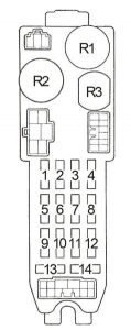
Renault Kangoo - fuse box diagram - passenger compartment
Renault Kangoo – fuse box diagram – passenger compartment
Number Ampere rating [A] Description
F1
F2 10 Electric door mirror control, Clock, Radio, – Central display
F3 15 Light for luggage compartment, Courtesy lights, Courtesy light console, Side door ECU (except mercosur)
F4 30 Consumer cut-out (protects fuses 2 and 3)
F5 30 Caravan connector
Mercosur1): Reserved
F6 10 Immobiliser, Diagnostic socket OBD2, Instrument panel
F7 30 Heated rear screen
F8 20 Decoder unit
F9 15 Front fog lights
Mercosur1): Reserved
F10
F11
20 Mercosur1): Injection
F12
F13
F14 15 Windsceen wiper motor, Rear screen wiper relay, Wiper unit, Heated rear screen control, Lights on warning buzzer, Automatic transmission module (except mercosur)
F15 20 Windscreen wiper timer housing, Windscreen wiper motor, Washer/wiper unit
F16 15 Brake switch, Instrument panel, Air conditioning computer, Air bag and pretensioners ECU, Diagnostic socket OBD2, ECO/PERF switch (except mercosur), Clock, Opener/seat belt warning module (except mercosur)
F17 10 ABS
Mercosur1): Reserved
F18 2 Decoder computer
F19 25 Front left-hand window riser
F20 25 Front right-hand window riser
F21 20 Heated seat
Mercosur1): Reserved
F22 20 Electric sunroof
Mercosur1): Reserved
F23 15 Reserved
Mercosur1): Injection
F24 15 Air conditioning computer
Mercosur1): Reserved
F25 15 Cigarette lighter, Radio, Central display, + After ignition relay control
F26 25 Air conditioning control panel
F27 10 Left-hand main beam headlight, Instrument panel indicator light
F28 10 Right-hand main beam headlight
F29 10 Left-hand dipped headlight, Remote adjustment of headlights
F30 10 Right hand dipped headlight, Instrument panel
F31 10 Left-hand side lights, Number plate lighting, Instrument panel indicator light, Lighting circuit-breakers, Lights on warning buzzer
F32 10 Right-hand side lights, Lighting circuit-breakers
F33 10 Rear fog lights, Instrument panel
Mercosur1): Reserved
F34 15 Horn
F35 10 Indicators and hazard warning lights
F36 10 Heated door mirrors
Mercosur1): Reserved
F37
F38
F39

Passenger compartment relay unit

This unit is located in the passenger compartment under the driver’s side dashboard above the fuse box.

Left-hand drive version in Europe/except Sweden/except Mercosur markets

Renault Kangoo - fuse box diagram - passenger compartment relay box
Renault Kangoo – fuse box diagram – passenger compartment relay box

However, relay (Q) is located behind the instrument panel.

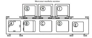
Mercosur markets version

Renault Kangoo - fuse box diagram - passenger compartment relay box
Renault Kangoo – fuse box diagram – passenger compartment relay box

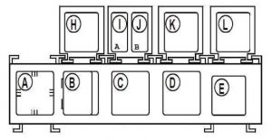
Right-hand drive version

Renault Kangoo - fuse box diagram - passenger compartment relay box
Renault Kangoo – fuse box diagram – passenger compartment relay box

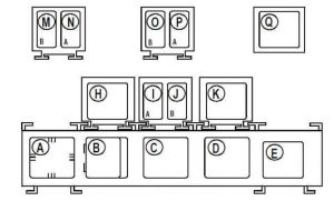
Sweden left-hand drive version

Renault Kangoo - fuse box diagram - passenger compartment relay box
Renault Kangoo – fuse box diagram – passenger compartment relay box

However, the relay board (M,N,O,P,Q) is located behind the instrument panel.

Number Description
A Buzzer: “Lights on” warning
B Unit: front timer
C Unit: central flasher
D
Mercosur: Relay: rear screen wiper
E Relay: heated rear screen
G Mercosur: Relay: + After ignition/+ Before ignition
H Relay: + After ignition/+ Before ignition relay
Mercosur: Relay: air conditioning
I Relay: front fog lights
Mercosur: Receiver: opening elements control
J Relay: fuel gauge (petrol/liquid petroleum gas)
K Relay: electric locks
L RHD: Receiver: opening elements control
M Sweden:Relay: daytime running lights dipped
N Sweden:Relay: daytime running lights side lights
O Sweden:Relay: main daytime lights (automatic transmission)
P Sweden:Relay: main daytime running lights (manual gearbox)
Q Receiver: opening elements control (Sweden) Receiver: Doors and windows control (Left-hand drive version in Europe/except Sweden/except Mercosur markets)

Engine compartment fuse box

Renault Kangoo - fuse box diagram - engine compartment
Renault Kangoo – fuse box diagram – engine compartment
Number Ampere rating [A] Description
F1 30 Injection
F8Q, F9Q790: Not in use
25 F9Q, K9K: Injection
F2 30 K7J, F8Q, F9Q790: Not in use
D4F712, D7F726, D7F744, F9Q, K4M, K9K: Fan unit
F3 5 Injection
F9Q, K9K: Not in use
F4 D4F712, D7F726, F9Q,K4M, K9K: Not in use
7,5 K7J: Automatic transmission module
10 D7F744: Liquid petroleum gas solenoid valve relay
15 F8Q: Engine functions
F5 15 K7J: Injection
D7F744: Injection/liquid petroleum gas
D7F726, K4M: Fan, ignition
F8Q: Not in use
F9Q, K9K: Engine functions
F6
70 F8Q, F9Q, K9K: Preheating unit
F7 50 D4F712, D7F726, K4M, K7J: Fan assembly
D7F744: Not in use
F8Q, F9Q, K9K: Engine functions
F8 60 Instrument panel
F9 60 Anti-lock braking system
80 K4M, F9Q790: Anti-lock braking system
F10 60 Instrument panel
F11 30 D7F744, F9Q790, K7J: Heater fan assembly
D4F712, D7F726, F8Q, F9Q, K9K: Air conditioning fan assembly
60 F9Q790, K4M, K7J: Air conditioning

Single or double fuses

Ampere rating [A] Description
80 F9Q, K9K: Power assisted steering pump assembly
70 F9Q, K9K: Thermoplungers
80 F9Q790:Injection
80 F9Q790: Fan unit

Engine compartment relay box (F8Q, F9Q, D4F, D7F744, F9Q, K4M752, K7J, K9K)

Renault Kangoo - fuse box diagram - engine compartment
Renault Kangoo – fuse box diagram – engine compartment
Number Description
A D7F744, F8Q:Not in use
F9Q, K9K: Thermoplungers
F9Q790 (4×4): Thermoplunger 2 and 3
K4M750: Fan assembly
B D7F744:Liquid petroleum gas solenoid valve
F8Q, F9Q, K9K:Not in use
F9Q790 (4×4): Fan assembly speed 2
K4M750: Fuel pump
C D7F744, F8Q, F9Q790 (4×4):Power assisted steering pump assembly
F9Q, K4M750, K9K:Not in use
D D7F744, F8Q, K4M750:Not in use
F9Q, K9K: Thermoplungers
F9Q790 (4×4): Thermoplunger 1
E D7F744, F8Q, F9Q, K9K:Not in use
F9Q790 (4×4): Speed fan 1
K4M750: Fan low-speed (air conditioning version)
F D4F, D7F744:Not in use
K7J: Ignition
F8Q:Fan assembly
F9Q, K9K: Power assisted steering pump assembly
K4M752: Not in use
G D7F744:Liquid petroleum gas fuel pump cut-off
F8Q, F9Q, K4M750, K9K:Not in use
F9Q790 (4×4): Fuel pump
H D4F, D7F744, F9Q, K7J, K4M752, K9K: Injection locking
F8Q:Altimetric correction
J D7F744, F8Q, F9Q, K9K:Not in use
F9Q790 (4×4): Diesel injection computer supply
K4M750: Injection locking
K D7F744, F8Q, F9Q, K9K:Fan low-speed (air conditioning version)
D4F, F9Q, K7J, K4M752, K9K: Fan assembly (air conditioning version)
L D4F, D7F744, K4M752, K7J: Fuel pump
F8Q:+ After ignition/+ Before ignition
F9Q, K9K: Fan assembly
M D4F, D7F744, K7J: Fan assembly
D4F, K7J: Fan low-speed (air conditioning version)
F8Q, F9Q:Diesel fuel heater
K4M752: Assembly low-speed relay (air conditioning version)
K9K:Not in use

Engine compartment relay box (D7D (Latin American markets))

Renault Kangoo - fuse box diagram - engine compartment
Renault Kangoo – fuse box diagram – engine compartment
Number Ampere rating [A] Description
F1 60 Fuse: instrument panel
F2 60 Fuse: instrument panel
F7 30 Fuse: engine protection
Relay
1 Injection
2 Injection
3
4 Air conditioning compressor control

Engine compartment relay box (D7F720 (Latin American markets))

Renault Kangoo - fuse box diagram - engine compartment
Renault Kangoo – fuse box diagram – engine compartment
Number Ampere rating [A] Description
F1 30 Fan unit
Relay
A Fan assembly
B Injection locking

Engine compartment relay box (D7D, K7M (Air conditioning; Mercosur markets))

Renault Kangoo - fuse box diagram - engine compartment
Renault Kangoo – fuse box diagram – engine compartment
Number Ampere rating [A] Description
F1 40 Instrument panel
F2 60 Instrument panel
F3 60 Instrument panel
F5 50 Engine protection
Relay
1 Injection
2 Injection
3 Fan assembly low-speed
4 Air conditioning compressor control
5 2-speed fan


Engine compartment relay box (K7M (Latin American markets))

Renault Kangoo - fuse box diagram - engine compartment
Renault Kangoo – fuse box diagram – engine compartment
Number Ampere rating [A] Description
F1 40 Instrument panel
F2 60 Instrument panel
F5 80 Engine protection
Relay
1 Injection
2 Injection
5 Fan assembly speed 2

Engine compartment relay box (F8Q (Latin American markets))

Renault Kangoo - fuse box diagram - engine compartment
Renault Kangoo – fuse box diagram – engine compartment
Number Ampere rating [A] Description
F1 40 Instrument panel
F2 60 Instrument panel
F3 60 Instrument panel
F4 50 Engine protection
F5 80 Engine protection
F6 70 Engine protection
Relay
1 Injection
2 Injection
3 Diesel fuel heater
4 Fan assembly
5 Fan assembly low-speed
6 Power assisted steering pump assembly
7 Air conditioning compressor control

WARNING: Terminal and harness assignments for individual connectors will vary depending on vehicle equipment level, model, and market.
Renault Espace (2002 – 2006) – fuse box diagram

Renault Espace (2002 – 2006) – fuse box diagram

Year of production: 2002, 2003, 2004, 2005, 2006

Fuse box on the dashboard

Renault Espace - fuse box diagram - dashboard
Renault Espace – fuse box diagram – dashboard
Number Ampere rating [A] Allocation
F1
F2 10 UCH supply – Card reader – Starter push button – Automatic parking brake
F3 10 Voice synthesiser – Xenon bulb beam adjustment – Instrument panels -Demisting jets – Headlight adjustment tumblewheel
F4 20 Reversing lights – Heating and air conditioning – Parking aid – + After ignition alarm signal – Switch control lighting – Rain sensor – Electrochrome door mirrors – Air conditioning compressor – Wiper motor signal
F5 15 Timed interior lighting
F6 20 Brake lights – Wiper stalk – Diagnostic socket – Child locking indicator – Rear electric lock indicator – Electric window switches lighting – cruise control -Hands-free kit connection
F7 15 Left-hand dipped beam headlight – Xenon bulb computer – Beam adjustment motor
F8 7,5 Right-hand side light
F9 15 Hazard warning lights and indicators
F10 10 Communication system – Radio – Driving position memory – Seat relay – Rear electric window relay feed
F11 30 Voice synthesiser – Instrument panel – Front fog lights – Air conditioning
F12 5 Airbags and pretensioners
F13 5 ABS computer – Electronic Stability Program
F14 15 Audible alarm (beeper)
F15 30 Driver’s side front window lift – Electric door mirrors
F16 30 Passenger’s electric window
F17 10 Rear fog lights
F18 10 Heated door mirrors
F19 15 Right-hand dipped headlight
F20 7,5 Left-hand side light – Lighting dimmer and glove box – Registration plate lighting -Cigarette lighter lighting – Switch lighting except doors and hazard warning lights – Parking brake control lighting
F21 30 Main beam headlights and rear wiper
F22 30 Central door locking
F23 15 Console accessories sockets
F24 15 Cigarette lighter
F25 10 Steering column lock – Heated rear screen relay supply
Renault Espace - fuse box diagram - dashboard
Renault Espace – fuse box diagram – dashboard
Track Description
RELAY
R2 Heated rear screen
R7 Front fog lights
R9 Windscreen wiper
R10 Windscreen wiper
R11 Rear screen – Reversing lights
R12 Door lock
R13 Door lock
R18 Timed interior lighting
R19 Relay plate
R21 Starting inhibition
R22 UCH – + after ignition
R23 Accessories, retro-fitted radio – Rear electric window
Shunt
SH1 Rear electric windows
SH2 Front electric windows
SH3 Daytime running lights
SH4 Daytime running lights

Central console

The consumer cut-out fuse is located in the central console, under the covering of the storage armrest.

Renault Espace - fuse box diagram - central console
Renault Espace – fuse box diagram – central console
Number Ampere rating [A] Descxription
F50 20 Consumer cut-off fuse: Diagnostic socket – Radio – Seat memory aid computer – Clock-exterior temperature assembly – Navigation aid computer – central communications unit – Alarm connection – Tyre pressure receiver


Renault Espace - fuse box diagram - dashboard
Renault Espace – fuse box diagram – dashboard


Number Ampere rating [A] Description
F32
F33
F34 15 Driver’s electric seat feed
F35 20 Driver’s and passenger’s heated seats
F36 20 Driver’s electric seat
F37 20 Passenger’s electric seat
Relay
R3 Seat supply
R4 Sidelight for daytime running lights
R5 Dipped beam headlights for daytime running lights
R6 Headlight washers pump
R7 Brake lights cut-off
Renault Espace - fuse box diagram - dashboard
Renault Espace – fuse box diagram – dashboard
Number Ampere rating [A] Description
F26 30 Caravan socket
F27 30 Sunroof
F28 30 Rear left-hand electric window
F29 30 Rear right-hand electric window
F30 5 Steering wheel angle sensor
F31 30 Curtain sunroof
Relay
R7 Air conditioning

Renault Espace - fuse box diagram - dashboard

Renault Espace – fuse box diagram – dashboard

Number Description
R20 Electric window

WARNING: Terminal and harness assignments for individual connectors will vary depending on vehicle equipment level, model, and market.
Renault Vel Satis – fuse box diagram

Renault Vel Satis – fuse box diagram

Year of production:

Fuse box on the dashboard

Renault Vel Satis - fuse box diagram - dashboard
Renault Vel Satis – fuse box diagram – dashboard
Number Ampere rating [A] Allocation
F1 20 Main beam headlights
F2 10 UCH supply – Card reader – Push button – Electric parking brake
F3 10 Voice synthesiser – Discharge bulb computer – Instrument panel – Heating jets – Headlight adjuster tumbewheel -Automatic speed limiter control
F4 20 Reversing lights – Heating and ventilation – Parking aid -Alarm + after ignition feed signal – Switch lighting – Rain sensor – Heated windscreen relay – Air conditioning compressor – Wiper motor signal – Autodimming rear-view mirror
F5 15 Timed interior lighting – Seat belt computer
F6 20 Brake lights – Wiper stalk – Diagnostic socket – Tyre pressure monitor display – Child locks indicator light – Rear electric lock indicator light – Electric window switch lighting – Cruise control switch
F7 15 Left-hand dipped headlight – Discharge bulb computer -Beam adjustment motor
F8 15 Right-hand side lights
F9 15 Hazard warning lights and indicators
F10 10 Communications system – Radio – Seat relays – Seat memory computer
F11 30 Voice synthesiser – Instrument panel – Front fog lights -Tailgate electric lock – Air conditioning
F12 5 Air bags and pretensioners
F13 5 ABS computer – Electronic braking distribution
F14 15 Horn
F15 30 Driver’s side front electric window – Electric door mirrors -Electric window multiplexing unit
F16 30 Passenger side front electric window – Electric window multiplexing unit
F17 10 Rear fog lights
F18 10 Heated door mirrors
F19 15 Right-hand dipped headlight
F20 7,5 Left-hand side lights – Dimmed lighting and glove box -Number plate lighting – Rear cigarette lighter and ashtrays lighting – Switch lighting except for doors and hazard warning lights – Parking brake control lighting
F21 30 Rear screen wiper
F22 30 Central door locking
F23 15 Console rear cigarette lighter – Car phone
F24 15 Cigarette lighter
F25 10 Steering lock – Heated rear screen relay stimulator
Renault Vel Satis - fuse box diagram - dashboard
Renault Vel Satis – fuse box diagram – dashboard
Track Description
RELAY
REL 2 Heated rear screen
REL 7 Front fog lights
REL 9 Windscreen wiper
REL 10 Windscreen wiper
REL 11 Rear wiper through reversing lights
REL 12 Central locking
REL 13 Central locking
REL 18 Timed interior lighting
REL 19 Accessories feed
REL 21 Starter inhibition
REL 22 Computer/+ after ignition feed
REL 23 Accessories, after-sales fitted radio/rear electric windows
Shunt
SH 1 Rear electric windows
SH 2 Front electric windows
SH 3 Daytime running lights (dipped beam headlights)
SH 4 Daytime running lights (side lights)

Central console

The consumer cut-out fuse is located in the central console, under the covering of the storage armrest.

Renault Vel Satis - fuse box diagram - central console
Renault Vel Satis – fuse box diagram – central console
Number Ampere rating [A] Descxription
F50 20 Consumer cut-out fuse: Diagnostic socket – Radio – Air conditioning control unit – Seat memory computer – Clock/external temperature/radio display unit – Navigation computer – Tyre pressure computer – Central communication unit – Alarm connection – Seat memory


Above UCH

This fuse box is located in the passenger compartment above the passenger compartment UCH on the driver’s side.

Renault Vel Satis - fuse box diagram - above UCH
Renault Vel Satis – fuse box diagram – above UCH
Number Ampere rating [A] Description
F26 30 Caravan socket
F27 30 Sunroof
F28 30 Rear left-hand electric window
F29 30 Rear right-hand electric window
F30 5 Steering wheel angle sensor
F31
Relay
R19 Electric window

Glove Compartment

This fuse box is located in the passenger compartment, behind the glove compartment.

Renault Vel Satis - fuse box diagram - glove compartment
Renault Vel Satis – fuse box diagram – glove compartment
Number Ampere rating [A] Description
F32
F33
F34 15 Driver’s electric seat supply
F35 20 Driver’s and passenger’s heated seats
F36 20 Driver’s electric seat
F37 20 Passenger’s electric seat
Relay
R3 Seat supply
R4 Daytime running lights monitor
R5 Daytime running lights code
R6 Headlight washers pump
R7 Brake lights cut-off

Fuse box in engine compartment

Renault Vel Satis - fuse box diagram - engine compartment
Renault Vel Satis – fuse box diagram – engine compartment
Number Ampere rating [A] Description
FM1 7,5 Automatic gearbox
FM2 10 Additional heater – Diesel heater control relay
FM3 30 Injection relay
FM4 5 DPO: Automatic transmission
15 SU1: Automatic transmission
FM5 30 Additional heater – Diesel heater relay
FM6 10 Injection computer – Diesel solenoid valve – Diesel heater
FM7
FM8
FM9 20 Fan unit low speed Air conditioning clutch and variable displacement actuator
FM10 30 ABS/ESP computer
FM11 30 Multifunction horn
FM12 70 Diesel pre-heating
FM13 70 Thermoplungers via relay R11
FM14 70 Thermoplunger via relay R1 and thermoplunger via relay R5
FM15 60 Fan unit high and low speed with air conditioning
FM16 40 Headlight washers – De-icing relay
FM17 40 ABS/ESP computer and ABS vacuum
FM18 70 Passenger compartment No. 1
FM19 70 Passenger compartment
FM20 60 Passenger compartment No. 3
FM21 60 Consumer cut-off fuse supply passenger compartment No. 2
FM22 80 Windscreen de-icing
FM23 60 Windscreen wiper and electric parking brake
Relay
R1 F4R – G9T – P9X: Additional heater 1
R2 F4R – G9T: Low speed fan unit with heating
V4Y – P9X: Fan unit with air conditioning
R3
R4
R5 F4R – G9T – P9X: Additional heater 3
R6 F4R – G9T: Fuel pump
V4Y: Injection
R7 F4R – G9T – P9X: Diesel heater
V4Y: Stepper motor safety
R8 Injection locking
R9 F4R – G9T: Low speed fan unit with air conditioning
V4Y – P9X: Fan unit with air conditioning
R10 Fan unit with air conditioning
R11 F4R – G9T – P9X: Additional heater 2

WARNING: Terminal and harness assignments for individual connectors will vary depending on vehicle equipment level, model, and market.
Renault Scenic (1996 – 2003) – fuse box diagram

Renault Scenic (1996 – 2003) – fuse box diagram

Year of production: 1996, 1997, 1998, 1999, 2000, 2001, 2002, 2003

Fuse box on the dashboard

Renault Scenic - fuse box diagram - dashboard
Renault Scenic – fuse box diagram – dashboard
Number Ampere rating [A] Allocation
F1 25 Rear left electric window riser
F2 5 Central door locking switch (Mexico)
F3 25 Rear right electric window riser
F4 15 Electric window wiper (only in 4×4 version)
F5 7,5 Electric rear-view mirror de-icing
F6 15 Consumer cut-out – Electric rear-view mirrors – Clock – Radio -Radio display – Navigation aid – Auto-regulated heating and ventilation – Tyre pressure detector- Electric aerial (E64)
F7 15 Horn
F8 5 Injection computer – Fan assembly relay – Diagnostic socket -Automatic gearbox computer – Instrument panel
F9 5 Rear fog light
F10 15 Front fog lights
F11 7,5 Left side lights
F12 10 Headlight washers
F13 7,5 Right-hand side lights
F14
F15
F16 5 ABS computer
F17 25 Passenger electric window winder
F18 15 Brake lights – Daytime running lights – Authorisation/inhibiting rear window winder control – Diagnostic socket – Instrument panel – Flashing warning lights on driving school control – + after ignition relay – Automatic gearbox performance/economy relay -Seatbelt and opening elements warning light – Heated windscreen relay
F19 15 UCH (+ after ignition reference and Screen wiper supply, park position and washer pump) – Reversing lights – Tyre pressure detector- Electric hood computer (E64)
F20
F21
F22 10 Left-hand main beam headlight
F23
F24 10 Right-hand main beam headlight
F25 20 Sunroof – Auto-regulated heating and ventilation
F26 10 Accessories sockets (2 sockets in 4×4)
F27 15 Heated seats
F28 20 Passenger compartment heating and ventilation system
F29 10 Left-hand dipped headlight
F30 15 Clock – Cigarette lighter – Daytime running lights function – Radio – Radio display – Navigation assistance
F31 10 Right-hand dipped headlight
F32 20 Engine cooling fan (Mercosur S. America)
F33
F 15 Indicators – Hazard lights
FB 5 Passenger compartment control unit supply
FC 20 Central door locking
FD 20 Windscreen wiper
FE 25 Driver’s one-touch electric window riser (from equipment 2)
FF 30 Rear screen de-icer – De-icing rear-view mirrors

Passenger Compartment Relay Box

Renault Scenic - fuse box diagram - passenger compartment relay box
Renault Scenic – fuse box diagram – passenger compartment relay box
Number Description
1 Relay + after ignition (sunroof and heated seats)
2 Electric rear windows authorisation
A Front fog lights
B Liquid petroleum gas fuel gauge
4X4 Version: Headlight washers

This box is located above the passenger compartment interconnections fuse board

Renault Scenic - fuse box diagram - passenger compartment relay box
Renault Scenic – fuse box diagram – passenger compartment relay box
Number Descxription
A Headlight washers
Mexico: Central door unlocking
B Daytime running lights code
Mexico: Central door locking
C Daytime running lights monitor
Mexico: Horn with alarm equipment
D Daytime running lights
Mexico: Not in use


Fuse box in engine compartment

Renault Scenic - fuse box diagram - engine compartment
Renault Scenic – fuse box diagram – engine compartment
Number Ampere rating [A] Description
F1 30 Fan and diesel heater
F2 30 Injection
F3 7,5 Air conditioning compressor
F4 3 Liquid petroleum gas
F5 7,5 Liquid petroleum gas
F6 7,5 Automatic gearbox computer – ignition
F7 7,5 Injection safety – diesel heater – air bag computer
F8 7,5 Liquid petroleum gas
F11 70 Pre-heating and thermoplunger
F12
F13
F14 40 Double speed fan and diesel heater
50
F15
F16 60 ABS computer
F17
F18 60 Heated windscreen
F19 40 Air conditioning fan assembly
F20 60 Dashboard supply
F21 60 Dashboard supply
F22 60 Dashboard supply
Relay
A Fuel pump
Diesel heater
B Injection locking
C Altimetric corrector
Thermoplunger no. 1
D Single speed fan assembly relay 100W-180W
Air conditioning compressor
F Automatic gearbox ignition
G
H
I Thermoplunger no. 2
J High speed fan assembly 340/550W
K Low speed fan assembly 340/550W
Diode
D9 Pilot diode Low Speed fan via air conditioning F8Q 790
D10 Free wheel air conditioning compressor

WARNING: Terminal and harness assignments for individual connectors will vary depending on vehicle equipment level, model, and market.
Renault Grand Scenic (2004 – 2009) – fuse box diagram

Renault Grand Scenic (2004 – 2009) – fuse box diagram

Year of production: 2004, 2005, 2006, 2007, 2008, 2009

Passenger compartment fuse box

This unit is located in the passenger compartment, in the lower left-hand section of the dashboard.

Renault Grand Scenic - fuse box diagram - passenger compartment
Renault Grand Scenic – fuse box diagram – passenger compartment
Number Ampere rating [A] Allocation
F1
F2
F3 10 Cigarette lighter
F4 10 Second row accessories socket (on keyless vehicle version)
F5
F6
F7 5 Passenger electric door mirror
F8 10 On keyless vehicle version: windscreen washer pump via steering column control – opening element warning sound unit
On vehicle with key version:: windscreen washer pump via steering column control – anti-theft tracker unit
F9
F10 10 Instrument panel (on keyless vehicle version)
F11
F12
F13
F14 25 Passenger electric window motor
F15 5 Brake light switch – ABS with ESP electric control unit – wheel speed electric control unit
F16 25 Rear right-hand electric window motor
F17 25 Rear left-hand electric window motor
F18 10 Passenger storage compartment light – left-hand boot light – front courtesy light – rear courtesy light – front right-hand courtesy mirror light – front left-hand courtesy mirror light – rain sensor – front passenger door light
F19 10 Combined clock/external temperature/radio telephone display – seat belt reminder module – CAN network interface unit – multimedia audio socket – anti-theft tracker unit (on keyless vehicle version)
F20 5 Automatic air conditioning control panel
F21 10 Fuel filler flap locking motor
F22
F23 20 Trailer socket switching module
F24 15 Via passenger compartment electric control unit: tailgate lock – right-hand luggage compartment lid light – left-hand luggage compartment lid light
F25
F26 10 Navigation assistance electric control unit
F27 10 Radio
F28
F29
F30 15 Via passenger compartment electric control unit:
Left-hand indicator lights: rear left-hand light – left-hand headlight – driver’s electric door mirror
Right-hand indicator lights: rear right-hand light – right-hand headlight – passenger electric door mirror
F31 10 Passenger compartment electric control unit supply
F32 30 Driver’s door multiplexed electric control unit
F33 25 Via passenger compartment electric control unit: rear right-hand door central locking – rear left-hand door central locking – passenger door central locking – fuel filler flap control – fuel filler flap locking motor
F34
F35 15 Combined clock/external temperature/radio telephone display – CAN network interface unit – instrument panel 
On vehicle with key version:
 – anti-theft tracker unit
F36 15 Diagnostic socket – alarm warning – alarm electric control unit – main electromagnetic horn supply via horn relay on fuse and relay board
F37 10 Via passenger compartment electric control unit:
Brake lights: rear left-hand light – rear right-hand light – high level brake light
F38
F39
F40 40 On keyless vehicle version: fan assembly power module – passenger compartment fan assembly 1 (via engine running + relay)
On vehicle with key version:: fan assembly power module – passenger compartment fan assembly 1
F41 25 Sunroof
F42 40 Via heated rear screen relay on passenger compartment fuse and relay box: heated rear screen – F7 fuse supply on passenger compartment fuse and relay box
Relay
A 70 Timed non-load shed + battery (no function power cut off during start phase)
B 70 On keyless vehicle version: Timed load shed + battery 1 (function power cut off during start phase)
On vehicle with key version:
 + Accessories feed
C 40 Heated rear screen
D 20 Horn

This unit is located in the passenger compartment, in the lower left-hand section of the dashboard, on the steering column side.

Renault Grand Scenic - fuse box diagram - passenger compartment
Renault Grand Scenic – fuse box diagram – passenger compartment 
Number Ampere rating [A] Allocation
C 70 Engine running 2 + relay for supplying the passenger compartment fan assembly, on the keyless vehicle version with manual air conditioning

Engine compartment fuse box

Renault Grand Scenic - fuse box diagram - engine compartment
Renault Grand Scenic – fuse box diagram – engine compartment
Number Ampere rating [A] Allocation
1 10 Right-hand side light – first row cigarette lighter- rear right-hand electric window control – rear left-hand electric window control – passenger electric window control – right-hand number plate light – left-hand number plate light – rear right-hand side light – radio – speed limiter and cruise control on/off switch – ESP on/off button – headlight adjustment rheostat switch – central door locking/hazard warning lights switch – parking distance control switch – automatic gearbox selector light – air conditioning control panel – right-hand side light – left-hand side light
2 10 Left-hand side light – rear left-hand side light
3 15 Headlight washer pump
4 20 Front left-hand fog light – front right-hand fog light
5 10 Left-hand headlight
6 10 Right-hand headlight
7 15 Diagnostic socket – shift pattern control – parking distance control electric control unit – heated rear screen relay control (on fuse and relay board – manual air conditioning control panel – rear view mirror – cruise control and speed limiter on/off control – left-hand headlight adjustment motor – right-hand headlight adjustment motor – discharge bulb electric control unit – anti-theft tracker unit
8 30 Anti-lock braking unit/electronic stability program electric control unit
9 30 Windscreen wiper motor
10 10 Airbag/pretensioner electric control unit – electric steering column lock (on keyless vehicle version)
11
12 7,5 Gearbox electric control unit – gearbox output speed sensor – gearbox output primary speed sensor – multifunction switch
13 25 K4M engine: injection electric control unit – petrol vapour absorber – injectors
K4M838 engine: injection electric control unit – variable camshaft – additional fuel pump relay control on engine fuse and relay box – motorised throttle valve – petrol vapour absorber
M4R engine: variable inlet camshaft – injectors – injectors – injection electric control unit – petrol vapour absorber
M4R752 and M4R753: variable inlet camshaft – injectors – injectors – injection electric control unit – petrol vapour absorber – additional fuel pump relay control on fuse and relay board – motorised throttle valve
F4R engine: injection electric control unit – injectors – turbocharger bearing coolant pump – petrol vapour absorber – wastegate solenoid valve – oil vapour recirculation hose reheater
14 15 K4M engine: downstream oxygen sensor – upstream oxygen sensor – camshaft inlet sensor engine
M4R engine: downstream oxygen sensor – upstream oxygen sensor
F4R engine: camshaft inlet sensor – variable inlet camshaft – downstream oxygen sensor – upstream oxygen sensor
15 20 Gearbox electric control unit
16 5 Brake light switch – passenger compartment electric control unit – electric power-assisted steering system
17 10 Manual gearbox TDC sensor and reversing lights – reversing light via protection and switching unit and via relay on fuse and relay board on automatic gearbox version
18 15 Steering column lock via passenger compartment electric control unit (on keyless vehicle version)
19 25 Starter
20
21 20 M4R engine: fuse fuel gauge and pump – cylinder 1 pencil coil – cylinder 2 pencil coil – cylinder 3 pencil coil – cylinder 4 pencil coil –
On K4M and F4R engine: fuse fuel gauge and pump – cylinder 3 pencil coil – cylinder 4 pencil coil
22 10 Air conditioning clutch
23 5 Fuse injection ECU
24 20 Left-hand headlight
25 20 Right-hand headlight

Location: This unit is located behind the battery.

Renault Grand Scenic - fuse box diagram - engine compartment
Renault Grand Scenic – fuse box diagram – engine compartment
Number Ampere rating [A] Allocation
F1
F2 80 Supply to fuses F37 and F38 on passenger compartment fuse and relay box – supply to fuses F3, F4, F5, F6, F8, F11 and F40 on passenger compartment fuse and relay box via relay on passenger compartment fuse and relay box
F3 80 Supply to fuses F9, F12, F41 and F42 on passenger compartment fuse and relay box
F4 80 Protection and switching unit – supply to fuses F23 and F24 on passenger compartment fuse and relay box  – supply to fuses F1, F2, F14, F15, F16, F17, F18, F19, F20, F21 and F22 on passenger compartment fuse and relay box via relay on passenger compartment fuse and relay box
F5
F6 50 ABS computer with ESP

This unit is located in the engine interconnection unit, below the Protection and Switching Unit.

Renault Grand Scenic - fuse box diagram - engine compartment
Renault Grand Scenic – fuse box diagram – engine compartment
Number Ampere rating [A] Allocation
F1
F2
F3
F4
F5 60 Fan assembly via high speed fan assembly relay
F6 20 Additional fuel pump via additional fuel pump relay on engine fuse and relay box on K4M864, M4R752 and M4R753 engines
F7
F8 30 Fan assembly through low speed fan assembly resistor via protection and switching unit – fan assembly relay control
F9
Relay
A
B 20 Additional fuel pump for K4M864, M4R752 and M4R753 engines
C 20 Reversing light on automatic gearbox version
D

Location: This unit is located behind the battery.

Renault Grand Scenic - fuse box diagram - engine compartment
Renault Grand Scenic – fuse box diagram – engine compartment
Number Ampere rating [A] Allocation
F1 300 M4R714, M4R751, M4R752, M4R753: Starting protected + battery
190 K4M838, K4M864, F4R872: Starting protected + battery
F2 50 Supply to fuses F30, F31, F32, F33, F34, F35 and F36 on passenger compartment fuse and relay box
F3 80 Supply to fuses F10, F26 and F27 on passenger compartment fuse and relay box – protection and switching unit
F4 300 M4R714, M4R751, M4R752, M4R753: Supply to fuses F1, F2, F3, F4, F5, F6, F8 and F9 on engine fuse and relay box – supply to fuses on fuse board – alternator
K4M838, K4M864, F4R872: Supply to fuses F1, F2, F3, F4, F5, F6, F8 and F9 on engine fuse and relay box – supply to fuses on fuse board – alternator
F5 80 Electric power-assisted steering system
F6 35 Protection and switching unit
F7 5 Protection and switching unit
1 5 Protected + battery > protection and switching unit
2
3

This unit is located next to the fan assembly

Renault Grand Scenic - fuse box diagram - engine compartment
Renault Grand Scenic – fuse box diagram – engine compartment
Number Ampere rating [A] Allocation
234 70 Engine cooling fan assembly

WARNING: Terminal and harness assignments for individual connectors will vary depending on vehicle equipment level, model, and market.
Renault Duster – fuse box diagram

Renault Duster – fuse box diagram

Year of production:

Passenger Compartment Fuse Box

Dacia Duster - fuse box diagram - passenger compartment
Renault Duster – fuse box diagram – passenger compartment
Dacia Duster - fuse box diagram - passenger compartment
Renault Duster – fuse box diagram – passenger compartment
Number Ampere rating [A] Allocation
F1 20 Windscreen wiper motor – screen wash/wipe combination switch – UCH
F2 5 Instrument panel – fuel pump relay control on board – injection computer
F3 10 Brake light switch
F4 10 UCH – diagnostic socket – transponder unit – shift pattern control – anti-theft tracker unit
F5 5 Automatic gearbox electric control unit – starter relay control – front/rear torque distribution electric control unit
F6
F7
F8
F9 10 Left-hand dipped beam headlight – instrument panel
F10 10 Right-hand dipped headlight
F11 10 Left-hand main beam headlight – instrument panel
F12 10 Right-hand main beam headlight
F13 30 Driver’s dual rear electric window control – child safety relay control
F14 30 Driver’s dual front electric window control
F15 10 Anti-lock braking system ECU
F16 15 Radio
F17 15 Main electromagnetic horn – secondary electromagnetic horn
F18 10 Rear left-hand side light – front left-hand side light
F19 10 Rear right-hand side light – passenger storage compartment light – instrument panel – UCH – hazard warning lights control – air conditioning control panel – radio – central door locking switch – first row cigarette lighter – 4×4 mode control – right-hand number plate light – left-hand number plate light – front right-hand side light – traction control switch – heated rear screen control – parking proximity sensor switch
F20 7,5 Rear fog light
F21 5 Instrument panel
F22
F23 15 Fuse on alarm version: Supply to horns via horn relay on board
F24
F25
F26 5 Airbag and pretensioner control unit
F27 20 Rear screen wiper motor – wash/wipe combination switch – reversing lights switch – neutral and reversing sensor on manual gearbox – automatic gearbox module – parking proximity sensor electronic control unit
F28 15 Consumer cut-out – instrument panel – radio – UCH
F29 15 UCH – diagnostic socket – anti-theft tracker unit
F30 20 UCH
F31 15 Supply to front right-hand and left-hand fog light via front fog relay on board – instrument panel indicator light
F32 30 heated rear screen switch
F33
F34 15 Front-rear torque distribution electric control unit
F35
F36 30 Cold air blower unit supply via cold air blower unit relay and air conditioning control panel
F37 5 Right-hand and left-hand electric door mirror supply via electric door mirror control
F38 15 Radio – first row cigarette lighter
F39 10 Cold air blower unit relay control

This relay is located in the passenger compartment, in the lower left-hand section of the dashboard

Dacia Duster - fuse box diagram - passenger compartment
Renault Duster – fuse box diagram – passenger compartment
Number Ampere rating [A] Description
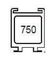
750 40 Child safety

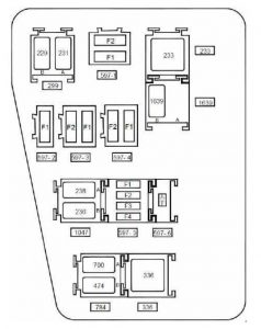
Engine compartment fuse box (K4M690-K4M694)

Dacia Duster - fuse box diagram - engine compartment (K4M690 - K4M694)
Renault Duster – fuse box diagram – engine compartment (K4M690 – K4M694)
Number Ampere rating [A] Description
Fuse board 597- 1
F1 50 Anti-lock braking system electric control unit on versions without electronic stability program
F2 25 Anti-lock braking system electric control unit on versions without electronic stability program
Fuse board 597- 2
F1 40 Fuse on air conditioning version: Cooling fan assembly supply via fan assembly high-speed relay or via fan assembly low speed relay on relay board and fan assembly resistor – air conditioning clutch supply via air conditioning clutch relay on board
Fuse board 597- 3
F1 60 Ignition switch – monolever – supply to fuse F23 on passenger compartment fuse box
F2 60 Monolever supply – supply to fuses F29 and F36 on passenger compartment fuse box
Fuse board 597- 4
F1
F2 25 F34 fuse supply on passenger compartment fuse box on 4×4 version (four wheel drive)
Fuse board 597- 5
F1 30 Fuse on standard heating version: cooling fan assembly supply via low speed fan assembly relay on relay board
F2 25 Injection locking relay control and supply on relay board – fuel pump relay supply on relay board
F3
F4
Diode 597- 6 support plate
Diode Air conditioning clutch
Relay board 299
A 20 Front fog lights
B 20 Horn
Unit relay 233
233 40 Cold air blower
Relay board 1047
A 20 Injection locking
B 20 Fuel pump
Relay board 784
A 20 Low speed fan assembly
B 20 Air conditioning clutch
Unit relay 336
336 40 High speed fan assembly
Relay 1639 board on FLEXFUEL version
A Not in use
B 20 Additional fuel pump

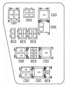
Engine compartment fuse box (F4R400-F4R402-F4R403-F4R404-F4R405-F4R408)

Dacia Duster - fuse box diagram- engine compartment fuse box (F4R400-F4R402-F4R403-F4R404-F4R405-F4R408)
Renault Duster – fuse box diagram- engine compartment fuse box (F4R400-F4R402-F4R403-F4R404-F4R405-F4R408)
Number Ampere rating [A] Description
Fuse board 597- 1
F1 50 Anti-lock braking system electric control unit on versions without electronic stability program
F2 25 Anti-lock braking system electric control unit on versions without electronic stability program
Fuse board 597- 2
F1 40 Fuse on air conditioning version: cooling fan assembly supply via high speed fan assembly relay or via low speed fan assembly relay on relay board and fan assembly resistor
Fuse board 597- 3
F1 60 Ignition switch – monolever – supply to fuse F23 on passenger compartment fuse box
F2 60 Monolever supply – supply to fuses F29 and F36 on passenger compartment fuse box
Fuse board 597- 4
F1
F2 25 F34 fuse supply on passenger compartment fuse box on 4×4 version (four wheel drive)
Fuse board 597- 5
F1 15 Fuse on air conditioning version: Air conditioning clutch supply via air conditioning clutch relay on board
F2 25 Injection locking relay control and supply on relay board – fuel pump relay supply on relay board
F3
F4 15 Automatic gearbox electric control unit (119) with 4-speed automatic gearbox on F4R403 and F4R405 engines
Diode 597- 6 support plate
Diode Air conditioning clutch
Relay board 299
A 20 Front fog lights
B 20 Horn
Unit relay 233
233 40 Cold air blower
Relay board 1047
A 20 Injection locking
B 20 Fuel pump
Relay board 784
A 20 Low speed fan assembly
B 20 Air conditioning clutch
Unit relay 336
336 40 High speed fan assembly
Unit relay 232 on automatic gearbox version
22 40 Starter
Relay 1639 board on FLEXFUEL version
A
B 20 Additional fuel pump


WARNING: Terminal and harness assignments for individual connectors will vary depending on vehicle equipment level, model, and market.