Dacia Duster (2009 – 2013) – fuse box diagram

Dacia Duster – fuse box diagram

Year of production: 2009, 2010 2011, 2012, 2013

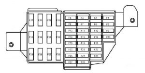
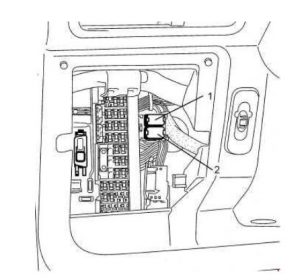
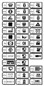
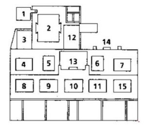
Passenger Compartment Fuse Box
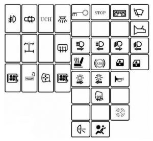
Dacia Duster - fuse box diagram - passenger compartment
Dacia Duster – fuse box diagram – passenger compartment
Dacia Duster - fuse box diagram - passenger compartment
Dacia Duster – fuse box diagram – passenger compartment
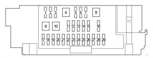
Number Ampere rating [A] Allocation
F1 20 Windscreen wiper motor – screen wash/wipe combination switch – UCH
F2 5 Instrument panel – fuel pump relay control on board – injection computer
F3 10 Brake light switch
F4 10 UCH – diagnostic socket – transponder unit – shift pattern control – anti-theft tracker unit
F5 5 Automatic gearbox electric control unit – starter relay control – front/rear torque distribution electric control unit
F6
F7
F8
F9 10 Left-hand dipped beam headlight – instrument panel
F10 10 Right-hand dipped headlight
F11 10 Left-hand main beam headlight – instrument panel
F12 10 Right-hand main beam headlight
F13 30 Driver’s dual rear electric window control – child safety relay control
F14 30 Driver’s dual front electric window control
F15 10 Anti-lock braking system ECU
F16 15 Radio
F17 15 Main electromagnetic horn – secondary electromagnetic horn
F18 10 Rear left-hand side light – front left-hand side light
F19 10 Rear right-hand side light – passenger storage compartment light – instrument panel – UCH – hazard warning lights control – air conditioning control panel – radio – central door locking switch – first row cigarette lighter – 4×4 mode control – right-hand number plate light – left-hand number plate light – front right-hand side light – traction control switch – heated rear screen control – parking proximity sensor switch
F20 7,5 Rear fog light
F21 5 Instrument panel
F22
F23 15 Fuse on alarm version: Supply to horns via horn relay on board
F24
F25
F26 5 Airbag and pretensioner control unit
F27 20 Rear screen wiper motor – wash/wipe combination switch – reversing lights switch – neutral and reversing sensor on manual gearbox – automatic gearbox module – parking proximity sensor electronic control unit
F28 15 Consumer cut-out – instrument panel – radio – UCH
F29 15 UCH – diagnostic socket – anti-theft tracker unit
F30 20 UCH
F31 15 Supply to front right-hand and left-hand fog light via front fog relay on board – instrument panel indicator light
F32 30 heated rear screen switch
F33
F34 15 Front-rear torque distribution electric control unit
F35
F36 30 Cold air blower unit supply via cold air blower unit relay and air conditioning control panel
F37 5 Right-hand and left-hand electric door mirror supply via electric door mirror control
F38 15 Radio – first row cigarette lighter
F39 10 Cold air blower unit relay control

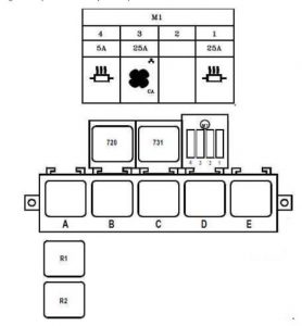
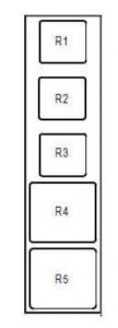
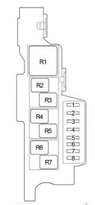
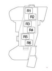
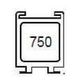
This relay is located in the passenger compartment, in the lower left-hand section of the dashboard
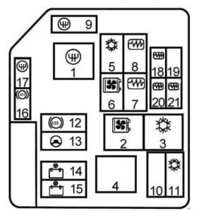
Dacia Duster - fuse box diagram - passenger compartment
Dacia Duster – fuse box diagram – passenger compartment
Number Ampere rating [A] Description
750 40 Child safety

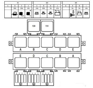
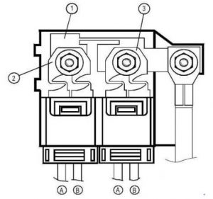
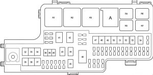
Engine compartment fuse box (K4M690-K4M694)
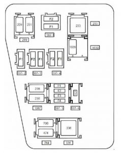
Dacia Duster - fuse box diagram - engine compartment (K4M690 - K4M694)
Dacia Duster – fuse box diagram – engine compartment (K4M690 – K4M694)
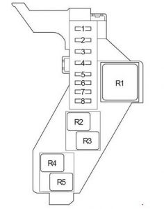
Number Ampere rating [A] Description
Fuse board 597- 1
F1 50 Anti-lock braking system electric control unit on versions without electronic stability program
F2 25 Anti-lock braking system electric control unit on versions without electronic stability program
Fuse board 597- 2
F1 40 Fuse on air conditioning version: Cooling fan assembly supply via fan assembly high-speed relay or via fan assembly low speed relay on relay board and fan assembly resistor – air conditioning clutch supply via air conditioning clutch relay on board
Fuse board 597- 3
F1 60 Ignition switch – monolever – supply to fuse F23 on passenger compartment fuse box
F2 60 Monolever supply – supply to fuses F29 and F36 on passenger compartment fuse box
Fuse board 597- 4
F1
F2 25 F34 fuse supply on passenger compartment fuse box on 4×4 version (four wheel drive)
Fuse board 597- 5
F1 30 Fuse on standard heating version: cooling fan assembly supply via low speed fan assembly relay on relay board
F2 25 Injection locking relay control and supply on relay board – fuel pump relay supply on relay board
F3
F4
Diode 597- 6 support plate
Diode Air conditioning clutch
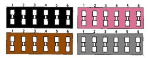
Relay board 299
A 20 Front fog lights
B 20 Horn
Unit relay 233
233 40 Cold air blower
Relay board 1047
A 20 Injection locking
B 20 Fuel pump
Relay board 784
A 20 Low speed fan assembly
B 20 Air conditioning clutch
Unit relay 336
336 40 High speed fan assembly
Relay 1639 board on FLEXFUEL version
A Not in use
B 20 Additional fuel pump

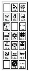
Engine compartment fuse box (F4R400-F4R402-F4R403-F4R404-F4R405-F4R408)
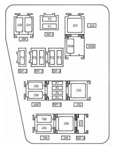
Dacia Duster - fuse box diagram- engine compartment fuse box (F4R400-F4R402-F4R403-F4R404-F4R405-F4R408)
Dacia Duster – fuse box diagram- engine compartment fuse box (F4R400-F4R402-F4R403-F4R404-F4R405-F4R408)
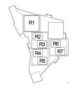
Number Ampere rating [A] Description
Fuse board 597- 1
F1 50 Anti-lock braking system electric control unit on versions without electronic stability program
F2 25 Anti-lock braking system electric control unit on versions without electronic stability program
Fuse board 597- 2
F1 40 Fuse on air conditioning version: cooling fan assembly supply via high speed fan assembly relay or via low speed fan assembly relay on relay board and fan assembly resistor
Fuse board 597- 3
F1 60 Ignition switch – monolever – supply to fuse F23 on passenger compartment fuse box
F2 60 Monolever supply – supply to fuses F29 and F36 on passenger compartment fuse box
Fuse board 597- 4
F1
F2 25 F34 fuse supply on passenger compartment fuse box on 4×4 version (four wheel drive)
Fuse board 597- 5
F1 15 Fuse on air conditioning version: Air conditioning clutch supply via air conditioning clutch relay on board
F2 25 Injection locking relay control and supply on relay board – fuel pump relay supply on relay board
F3
F4 15 Automatic gearbox electric control unit (119) with 4-speed automatic gearbox on F4R403 and F4R405 engines
Diode 597- 6 support plate
Diode Air conditioning clutch
Relay board 299
A 20 Front fog lights
B 20 Horn
Unit relay 233
233 40 Cold air blower
Relay board 1047
A 20 Injection locking
B 20 Fuel pump
Relay board 784
A 20 Low speed fan assembly
B 20 Air conditioning clutch
Unit relay 336
336 40 High speed fan assembly
Unit relay 232 on automatic gearbox version
22 40 Starter
Relay 1639 board on FLEXFUEL version
A
B 20 Additional fuel pump


WARNING: Terminal and harness assignments for individual connectors will vary depending on vehicle equipment level, model, and market.

Renault Megane (2003 – 2009) – fuse box diagram

Renault Megane (2003 – 2009) – fuse box diagram

Year of production: 2003, 2004, 2005, 2006, 2007, 2008, 2009

Passenger Compartment Fuse Box

Renault Megane - fuse box diagram - passenger compartment
Renault Megane – fuse box diagram – passenger compartment
Renault Megane - fuse box diagram - passenger compartment
Renault Megane – fuse box diagram – passenger compartment
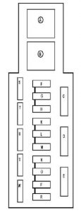
Number Ampere rating [A] Allocation
C 30 Passenger compartment ventilation
D 40 Rear electric windows or electric windows relay
30 Rear electric windows or electric windows relay
E 20 K84 and L84: Electric sunroof
40 E84: Sunroof hydraulic unit relay
F 10 ABS computer or Electronic Stability Program
G 15 Radio – multifunction display – headlight washer pump relay – headlight washer pump relay 2 – first row cigarette lighter (on K84 and L84) – driver and passenger heated seat – bi-directional windscreen and rear screen washer pump – diesel heater relay – air conditioning control panel – air conditioning control unit – rigid retractable roof computer (on E84) – return sensor (on E84) – interior rear-view mirror (on E84) – Central communication unit – Central alarm unit
H 15 Brake lights
K
L 25 Driver’s electric window
M 25 Passenger electric window – electric windows relay
N 20 Consumer cut-out:
Instrument panel
Radio
Multifunction display
Electric door mirror switch
Alarm control unit
O 15 Main electromagnetic horn – diagnostic socket – headlight washer pump relay – headlight washer pump relay 2 – rigid retractable roof computer (on E84) – driving school monitor control
P 15 Rear screen wiper motor (on K84)
R 20 UCH air conditioning control unit – accessories relay 1
S 3 K84 and L84: Passenger compartment temperature sensor fan – interior rear-view mirror – light and rain sensor
T 20 Passenger and driver’s heated seat
U 20 Door electric locking or dead-locking
V 15 E84: Cigarette lighter
W 7,5 Passenger and driver’s heated door mirrors
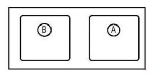
RELAY
A 40 Electric window
B 40 Accessories 1

Passenger Compartment Relay Box

This unit is located under the dashboard on the left-hand side of the passenger compartment fan assembly.

Renault Megane - fuse box diagram - passenger compartment (relay box)
Renault Megane – fuse box diagram – passenger compartment (relay box)
Number Ampere rating [A] Description
A 40 330W auxiliary heating 1
B 70 660W auxiliary heating 2


This relay is located on the accelerator pedal mounting.

Renault Megane - fuse box diagram - passenger compartment (relay box)
Renault Megane – fuse box diagram – passenger compartment (relay box)
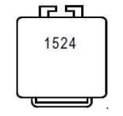
Number Ampere rating [A] Description
1524 40 Brake lights lighting controlled by the ESP ECU

Engine Compartment Fuse Box

Renault Megane - fuse box diagram - engine compartment
Renault Megane – fuse box diagram – engine compartment
Number Ampere rating [A] Description
F3 25 Starter motor solenoid
F4 10 Air conditioning compressor clutch
F5A 15 Steering column electric lock
F5C 10 Reversing lights
F5D 5 Injection computer + after ignition feed – steering column electric lock
F5E 5 Airbag + after ignition feed and electric power assisted steering
F5F 7,5 Passenger compartment + after ignition: gear lever display – shift pattern control – cruise control/speed limiter on/off control – driving school monitor control – passenger compartment fuse and relay box – auxiliary heater relay 1 – auxiliary heater relay 2 – diagnostic socket – hands-free telephone radio microphone – rain and light sensor (on E84) – passenger compartment temperature sensor (on E84)
15 Passenger compartment + ignition feed: gear selector lever display – shift pattern control switch – cruise control stop/start control – driving school instructor’s control unit – passenger compartment fuse and relay box – additional heater relay 1 – additional heater relay 2 – diagnostic socket – car phone hands-free microphone
F5H 5 Automatic gear box + after ignition feed
F5G 10 LPG injection computer + after ignition feed
F6 30 Heated rear screen
F7A 7,5 Right-hand side light – cruise control stop/start control – ESP stop/start button – gear selector lever display – left-hand heated seat control – right-hand heated seat control – rigid roof switch – windscreen simultaneous control – LPG or petrol selector switch
F7B 7,5 Left-hand side lights – cigarette lighter – hazard warning lights and door locking switch – headlight adjustment rheostat switch – air conditioning control panel – radio – multifunction display – CCU – CD changer – driver’s dual front electric window control – electric door mirror control – rear electric window locking control – driver’s dual rear window control – passenger electric window control – rear right-hand electric window control – rear left-hand electric window control
F8A 10 Right-hand main beam headlights
F8B 10 Left-hand main beam headlights
F8C 10 Right-hand dipped beam headlight – rear height sensor – front height sensor – headlight adjustment rheostat switch – right-hand headlight adjustment motor
F8D 10 Left-hand dipped beam headlight – left-hand headlight adjustment motor
15 Left-hand dipped beam headlight – left-hand headlight adjustment motor
F9 25 Windscreen wiper motor
F10 20 Front left and right-hand fog lights
F11 40 Engine cooling fan unit
F13 25 ABS computer or Electronic Stability Program
F15 20 Automatic gearbox + battery feed or gas solenoid valve relay + battery feed
F16 10

This unit is located in the engine interconnection unit, below the Protection and Commutation Unit.

Renault Megane - fuse box diagram - engine compartment
Renault Megane – fuse box diagram – engine compartment
Number Ampere rating [A] Description
F1 40 K9K724: 460 Watt engine cooling fan
60 K9K732: 550 Watt engine cooling fan
F2 70 Preheating unit
F3 20 F9Q: Diesel filter heater relay
F4 70 Passenger compartment fuse and relay box
F5 50 ABS computer
F6 70 Electric power assisted steering system or Additional heater relay 2
F7 40 Auxiliary heater relay 1
F8 60 Passenger compartment fuse and relay box
F9 70 Auxiliary heater relay 2 or Electric power-assisted steering system


This unit is located on the positive battery terminal.

Renault Megane - fuse box diagram - engine compartment
Renault Megane – fuse box diagram – engine compartment
Number Ampere rating [A] Description
F1 30 Passenger compartment fuse and relay box protected + battery feed – UCH
F2 350 Petrol engines: + protected starter battery – alternator – power feed fuse board – switching and protection unit
F2 400 Diesel engines: + protected starter battery – alternator – power feed fuse board – switching and protection unit
F3 30 + engine function protected battery via protection and switching unit


This unit is located in the engine interconnection unit, below the Protection and Switching Unit

Renault Megane - fuse box diagram - engine compartment
Renault Megane – fuse box diagram – engine compartment
Number Ampere rating [A] Description
A 25 Headlight washer pump
B 25 Headlight washer pump 2

F9Q

This unit is located in the engine interconnection unit, below the Protection and Switching Unit.

Renault Megane - fuse box diagram - F9Q
Renault Megane – fuse box diagram – F9Q
Number Ampere rating [A] Description
A 20 F9Q: Diesel heater
B 20 F9Q814: Electric coolant pump
Relay
983 50 F9Q814: Injection control unit feed

K9K

This unit is located in the engine interconnection unit, below the Protection and Switching Unit.

Renault Megane - fuse box diagram - K9K
Renault Megane – fuse box diagram – K9K
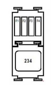
Number Ampere rating [A] Description
F1
F2
F3
F4 15 + feed for main injector relay (air flowmeter feed protection)
Relay
234 40 K9K724: 460 Watt engine cooling fan (with air conditioning)
50 K9K732: 550 Watt engine cooling fan (with air conditioning)


K4M

This unit is located in the engine interconnection unit, below the Protection and Switching Unit

Renault Megane - fuse box diagram - K4M
Renault Megane – fuse box diagram – K4M
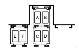
Number Ampere rating [A] Description
A 20 Fuel pump
B 20 Fuel pump cut-off for LPG
C 20 LPG solenoid valve
D 20 LPG tank
E 20 Gas expansion valve solenoid valve
F


WARNING: Terminal and harness assignments for individual connectors will vary depending on vehicle equipment level, model, and market.
Renault Twingo (2000 – 2004) – fuse box diagram

Renault Twingo (2000 – 2004) – fuse box diagram

Year of production: 2000, 2001, 2002, 2003, 2004

Passenger Compartment Fuse Box

Renault Twingo - fuse box diagram - passenger compartment
Renault Twingo – fuse box diagram – passenger compartment
Fuse Ampere rating [A] Allocation
1 20 Engine connection unit
2 15 Rear screen wiper, Reversing lights, Windscreen/rear window washer pump
3 10 Pretensioners, Air bag, Engine immobiliser
4 10 Radio
5 20 Heated rear window
6 20 Injection
7 20 Heating/air conditioning fan unit
8 15 Brake lights
9 15 Windscreen wiper
10 10 Rear fog lights
11 10 Anti-lock braking system
12 25 Cigarette lighter, Sunroof
13 15 Left-hand main beam headlight
14 15 Right-hand main beam headlight
15 30 Electric window winders
16 15 Left-hand dipped headlight
17 15 Right-hand dipped headlight
18 10 Left side lights
19 10 Right-hand side lights
20 25 Indicators, Rear fog light, UCH
21 10 Horn, Engine immobiliser
22 10 Interior lighting/Short circuit, Diagnostic socket
23 10 Electrical power-assisted steering
24
25 15 Electric door locking, Electric rear-view mirrors
26
27 2 Sequential gearbox
Renault Twingo - fuse box diagram - passenger compartment
Renault Twingo – fuse box diagram – passenger compartment
Number Protected components
1
2 Front fog lights relay


Passenger Compartment Relay Box

This board is located under the dashboard beside the pedals..

Renault Twingo - fuse box diagram - passenger compartment (relay box)
Renault Twingo – fuse box diagram – passenger compartment (relay box)
Number Protected components
A Sequential transmission
B
C Sequential gearbox starting
D
E

Engine Compartment Fuse Box

Renault Twingo - fuse box diagram - engine compartment
Renault Twingo – fuse box diagram – engine compartment
Number Ampere rating [A] Protected components
RELAY
1 50 Sequential gearbox
2 50 Fan assembly (with air conditioning)
3 25 Low speed fan (with air conditioning)
4
5 25 Air conditioning compressor
6 25 Fan assembly (except air conditioning)
7 25 Injection locking
8 25 Fuel pump
FUSES
9 30 Sequential gearbox
10
11 40 Air conditioning
12 30 Anti-lock braking system
13 30 Electrical power-assisted steering
14 60 Passenger compartment
15 60 Passenger compartment
16 20 Sequential gearbox
17 30 Anti-lock braking system
18 10 Injection
19
20 25 Injection
21 15 Injection

WARNING: Terminal and harness assignments for individual connectors will vary depending on vehicle equipment level, model, and market.
Renault Midlum (2005) – fuse box diagram

Renault Midlum (2005) – fuse box diagram

Year of production: 2005

Fuse box

Renault Midlum - fuse box diagram
Renault Midlum – fuse box diagram
Fuse Ampere riting [A] Description
1 15 Trailer socket 7-pin (“ABS”)
Trailer socket, 7-pin type 24 S
Stop lights relay
2 10 Front side/parking lights
RH rear side/parking lights
Registration plate RH light
Voltage dropper (headlamps adjustment)
3 10 Marker lights
LH rear side/parking lights
Registration plate LH light
Dashboard instruments lighting
Switch lighting
4 10 Trailer side/parking lights
5 10 Available power supply (lighting)
7 10 Jake brake electrovalves
Engine stop control
Fuel filter clogging
“EUP” ECU
8 15 Fog light(s)
Fog driving lights
12 10 RH dipped beam headlight
13 10 LH dipped beam headlight
14 15 RH main beam headlight
LH main beam headlight
Long beam driving lights
16 10 Dashboard warning lights and instruments power supply
Electric or hydraulic retarder control
Exhaust brake electrovalve
“ABS-ASR” ECU
17 20 Heated driver’s seat
Voltage dropper (12V socket)
Voltage dropper (telecommunications)
18 15 Fan coil heaters
19 25 Fuel filter preheater
20 20 Revolving beacons
Roof air vent motor
21 10 Power supply (after master switch)
22 20 Independent heater AT 2000
23 10 Driver’s overhead light
Passenger(s) overhead light
24 20 Driver’s window winder motor
Passenger’s window winder motor
25 5 Tachograph clock
26 15 Horn
27 10 Stop lights
28 15 “ABS” ECU
Electric retarder cut-off relay
29 10 Defrosting rearview mirrors
Windscreen defrosting time-delay relay
30 10 Cigar lighter
Radio
31 20 Socket 24 Volts
Voltage dropper (extra 12V socket)
32 20 Windscreen wiper speed controller
Windscreen washer pump
Headlamps washer pump
Windscreen wiper motor
33 20 Diagnostics socket
Suspension ECU
34 15 Radio tuner memory power supply
Independent heater AT 2000
Flasher unit
35
36 20 Trailer socket 7-pin (“ABS”)
37 15 LH door lock electric striker
RH door lock electric striker
External rearview mirrors swivelling control
Step light
LH rear door overhead light
RH rear door overhead light
38 25 “EUP” ECU
39 10 Automatic gearbox ECU
42 10 Automatic gearbox ECU power supply
43 10 Loading floodlight (tractor)
Trailer socket, 7-pin type 24 S
Bodybuilder equipment control
Gate valves illumination control
Exhaust brake cut-off relay
45 10 Doors central locking box
46 15 Fuel preheater relay
Reversing lamp(s)
Reversing buzzer
Rearview mirrors defrosting relay
47 10 Suspension ECU
Suspension remote control box
50
52 10 Windscreen wiper time-delay relay
57 15 “EUP” VECU ECU
Electronic tachograph
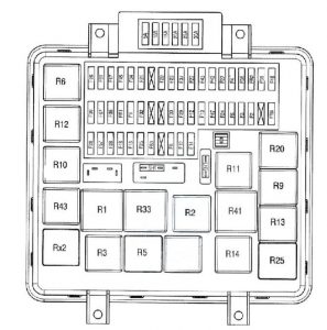
Relay
R1 After ignition power supply relay No. 1
R2 Power after ignition relay
R3 Windscreen wiper safety relay
R5 Side / parking lights relay
R6 Comfort accessories relay
R9 Fog lights relay
R10 Fog driving lights relay
R11 Dipped beam headlights relay
R12 Main beam headlights relay
R13 Long range driving lights
R14 Stop lights relay
R18 Electric retarder cut-off relay
R20 Rearview mirrors and windscreen defrosting relay
R23 Revolving beacon(s) relay
R25 Windscreen wiper relay
R33 Starting relay
R41 Fuel preheater relay
R43 “VECU / EECU” ECU power supply relay

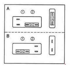
Shunts

Configuration A: With ADR and with daytime lights.
Configuration B: Without ADR and without daytime lights.
Depending on assembly, the vehicle is fitted with the following shunts:

Renault Midlum - fuse box diagram - shunts
Renault Midlum – fuse box diagram – shunts
Number Shunt
SH1
SH2 ADR shunt
SH3 Daytime lights shunt
Renault Midlum - fuse box diagram - shunts
Renault Midlum – fuse box diagram – shunts
Number Ampere rating [A] Shunt
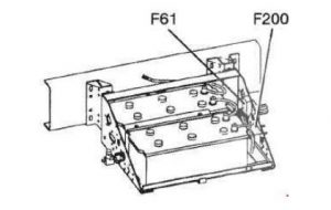
F61 50 Windscreen defrosting
F200 200 Power supply (before master switch)

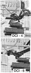
Preheating relay (R93)

Renault Midlum - fuse box diagram - preheating relay (R93)
Renault Midlum – fuse box diagram – preheating relay (R93)

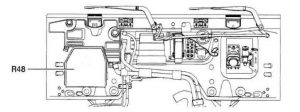
Windscreen defrosting relay (time-delayed) (R48)

Renault Midlum - fuse box diagram - windscreen defrosting relay time delayed (R48)
Renault Midlum – fuse box diagram – windscreen defrosting relay time delayed (R48)

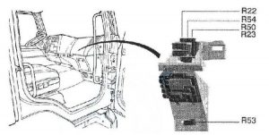
Relay

Renault Midlum - fuse box diagram - relay
Renault Midlum – fuse box diagram – relay
Number Relay
R22 Neutral relay
R23 Revolving beacon(s) relay
R50 Available power supplies relay (bodybuilder equipment)
R53 Headlamp washer time-delay relay
R54 Reversing lights relay


Number Relay
R34 Zero speed relay
“ALLISON” gearbox zero speed relay
R70 Exhaust brake cut-off relay

WARNING: Terminal and harness assignments for individual connectors will vary depending on vehicle equipment level, model, and market.
Renault Master (1997 – 2003) – fuse box diagram

Renault Master (1997 – 2003) – fuse box diagram

Year of production: 1997, 1998, 1999, 2000, 2001, 2002, 2003

Passenger compartment fuse box

Renault Master - fuse box diagram - passenger compartment
Renault Master – fuse box diagram – passenger compartment
Fuse Ampere riting [A] Description
F1 5 Injection computer + after ignition feed – starter relay – gearbox computer – after ignition relay 1 – diagnostic socket
F2 10  UCH supply – first row cigarette lighter -door locking – heated rear screen – idle speed regulator – rear fog light relay – gear selector light – air conditioning control panel – cruise control – cruise control stop switch – variable damping – headlight adjustment – heated windscreen deicing – parking proximity sensor computer -cruise control – gearbox load control – controlled suspension computer
F3 30 Washer/wiper combination switch – UCH
F4 15 Instrument panel – pretensioner and airbag computer – Tachograph
F5 15 Brake switch – alternator – reversing light switch – reversing light relay
F6 15 Washer/wiper combination switch – windscreen wiper motor
F7 5 ABS – vehicle speed sensor
F8 15 Air conditioning control relay – diesel heater relay – engine fuse board (position B track 4, for additional adaptations on reversal bornier (16-seater bus))
F9 10 Radio – multifunction display – car phone communication interface – central communication unit
F10 30 Air conditioning control panel
F11 10 Cigarette lighter
F12 15 Accessories socket
F13 5 Injection computer – reversal bornier for additional adaptations (16-seater bus)
F14 5 Left-hand side light – left-hand rear light – multifunction display – central communication unit
F15 5 Right-hand side light – right-hand rear light – right-hand number plate light – caravan connection – Tachograph – instrument panel
F16 10 Left-hand dipped beam headlight – headlight adjustment control – instrument panel
F17 10 Right-hand dipped beam headlight
F18 10 Left-hand main beam headlight – instrument panel
F19 10 Right-hand main beam headlight
F20 10 Rear fog light relay – caravan connection
F21 15 Horn
F22 5 Heated door mirrors
F23 20 Heated right-hand rear quarter panel
F24 20 Heated left-hand rear quarter panel
F25 10 16-seater bus: Front door electric locking
F26 15 16-seater bus: Rear right-hand door electric locking
F27 5 except 16-seater bus: Controlled suspension computer
F28 15 Tachograph – instrument panel – alarm siren – diagnostic socket – alarm sensor UCH
F29 10 Radio – multifunction display – car phone communication interface – central communication unit
F30
F31 5 Impact sensor – UCH
F32 15 Heated front seats – electric door mirror control
F33 20 Driver’s control for front passenger electric window – passenger electric window control
F34 20 Electric window timer
F35 20 Diesel heater relay
F36 15 except 16-seater bus: Hazard warning lights
16-seater bus: Hazard warning lights – Tachograph – instrument panel – alarm siren – diagnostic socket – alarm sensor
F37 30 Door control
F38 30 16-seater bus: Consumer cut-out (fuse F36 supply)
F39 30 Consumer cut-out (supply to fuses F27, F28, F29 and F31)

Passenger Compartment Fuse Modules (except 16-seater bus)

These modules are mounted on the passenger compartment relay board, on the left-hand dashboard fascia.

Renault Master - fuse box diagram - passenger compartment (except 16-seater bus)
Renault Master – fuse box diagram – passenger compartment (except 16-seater bus)
Number Ampere rating [A] Description
F1 25 9-seater bus: + Battery feed before battery cut-off heating output
F2 9-seater bus: Not in use
F3 25 9-seater bus: Condenser relay
F4 5 9-seater bus: + Battery feed before battery cut-off heating control
Relay
A + After ignition 1
B
C Passenger compartment fan assembly speed 4
D Independent heating cut-off
E Heated rear screen and door mirrors
R1 9-seater bus: Air conditioning + after ignition feed
R2 9-seater bus: Condenser
720 Air conditioning cut-off
731 Heated windscreen


Passenger Compartment Fuse Modules (16-seater bus)

These modules are mounted on the passenger compartment relay board, on the left-hand dashboard fascia.

Renault Master - fuse box diagram - passenger compartment (16-seater bus)
Renault Master – fuse box diagram – passenger compartment (16-seater bus)
Fuse Ampere riting [A] Description
Module 1 (M1)
F1 15 Condenser relay
F2 25 + After ignition relay 2
F3 30 Electric door power after battery cut-off
F4
Module 2 (M2)
F1 15 Battery cut-off relay
F2 5 + Battery feed before battery cut-off heating control
F3 25 + Battery feed before battery cut-off heating output
F4 15 Operating light and footwell signal + battery feed after battery cut-off
Module 3 (M3)
F1 10 + After ignition relay 2 supply (299-752) – electric doors – passenger lighting – central door locking
F2 5 Emergency stop – switch open
F3 5 Rear door locks + after ignition
F4
Relay
720 Air conditioning cut-off
Top row
A + After ignition 1
B Fog lights
C Passenger compartment fan assembly speed 4
D Independent heating cut-off
E Heated rear screen and door mirrors
Bottom row
A Battery cut-out
B Battery cut-out locking
C + After ignition 2
D Evaporator
E Condenser

WARNING: Terminal and harness assignments for individual connectors will vary depending on vehicle equipment level, model, and market.
Renault Modus (2004 – 2007) – fuse box diagram

Renault Modus (2004 – 2007) – fuse box diagram

Year of production: 2004, 2005, 2006, 2007

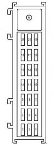
Passenger compartment fuse box

Renault Modus - fuse box diagram - passenger compartment
Renault Modus – fuse box diagram – passenger compartment
Renault Modus - fuse box diagram - passenger compartment
Renault Modus – fuse box diagram – passenger compartment
Fuse Ampere riting [A] Description
F1 30 UCH
F2 15 Instrument panel – air conditioning control unit – fuse and relay box
F3
F4 15 Main electromagnetic horn – diagnostic socket – driving school control monitor
F5 7,5 UCH
F6 25 Driver’s electric window motor – child safety lock control
F7 25 Driver’s dual front electric window control
F8 10 ABS computer – electronic stability program – cluster sensor
F9 10 First row cigarette lighter
F10 20 Passenger compartment fan assembly 1
F11 20 Passenger compartment fan assembly 1
F12 15 Air conditioning control unit – climate control control panel – radio – steering wheel controls – radio telephone central unit – front and rear bi-directional washer pump – power supply fuse board – passenger compartment fuse and relay box 2 – driver’s heated seat – passenger heated seat – self-supplied alarm siren
F13 10 Passenger compartment fuse and relay box 2 – brake switch
F14
F15 20 Rear screen wiper motor
F16 7,5 Driver’s electric door mirror – passenger electric door mirror
F17 30 UCH
F18 15 UCH – engine immobiliser
F19 5 Rain and light sensor – passenger compartment fan sensor
F20 10 Consumer cut-out – instrument panel – radio – radio telephone central unit – electric door mirror switch – self-supplied alarm siren – pressure monitoring system central unit pneumatic
DIODE
F21 Child safety lock control
RELAY
A 50 + Accessories feed

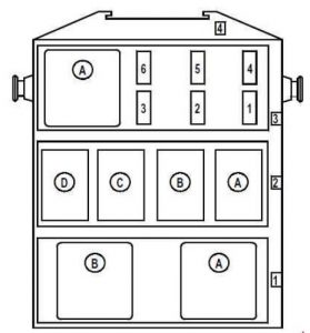
Passenger compartment relay and fuse box 2

This unit is secured to the instrument panel cross member, underneath the passenger airbag.

Renault Modus - fuse box diagram - passenger compartment relay and fuse box
Renault Modus – fuse box diagram – passenger compartment relay and fuse box
Number Ampere rating [A] Circuit
Fuse and relay board (row 3)
F1 20 Driver’s and passenger door deadlocking relay feed (relay A on plate 1531, row 2) on right-hand drive version
F2 20 Driver’s heated seat – passenger heated seat
F3 15 Sunroof central unit
F4 25 Driver’s dual rear electric window control supply relay (relay A on plate 1531 row 1)
F5
F6
Relay
A
Relay board (row 2)
A 20 Driver’s and passenger door central locking (on right-hand drive version)
B 20 Brake lights
C
D
Relay plate (row 1)
A 50 Driver’s dual rear electric window control
B 50 Driver’s left and right-hand rear electric window control


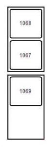
Relay board

This unit is located under the dashboard on the left-hand side of the passenger compartment fan assembly.

Renault Modus - fuse box diagram - relay board
Renault Modus – fuse box diagram – relay board
Fuse Ampere riting [A] Description
1067 35 Auxiliary heater 1
1068 50 Instrument panel – air conditioning control unit – fuse and relay box
1069 50 Auxiliary heater 3 (1500 Watt version)

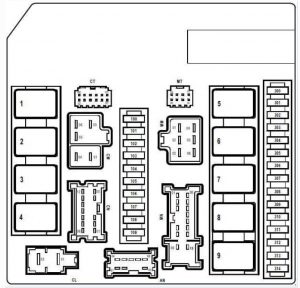
Engine compartment fuse box

This unit is located in the engine compartment, behind the left-hand headlight.

Renault Modus - fuse box diagram - engine compartment
Renault Modus – fuse box diagram – engine compartment
Fuse Ampere riting [A] Description
100 25 ABS computer or Electronic Stability Program
101
102 10 Right-hand main beam headlights
103 10 Left-hand main beam headlights
104 10 Right-hand side light – rear right-hand light – right-hand heated seat control – electronic stability programme on/off button – rear right-hand electric window control – climate control control panel -air conditioning control unit – central door locking switch – CD changer – speed limiter on/off control – on right-hand drive version: – driver’s dual rear electric window control – child safety lock control – driver’s dual front electric window control – electric door mirror control – passenger electric window control
105 10 Left-hand side light – rear left-hand light – left-hand heated seat control – right-hand license plate light – left-hand license plate light – first row cigarette lighter – headlight height adjustment control – rear left-hand electric window control – radio – gear lever display – poor traction control – on left-hand drive version: – driver’s dual rear electric window control – child safety lock control – driver’s dual front electric window control – electric door mirror control – passenger electric window control
106 15 Shift pattern control – UPC – auxiliary heater relay – power assisted steering / gear lever display diagnostic socket – hands-free kit – radio telephone central unit – driving school monitor control – central unit Tyre pressure monitor / central unit discharge bulbs
107 20 Windscreen wiper motor
108 15 Right-hand headlight / right-hand headlight adjustment motor
109 15 Left-hand headlight / left-hand headlight adjustment motor
300 10 Air conditioning compressor clutch
301
302 25 Starter motor solenoid
303 20 + Protected automatic clutch computer battery feed
304
305 15 Heated rear screen
306 15 Headlight washer supply relay (relay A and B on board 777)
307 5 + Automatic gearbox computer after ignition feed
308
309 10 Reversing lights
310 20 Ignition coils feed
311 20 + Protected injection computer battery feed
312 10 + Airbag and pretensioner after ignition feed
313 10 + Injection computer after ignition feed
314 20 Front left and right-hand fog lights
Relay
1 Heated rear screen
2 Injection locking
3 Dipped beam headlights
4 Front headlights
5 Starter
6
7 Engine cooling fan high-speed
8 Engine cooling fan low-speed
9 + After ignition feed

Protected positive battery unit

This unit is located on the positive battery terminal.

Renault Modus - fuse box diagram - protective positive battery unit
Renault Modus – fuse box diagram – protective positive battery unit
Number Ampere riting [A] Description
Main fuse (mark 1)
350 Fuse inputs F2 to F8 feed on power supply fuse board – starter – alternator – supply to fuses marked 2 and 3 on protected battery unit
Fuse marked 2 (BLUE connector)
A 70 Fuse inputs F17 and F18 feed passenger compartment fuse and relay unit – UPC
B 60 Electric power assisted steering system
Fuse marked 3 (GREEN connector)
A 70 Fuse inputs F1, F3, F5 feed and accessories relays on passenger compartment fuse and relay unit
B 60 UPC

Power feed fuse board

This unit is located on the front side of the battery tray. Allocation of fuses and relays (according to equipment level).

Renault Modus - fuse box diagram - power feed fuse board
Renault Modus – fuse box diagram – power feed fuse board
Number Ampere riting [A] Description
F1 30 Injection central unit supply relay on K9K or 764 engine (R5 relay on optional relay unit)
F2 30 Sequential gearbox electric pump unit relay on D4F engine with sequential gearbox
Preheating unite on K9K engines
F3 30 Air conditioning and cooling fan assembly on K9K and D4F engines with sequential gearbox
F4 30 Air conditioning and cooling fan assembly on K4M / K4J / D4F engines with manual gearbox
Sequential gearbox electric pump unit relay on K9K engines with sequential gearbox
F5 50 F12 fuse input feed – fuses F1, F2, F3, F4 input feeds on passenger compartment fuse and relay box 2
F6 80 Passenger compartment auxiliary heater
F7 60 Passenger compartment auxiliary heater
F8 50 ABS computer
F9
F10
F11
F12 10 Left-hand headlights supply relay >on discharge bulb version
Relay
A 20 Headlight washer pump
B 20 Headlight washer pump relay
C 20 Left-hand headlights on discharge bulb version


Optional relay board

This unit is secured to the front of the battery tray, on the engine side.

Renault Modus - fuse box diagram - optional relay board
Renault Modus – fuse box diagram – optional relay board
Number Ampere riting [A] Description
R1
R2
R3
R4 50 Sequential gearbox electric pump unit
R5 50 Injection central unit on K9K 764 engine

WARNING: Terminal and harness assignments for individual connectors will vary depending on vehicle equipment level, model, and market.

Renault 25 (1983 – 1992) – fuse box diagram

Renault 25 (1983 – 1992) – fuse box diagram

Year of production: 1983, 1984, 1985, 1986, 1987, 1988, 1989, 1990, 1991, 1992

Fuse box

Renault 25 - fuse box diagram
Renault 25 – fuse box diagram
Fuse Ampere riting [A] Circuit
BLACK
1 20 1983-1986: Rear window de-icer
30 since 1987: Rear window de-icer with time delay
2 10 1983-1987: Fixed wiper park position
15 since 1988: Fixed wiper park position, diagnostic socket
3 15 1983-1984: Cigar lighter, roof light, plip
5 since 1985: Roof light, plip
4 25 Central locking, +before ignition seat memory
5 30 +Before ignition caravan feed, seat/neon (limousine)
6 15 since 1986: +Before ignition, rear window fixed wiper park position
PINK
1 2 3 speed automatic transmission
5 4 speed automatic transmission
2 5 1983-1984: +After ignition, heating/air conditioning control
10 since 1985: +After ignition, heating/air conditioning control
3 25 since 1989: +After ignition, cigar lighter, reversing light, automatic transmission selector, cruise control, adjusting sea
4 15 since 1989: Front fog light
5 30 1983-1988: Left-hand seat
20 since 1989: Cooling fan
6 30 1983-1988: Right-hand seat
since 1989: Right-hand and left-hand seats
BROWN
1 25 Heating, air conditioning
2 10 Radio, alarm
3 7,5 Rear fog light
4 10 Direction indicator (central flasher unit)
5 5 Left-hand side light, bulb monitor, lighting switches
6 5 Right hand side light, bulb monitor, lighting rheostat, lighting switches
GRAY
1 10 1983-1984: Windscreen wiper
15 since 1985: Windscreen wiper
2 5 1983-1984: Reversing light
15 1985-1988: Reversing light, cigar lighter
7,5 since 1989: Reversing light
3 3 Instrument panel, automatic transmission selector lighting, voice synthesizer
4 10 Stop lights, cruise control (1989), “lights on” warning buzzer
5 30 Left-hand window, electrically operated rear-view mirrors
6 30 Right hand window, sun roof

Relay Box

Renault 25 - fuse box diagram - relay box
Renault 25 – fuse box diagram – relay box
Number Circuit
1 B298: Rpm relay
B295: Coolant level sensor unit
1988-1991: Cruise control relay
2 Wiper timer relay
3 Interior lights timer relay
4 Door locking timer relay
5 “Lights on” reminder buzzer
6 Flasher unit
Circuit cut-out relay
7 Headlamp relay
Arabia: Excess speed relay
V6 since 1991: Low fuel level relay
8 Air conditioning relay
Shunt
9 Lighting rheostat relay
10 Rear screen de-icer relay
Rear screen de-icer timer unit
11 Starter relay (automatic transmission), Shunt (manual transmission)
12 Junction with wiring harness, driver’s door
13 Junction with wiring harness, driver’s door
14 General power supply
15 Flasher unit


WARNING: Terminal and harness assignments for individual connectors will vary depending on vehicle equipment level, model, and market.

Toyota Hilux (2015 – 2018) – fuse box diagram

Toyota Hilux (2015 – 2018) – fuse box diagram

Year of production: 2015, 2016, 2017, 2018

Passenger Compartment Fuse Box

Toyota Hilux - fuse box diagram - passenger compartment
Toyota Hilux – fuse box diagram – passenger compartment
Fuse Ampere Circuit
1 DOOR NO.2 25 Power Window
2 DOOR R/L 25 Power Window
3 DOOR R/R 25 Power Window
4 DOOR NO.1 30 Power Window
5 ETCS 10 1GR-FE, 1KD-FTV, 2KD-FTV, 1TR-FE, 2TR-FE, 5L-E: Multiport Fuel Injection System/Sequential Multiport Fuel Injection System
EFI-MAIN NO.1 25 1GD-FTV, 2GD-FTV: ABS, Air Conditioner, Downhill Assist Control, Multiport Fuel Injection System/Sequential Multiport Fuel Injection System, Hill-Start Assist Control, TRC, VSC
6 EFI-MAIN NO.1 25 1GR-FE, 1KD-FTV, 2KD-FTV, 1TR-FE, 2TR-FE, 5L-E: ABS, Air Conditioner, Downhill Assist Control, Multiport Fuel Injection System/Sequential Multiport Fuel Injection System, Hill-Start Assist Control, TRC, VSC
EFI-MAIN NO.2 25 1GD-FTV, 2GD-FTV: Multiport Fuel Injection System/Sequential Multiport Fuel Injection System
7 TURN&HAZ 10 Turn Signal and Hazard Warning Light, Combination Meter, Door Lock Control, Entry & Start System, Immobiliser System, Starting, Steering Lock, Theft Deterrent, Wireless Door Lock Control
8 AM2 NO.2 30 Multiport Fuel Injection System/Sequential Multiport Fuel Injection System, Entry & Start System, Immobiliser System, Starting, Steering Lock, Wireless Door Lock Control
9 HTR 40 Air Conditioner, Charging
10 AM1 40 Entry & Start System, Immobiliser System, Starting, Steering Lock, Wireless Door Lock Control
11 TAIL 10 1GR-FE, 1KD-FTV, 2KD-FTV, 1TR-FE, 2TR-FE, 5L-E: Taillight, Illumination, Automatic Light Control, Charging, Entry & Start System, Front Fog Light, Immobiliser System, Key Reminder, Light Reminder, Rear Fog Light, Starting, Steering Lock, Wireless Door Lock Control
ECU-ALT NO.2 10 1GD-FTV, 2GD-FTV: Door Lock Control, Power Window, Theft Deterrent
12 FOG FR/DRL 10 Front Fog Light, Headlight, Illumination, Taillight
13 ECU-ALT NO.2 10 1GR-FE, 1KD-FTV, 2KD-FTV, 1TR-FE, 2TR-FE, 5L-E: Door Lock Control, Power Window, Theft Deterrent
TAIL 10 1GD-FTV, 2GD-FTV: Taillight, Illumination, Automatic Light Control, Charging, Entry & Start System, Front Fog Light, Immobiliser System, Key Reminder, Light Reminder, Rear Fog Light, Starting, Steering Lock, Wireless Door Lock Control
14 OBD 10 On-Board Diagnosis System
15 EFI NO.1 10 ABS, Air Conditioner, Downhill Assist Control, Multiport Fuel Injection System/Sequential Multiport Fuel Injection System, Hill-Start Assist Control, Stop & Start System, TRC, VSC
16 IG2 NO.1 5 Multiport Fuel Injection System/Sequential Multiport Fuel Injection System
17 METER 5 Combination Meter, 4WD, ABS, Air Conditioner (Automatic), Audio System, Charging, Door Lock Control, Downhill Assist Control, Multiport Fuel Injection System/Sequential Multiport Fuel Injection System, Entry & Start System, Headlight, Headlight Beam Level Control (Automatic), Headlight Cleaner, Hill-Start Assist Control, Illumination, Immobiliser System, Interior Light, Key Reminder, Lane Departure Alert, Light Reminder, Navigation System, Pre-Collision System, Rear View Monitor System, Seat Belt Warning, SRS, Starting, Steering Lock, Stop & Start System, Taillight, Telematics System, Theft Deterrent, Tire Pressure Warning System, TRC, Turn Signal and Hazard Warning Light, VSC, Wireless Door Lock Control
18 A/BAG 5 SRS Airbag System
19 IG2 NO.3 5 Charging, Multiport Fuel Injection System/Sequential Multiport Fuel Injection System, Immobiliser System, Multiplex Communication System, Telematics System
20 SFT LOCK-ACC 10 Shift Lock
21 P/OUTLET NO.1 15 Power Outlet
22 IG2 NO.2 5 Entry & Start System, Immobiliser System, Starting, Steering Lock, Wireless Door Lock Control
23 WIPER 25 Front Wiper and Washer
24 IG1 NO.1 10 Audio System, Back-Up Light, Charging, Combination Meter, Multiport Fuel Injection System/Sequential Multiport Fuel Injection System, Lane Departure Alert, Navigation System, Rear View Monitor System
25
26 IG1 NO.3 10 ABS, Downhill Assist Control, Hill-Start Assist Control, Stop & Start System, TRC, VSC
27 IG1 NO.4 10 Air Conditioner, Audio System, Automatic Light Control, Charging, Combination Meter, Door Lock Control, Multiport Fuel Injection System/Sequential Multiport Fuel Injection System, Entry & Start System, Front Fog Light, Headlight, Headlight Beam Level Control (Automatic), Headlight Cleaner, Illumination, Immobiliser System, Interior Light, Mirror Heater, Multiplex Communication System, Navigation System, Power Outlet, Power Window, Rear Fog Light, Rear View Monitor System, Rear Window Defogger, Seat Belt Warning, SRS, Starting, Steering Lock, Stop & Start System, Taillight, Theft Deterrent, Tire Pressure Warning System, Wireless Door Lock Control
28 WASHER 15 Front Wiper and Washer
29 IG1 NO.2 10 Charging, Shift Lock

Passenger Compartment Relay Box No.1

Toyota Hilux - fuse box diagram - passenger compartment (box 1)
Toyota Hilux – fuse box diagram – passenger compartment (box 1)
Fuse Ampere Circuit
1 DCU NO.1 25 Urea Pump Control ECU
2 DCU NO.2 20 Urea Pump Control ECU
3 NOX PM 20 Nitrogen Oxides Sensor
4 DCU-B 7,5 Urea Pump Control ECU
5 DEF-S 10 Mirror Heater, Multiport Fuel Injection System/Sequential Multiport Fuel Injection System
6 FOG RR 10 Rear Fog Light
7 DEICER 15 Windshield Wiper De-icer
8 DEF 25 Rear Window Defogger, Mirror Heater, Multiport Fuel Injection System/Sequential Multiport Fuel Injection System

Relay

Relay Description
R1 Urea Pump (DCU-MAIN)
R2 Nitrogen Oxides Sensor (NOX PM)
R3 Windshield Wiper De-icer (DEICER)
R4 Rear fog light (FOG RR)
R5
R6 Inverter (INV)
R7 Rear Window Defogger, Mirror Heater (DEF)

Passenger Compartment Relay Box No.2

Toyota Hilux - fuse box diagram - passenger compartment (box 2)
Toyota Hilux – fuse box diagram – passenger compartment (box 2)
Fuse Ampere Circuit
1 ACC 5 4WD, ABS, Air Conditioner, Audio System, Charging, Clock, Combination Meter, Door Lock Control, Downhill Assist Control, Multiport Fuel Injection System/Sequential Multiport Fuel Injection System, Entry & Start System, Headlight, Headlight Beam Level Control (Automatic), Headlight Cleaner, Hill-Start Assist Control, Illumination, Immobiliser System, Interior Light, Key Reminder, Lane Departure Alert, Light Reminder, Multiplex Communication System, Navigation System, Pre-Collision System, Rear View Monitor System, Remote Control Mirror, Seat Belt Warning, SRS, Starting, Steering Lock, Stop & Start System, Taillight, Telematics System, Theft Deterrent, Tire Pressure Warning System, TRC, Turn Signal and Hazard Warning Light, VSC, Wireless Door Lock Control
2 A/C 10 Air Conditioner (Manual)
3 ECU-IG2/
C/OPN NO.2
10 Multiport Fuel Injection System/Sequential Multiport Fuel Injection System
4 STA/WIPER-S 7,5 Starting, Multiport Fuel Injection System/Sequential Multiport Fuel Injection System
5
6 4WD-IG 20 4WD
7 S/HTR 15 Before Aug. 2017: Seat Heater
S/HTR/S/VENT 15 From Aug. 2017: Seat Heater
8 IG1 NO.5 10 Air Conditioner, Lane Departure Alert, Pre-Collision System

Relay

Relay Description
R1 Heater (HTR)
R2 Ignition (IG1 NO.2)
R3 Ignition (IG2)
R4 LHD: Heated Steering Wheel (STRG HTR)
R5 Air Conditioner (A/C COMP)

Passenger Compartment Relay Box No.3

Toyota Hilux - fuse box diagram - passenger compartment (box 3)
Toyota Hilux – fuse box diagram – passenger compartment (box 3)

Relay

Relay Description
R1 PTC Heater (PTC HTR NO.1)
R2 PTC Heater (PTC HTR NO.3)
R3 PTC Heater (PTC HTR NO.2)
R4 Viscous Heater (VISCOUS)
R5
R6 Door Lock (D/L NO.1)
R7 Door Lock (D/L NO.2)
R8 RHD: Door Lock (D/L NO.2)
R9 RHD: –

Passenger Compartment Relay Box No.4

Toyota Hilux - fuse box diagram - passenger compartment (box 4)
Toyota Hilux – fuse box diagram – passenger compartment (box 4)

Relay

Relay Description
R1 Daytime Running Light (DRL)
R2 Theft Deterrent (S-HORN)
R3 Front Fog Lights (FOG FR)
R4 Taillight (TAIL)
R5 Interior Lights (DOME CUT)
R6 Ignition (IG1 NO.1

Engine Compartment Fuse Box

Toyota Hilux - fuse box diagram - engine compartment
Toyota Hilux – fuse box diagram – engine compartment
Fuse Ampere Circuit
1
2
3
4 INV 20 Power Outlet (Voltage Inverter)
5 ECU-ALT NO.1 10 Double Locking
6
7 STOP 10 From Aug. 2017: Stop Light, ABS, TRC, VSC, Multiport Fuel Injection System/Sequential Multiport Fuel Injection System, Charging, Downhill Assist Control, Entry & Start System, Hill-Start Assist Control, Immobiliser System, Shift Lock, Starting, Steering Lock, Wireless Door Lock Control
8 STOP 10 Before Aug. 2017: Stop Light, ABS, TRC, VSC, Multiport Fuel Injection System/Sequential Multiport Fuel Injection System, Charging, Downhill Assist Control, Entry & Start System, Hill-Start Assist Control, Immobiliser System, Shift Lock, Starting, Steering Lock, Wireless Door Lock Control
STRG HTR 10 From Aug. 2017: Heated Steering Wheel
9 4WD-ALT 10 4WD
10 ECU-B NO.1 10 4WD, Multiport Fuel Injection System/Sequential Multiport Fuel Injection System, ABS, Air Conditioner (Automatic), Audio System, Charging, Clock, Combination Meter, Door Lock Control, Double Locking, Downhill Assist Control, Entry & Start System, Headlight, Headlight Beam Level Control (Automatic), Headlight Cleaner, Hill-Start Assist Control, Illumination, Immobiliser System, Interior Light, Key Reminder, Lane Departure Alert, Light Reminder, Navigation System, Pre-Collision System, Rear View Monitor System, Seat Belt Warning, SRS, Starting, Steering Lock, Stop & Start System, Taillight, Telematics System, Theft Deterrent, Tire Pressure Warning System, TRC, Turn Signal and Hazard Warning Light, VSC, Wireless Door Lock Control
11 RADIO 10 Audio System, Navigation System, Rear View Monitor System
12 DOME 10 Immobiliser System, Entry & Start System, Interior Light, Starting, Steering Lock, Theft Deterrent, Wireless Door Lock Control
13 H-LP RH-LO 10 Right-Hand Headlight (Low Beam)
14 H-LP LH-LO 10 Left-Hand Headlight (Low Beam), Headlight Beam Level Control, Headlight Cleaner
15 H-LP RH-HI 10 Right-Hand Headlight (High Beam)
16 H-LP LH-HI 10 Left-Hand Headlight (High Beam)
17 S-HORN 7,5 Theft Deterrent
18 MAYDAY 7,5 Telematics System
19 HORN 10 Horn, Entry & Start System, Immobiliser System, Starting, Steering Lock, Theft Deterrent, Wireless Door Lock Control
20 EFI-B 7,5 Multiport Fuel Injection System/Sequential Multiport Fuel Injection System
21 ALT-S/ICS 7,5 Charging
22 SMART 7,5 Entry & Start System, Immobiliser System, Starting, Steering Lock, Wireless Door Lock Control
23 ECU-B NO.3 10 Air Conditioner (Automatic), Multiport Fuel Injection System/Sequential Multiport Fuel Injection System, Entry & Start System, Immobiliser System, Mirror Heater, Multiplex Communication System, Starting, Steering Lock, Theft Deterrent, Wireless Door Lock Control
24 A/F HTR 20 1GR-FE, 1TR-FE, 2TR-FE: Air Fuel Ratio Sensor
EDU 25 1GD-FTV, 2GD-FTV, 1KD-FTV, 2KD-FTV, 5L-E: Multiport Fuel Injection System/Sequential Multiport Fuel Injection System
25 STRG LOCK/
AM2 NO.1
10 Multiport Fuel Injection System/Sequential Multiport Fuel Injection System, Entry & Start System, Immobiliser System, Starting, Steering Lock, Wireless Door Lock Control
26 INJ 15 1GR-FE, 1TR-FE, 2TR-FE: Combination Meter, Multiport Fuel Injection System/Sequential Multiport Fuel Injection System, Ignition
ST NO.2 30 2GD-FTV with Stop & Start System: Entry & Start System, Immobiliser System, Starting, Steering Lock, Wireless Door Lock Control
27 ECU-B NO.2 10 Entry & Start System, Immobiliser System, Starting, Steering Lock, Wireless Door Lock Control
28 ECU-B NO.4 25 Automatic Light Control, Door Lock Control, Entry & Start System, Front Fog Light, Headlight, Illumination, Immobiliser System, Interior Light, Power Window, Rear Fog Light, Starting, Steering Lock, Taillight, Theft Deterrent, Wireless Door Lock Control
29
30 D/C CUT 30 “ECU-B NO.1”, “RADIO”, “DOME” Fuses
31 ODS 7,5 Occupant Detection ECU
32 P/SEAT 30 Before Aug. 2017: Power Seat
P/SEAT(D) 30 From Aug. 2017: Power Seat
33 PTC HTR NO.2 30 PTC Heater
34
35 ABS NO.1 50 ABS, TRC, VSC, Downhill Assist Control, Hill-Start Assist Control
36 ABS NO.2 30 ABS, TRC, VSC, Downhill Assist Control, Hill-Start Assist Control
37 R/B I/P-ALT 30 “IG1 NO.2” Relay: “4WD-IG”, “S/HTR”, “S/HTR/S/VENT”, “IG1 NO.5” Fuses
38
39
40 PTC HTR NO.1 50 PTC Heater
41 GLOW 80 Glow System
42 J/B-B 60 “EFI-MAIN NO.1” Relay, “EFI-MAIN NO.2” Relay, “EFI-MAIN NO.1”, “EFI-MAIN NO.2”, “TURN&HAZ”, “ETCS”, “EFI NO.1”, “AM2 NO.2” Fuses
43 H-LP CLN 30 Headlight Cleaner
44 CDS FAN/
PTC HTR NO.3
30 Air Conditioner, PTC Heater, Electric Cooling Fan
45 R/B FLOOR-ALT 50 “DEF” Relay, “DEF”, “FOG RR”, “DEICER”, “DEF-S” Fuses
46 ALT 140 “P/W” Relay, “ACC” Relay, “R/B FLOOR-ALT”, “R/B I/P-ALT”, “4WD-ALT”, “INV”, “ABS NO.1”, “ABS NO.2”, “STOP”, “P/SEAT”, “P/SEAT (D)”, “H-LP CLN”, “STRG HTR”, “ECU-ALT NO.1”, “PTC HTR NO.1”, “PTC HTR NO.2”, “CDS FAN/PTC HTR NO.3”, “HTR”, “DOOR R/L”, “DOOR NO.1”, “DOOR R/R”, “DOOR NO.2”, “FOG FR/DRL”, “TAIL”, “OBD”, “ECU-ALT NO.2”, “AM1”, “P/OUTLET NO.1”, “SFT LOCK-ACC” Fuses
47 BBC NO.3 40 Stop & Start System
48
49 BBC NO.1 40 Stop & Start System
50 ST NO.1 30 1GR-FE, 1TR-FE, 2TR-FE: Entry & Start System, Immobiliser System, Starting, Steering Lock, Wireless Door Lock Control
50 1GD-FTV, 2GD-FTV, 1KD-FTV, 2KD-FTV, 5L-E: Entry & Start System, Immobiliser System, Starting, Steering Lock, Wireless Door Lock Control
51
52
53 AIR PMP 50 Air Pump
DCU-MAIN 50 “DCU-MAIN” Relay, “DCU NO.1”, “DCU NO.2”, “DCU-B”, “NOX PM” Fuses
54 H-LP MAIN 40 “H-LP” Relay, “DIMMER” Relay, “H-LP LH-LO”, “H-LP RH-LO”, “H-LP LH-HI”, “H-LP RH-HI” Fuses

Relay

Relay Description
R1 Dimmer
R2 Headlight (H-LP)
R3 1GD-FTV, 2GD-FTV, 1KD-FTV, 2KD-FTV, 5L-E: Starter (ST NO.1)
R4 1GR-FE, 1TR-FE, 2TR-FE: Starter (ST NO.1)
2GD-FTV with Stop & Start System: Starter (ST NO.2)
R5 Stop Lights / Electric cooling fan (STOP/CDS FAN)
R6 1GR-FE, 1TR-FE, 2TR-FE: Fuel Injector (INJ)
1GD-FTV, 2GD-FTV, 1KD-FTV, 2KD-FTV, 5L-E: Injector Driver (EDU)
R7 Horn
R8 1GD-FTV, 2GD-FTV, 1KD-FTV, 2KD-FTV, 5L-E:  Glow System (GLOW)
1GR-FE, 1TR-FE, 2TR-FE: Fuel Pump / Air Pump (FUEL PMP/AIR PMP HTR)
R9 1GR-FE, 1TR-FE, 2TR-FE: Air Fuel Ratio Sensor (A/F HTR)


WARNING: Terminal and harness assignments for individual connectors will vary depending on vehicle equipment level, model, and market.
Audi A4 Cabriolet (2009) – fuse box diagram

Audi A4 Cabriolet (2009) – fuse box diagram

Year of production: 209

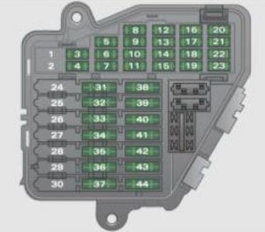
Instrument panel (driver’s side)

Audi A4 Cabriolet - fuse box diagram - instrument panel
Audi A4 Cabriolet – fuse box diagram – instrument panel
Number Electric equipment Ampere rattings [A]
1 Air conditioner 10
2 Footwell illumination 5
3 Heated washer jets 5
4 Radiator fan 5
5 Telephone, oil level sensor, multifunction switch, rear heated Seat, shift gate 10
6 Air conditioner (air quality sensor), air pressure sensor 5
7 Electronic Stabilization Program (ESP), brake light switch, clutch pedal switch, steering angle sensor 10
8 Telephone 5
9 Brake booster (vacuum pump) 15
10 Automatic headlight beam adjustment, automatic headlight range control, right 5
11 Airbag control unit, front passenger seat recognition USA (bladder mat) 10
12 Diagnosis socket 10
13 Steering column module 10
14 Brake lights 10
15 Instrument cluster, Navigation system 10
16 Garage door opener 5
17 Level, tire pressure control, park assist, light/rain sensor 10
18 Automatic headlight range control, left 5
19 Fog lights 15
20
21
22 Doors 15
23
24 Central convenience electrical system 20
25 Heater blower 30
26 Rear window defogger 30
27 Socket for trailer towing (controller) 30
28 Fuel pump 20
29
30 Power top control unit 30
31 Automatic transmission, mirror dimming, diagnosis socket 15
32 Towing assembly 15
33 Cigarette lighter 20
34 Electrical socket 20
35 Luggage compartment socket 20
36 Windshield wiper system 30
37 Pump for windshield and headlight washer * system 30
38 Central elect ric, anti -theft alarm system, rear lid/ trunk release 15
39 Radio 20
40 Horn 25
41 Auxiliary heat ing 30
42 Electronic Stab ilization Program (ESP) 25
43 Engine timing 15
44 Seat heating 35


WARNING: Terminal and harness assignments for individual connectors will vary depending on vehicle equipment level, model, and market.
Audi A4 Avant (2008) – fuse box diagram

Audi A4 Avant (2008) – fuse box diagram

Year of production: 2010

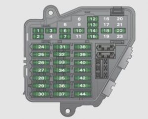
Instrument panel (driver’s side)

Audi A4 Avanti - fuse box diagram - instrument panel
Audi A4 Avanti – fuse box diagram – instrument panel
Number Electric equipment Ampere rattings [A]
1 Air conditioner 10
2 Footwell illumination 5
3 Heated washer jets 5
4 Radiator fan 5
5 Telephone, oil level sensor, multifunction switch, rear heated Seat, shift gate 10
6 Air conditioner (air quality sensor), air pressure sensor 5
7 Electronic Stabilization Program (ESP), brake light switch, clutch pedal switch, steering angle sensor 10
8 Telephone 5
9 Brake booster (vacuum pump) 15
10 Automatic headlight beam adjustment, automatic headlight range control, right 5
11 Airbag 5
12 Diagnosis socket 10
13 Steering column module 10
14 Brake lights 10
15 Instrument cluster, Navigation system 10
16 Garage door opener 5
17 Level, tire pressure control, park assist, light/rain sensor 10
18 Automatic headlight range control, left 5
19 Fog lights, rear fog light 15
20
21
22 Front doors 15
23 Rear doors 15
24 Central convenience electrical system 20
25 Heater blower 30
26 Rear window defogger 30
27 Socket for trailer towing (controller) 30
28 Fuel pump 20
29
30 Power sunroof 20
31 Automatic transmission, mirror dimming, diagnosis socket 15
32 Towing assembly 15
33 Cigarette lighter 20
34 Electrical socket 20
35 Luggage compartment socket 20
36 Windshield wiper system 30
37 Pump for windshie ld and headlight washer * system 30
38 Central elect ric, anti -theft alarm system, rear lid/ trunk release 15
39 Radio 20
40 Horn 25
41 Auxiliary heat ing 30
42 Electronic Stab ilization Program (ESP) 25
43 Engine timing 15
44 Seat heating 35


WARNING: Terminal and harness assignments for individual connectors will vary depending on vehicle equipment level, model, and market.