Holden Cross 8 (VY, VZ; 2003 – 2006) – fuse box diagram

Holden Cross 8 (VY, VZ; 2003 – 2006) – fuse box diagram

Year of production: 2003, 2004, 2005, 2006

Passenger Compartment Fuse Box

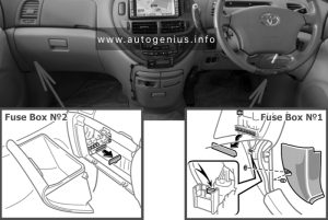
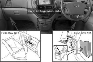
The main fuse panel is in the instrument panel, below the steering column.

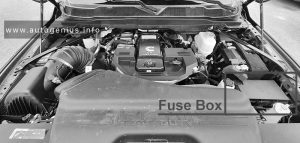
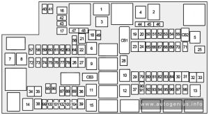
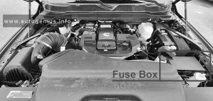
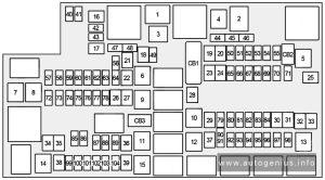
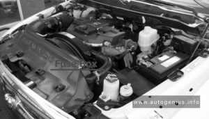
Engine Compartment Fuse Box

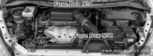
Access to these fuses is gained by removing the snap-on cover.

Fuse Box Diagrams

VY (MY2003)

Cabin fuses and relays
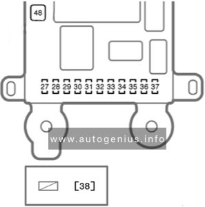
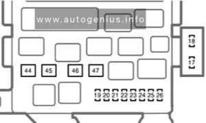
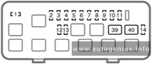
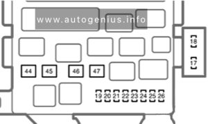
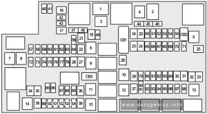
Holden Cross 8 (VY; MY2003) - fuse box diagram - passenger compartment
Holden Cross 8 (VY; MY2003) – fuse box diagram – passenger compartment
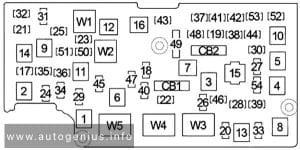
Under-hood fuses and relays
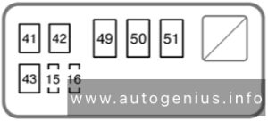
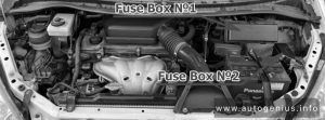
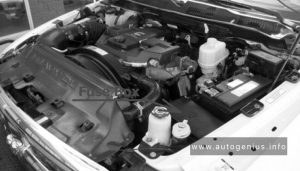
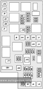
Holden Cross 8 (VY; MY2003) - fuse box diagram - engine compartment
Holden Cross 8 (VY; MY2003) – fuse box diagram – engine compartment

VY (MY2005)

Cabin fuses and relays
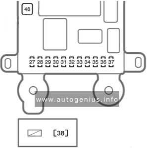
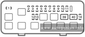
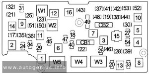
Holden Cross 8 (VY; MY2005) - fuse box diagram - passenger compartment
Holden Cross 8 (VY; MY2005) – fuse box diagram – passenger compartment
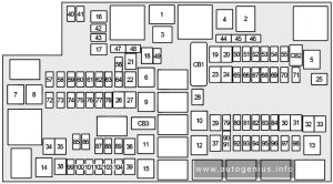
Under-hood fuses and relays
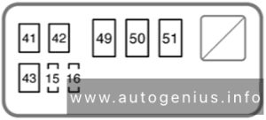
Holden Cross 8 (VY; MY2005) - fuse box diagram - engine compartment
Holden Cross 8 (VY; MY2005) – fuse box diagram – engine compartment

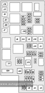
VZ (MY2005-2006)

Wagon
Holden Cross 8 (VZ; MY2005-2006) - fuse box diagram - wagon
Holden Cross 8 (VZ; MY2005-2006) – fuse box diagram – wagon
Crew cab and regular cab
Holden Cross 8 (VZ; MY2005-2006) - fuse box diagram - crew cab and regular cab
Holden Cross 8 (VZ; MY2005-2006) – fuse box diagram – crew cab and regular cab

WARNING: Terminal and harness assignments for individual connectors will vary depending on vehicle equipment level, model, and market.

Holden Adventra (VY, VZ; 2003 – 2006) – fuse box diagram

Holden Adventra (VY, VZ; 2003 – 2006) – fuse box diagram

Year of production: 2003, 2004, 2005, 2006

Passenger Compartment Fuse Box

The main fuse panel is in the instrument panel, below the steering column.

Engine Compartment Fuse Box

Access to these fuses is gained by removing the snap-on cover.

Fuse Box Diagrams

VY (MY2003)

Cabin fuses and relays
Holden Adventra (VY; MY2003) - fuse box diagram - passenger compartment
Holden Adventra (VY; MY2003) – fuse box diagram – passenger compartment
Under-hood fuses and relays
Holden Adventra (VY; MY2003) - fuse box diagram - engine compartment
Holden Adventra (VY; MY2003) – fuse box diagram – engine compartment

VY (MY2005)

Cabin fuses and relays
Holden Adventra (VY; MY2005) - fuse box diagram - passenger compartment
Holden Adventra (VY; MY2005) – fuse box diagram – passenger compartment
Under-hood fuses and relays
Holden Adventra (VY; MY2005) - fuse box diagram - engine compartment
Holden Adventra (VY; MY2005) – fuse box diagram – engine compartment

VZ (MY2005-2006)

Wagon
Holden Adventra (VZ; MY2005-2006) - fuse box diagram - wagon
Holden Adventra (VZ; MY2005-2006) – fuse box diagram – wagon
Crew cab and regular cab
Holden Adventra (VZ; MY2005-2006) - fuse box diagram - crew cab and regular cab
Holden Adventra (VZ; MY2005-2006) – fuse box diagram – crew cab and regular cab

WARNING: Terminal and harness assignments for individual connectors will vary depending on vehicle equipment level, model, and market.

Holden Acadia (2018 – 2020) – fuse and relay box diagram

Holden Acadia (2018 – 2020) – fuse and relay box diagram

Year of production: 2018, 2019, 2020


The Holden Acadia (AC), a mid-size crossover SUV, was manufactured between 2018 and 2020. This article provides fuse box diagrams for the 2018, 2019, and 2020 Holden Acadia models, details the locations of the fuse panels within the vehicle, and explains the function and layout of each fuse and relay.


Passenger Compartment Fuse Box

Fuse Box Location

The instrument panel fuse block is inside the centre console on the right-hand side of the vehicle.

Holden Acadia (2018 - 2020) - fuse and relay box location - passenger compartment
Holden Acadia (2018 – 2020) – fuse and relay box location – passenger compartment


Fuse Box Diagram

Holden Acadia (2018 - 2020) - fuse and relay box diagram - passenger compartment
Holden Acadia (2018 – 2020) – fuse and relay box diagram – passenger compartment


Assignment of the fuses in passenger compartment

Usage
F1 Body control module 6
F2 Diagnostic link / Central gateway module
F3 Electric steering column lock
F4
F5
F6 Heating, ventilation, and air conditioning
F7 Body control module 3
F8
F9 Right front heated seat
F10 Airbag / Seat belt
F11
F12 Amplifier / Noise control module
F13 Body control module 7
F14 Left front heated seat
F15
F16 Sunroof
F17
F18 Instrument cluster
F19 Body control module 1
F20 Rear seat entertainment
F21 Body control module 4
F22 Infotainment USB data / Aux jack
F23 Body control module 2
F24 USB charger / Wireless charging
F25 Ultrasonic park aid
F26 CIM
F27
F28 Heating, ventilation, and air conditioning display
F29 Radio
F30 Steering wheel adjustment controls
F31 2018-2019: Front blower
2020: Electronic brake control module electric brake booster
F32 DC AC inverter
F33 Driver power seat
F34 Passenger power seat
F35 Battery IEC 1 feed
F36 Electric power steering
F37 Rear seat entertainment / USB charge / Wireless charging module / Auxiliary power outlet
F38 Body control module 8
F39
Circuit Breakers
F40
F41
F42 Auxiliary power outlet / Lighter

Engine Compartment Fuse Box

Fuse Box Location

Holden Acadia (2018 - 2020) - fuse and relay box location - engine compartment
Holden Acadia (2018 – 2020) – fuse and relay box location – engine compartment


Fuse Box Diagram

Holden Acadia (2018 - 2020) - fuse and relay box diagram - engine compartment
Holden Acadia (2018 – 2020) – fuse and relay box diagram – engine compartment


Assignment of the fuses in the engine compartment

Usage
F1 Antilock brake system
F2 Starter 1
F3 DC/DC transformer 1
F4
F5 DC/DC transformer 2
F6
F7 2018-2019: Electronic brake control module eboost
2020: Front blower
F8 Starter 3
F9
F10 2020: Brake lamp trailer
F11
F12 Front wiper
F13 2020: Starter 2
F14
F15 Rear wiper
F16
F17
F18
F19
F20
F21
F22 Electronic brake control module
F23 Parking / Trailer lamps
F24 Right trailer stop lamp / lndicator lamp
F25 Steering column lock
F26
F27 Left trailer stop lamp / Indicator lamp
F28
F29
F30 Washer pump
F31 Spare / Headlamp low-beam right
F32 Headlamp low-beam left
F33 Headlamp hi-beam shutter / Fog lamps
F34 Horn
F35
F36 Headlamp low-beam right / Headlamp high-beam left
F37 Spare / Headlamp high-beam right
F38 Automatic headlamp levelling motor
F39 Transmission control module
F40 Left rear bus electrical centre / Ignition
F41 Instrument cluster
F42 Heating, ventilation, and air conditioning / Central gateway module run/crank
F43 Reflective light alert display
F44 Electronic brake control module eboost run/crank
F45
F46
F47
F48
F49 Interior rear view mirror / Trailer
F50 Fuel system control module / Fuel tank zone module run / crank
F51 Heated steering wheel
F52 Air conditioning clutch
F53
F54 Coolant pump
F55
F56
F57 Engine control module / lgnition
F58 Transmission control module / lgnition
F59 Engine control module battery
F60
F61 O2 sensor 1 / Aero shutter / Mass air flow sensor
F62 Engine control module – odd
F63 O2 sensor 2
F64 Engine control module – even
F65 Engine control module powertrain 1
F66 Engine control module powertrain 2
F67 Engine control module powertrain 3
F68
F69
F70
F71
F72
F73
F74
F75
F76
F77
Relays
K1 Starter 1
K2 Run/Crank
K3 Starter 3
K4
K5
K6 Coolant pump
K7 Engine control module
K8 Air conditioning
K9 2020: Brake trailer lamp
K10 2020: Starter 2

Rear Compartment Fuse Box

Fuse Box Location

The rear fuse panel is located below the left-hand side trim panel in the rear compartment.

Holden Acadia (2018 - 2020) - fuse and relay box location - rear compartment
Holden Acadia (2018 – 2020) – fuse and relay box location – rear compartment


Fuse Box Diagram

Holden Acadia (2018 - 2020) - fuse and relay box diagram - rear compartment
Holden Acadia (2018 – 2020) – fuse and relay box diagram – rear compartment


Assignment of the fuses in the rear compartment

Usage
F1
F2 Trailer battery
F3
F4 Rear blower
F5 Rear drive control 1
F6
F7 Right window
F8 Rear demister
F9 Left window
F10
F11 Trailer reverse
F12
F13
F14
F15
F16
F17
F18
F19
F20 Glove box door / Trailer brake lamp
F21
F22
F23
F24
F25
F26 Trailer brake
F27 Driver ventilated seat / Lumbar
F28 Passive entry / Passive start
F29
F30 Canister vent
F31
F32 Heated mirror
F33
F34 Liftgate module
F35 Fuel system control module / Fuel tank zone module
F36 Passenger ventilated seat / Lumbar
F37
F38 Window module
F39 Rear closure
F40 Memory seat module
F41 Automatic occupancy sensor
F42
F43
F44
F45 Liftgate motor
F46 Rear heated seats
F47
F48
F49
F50
F51
F52 Rear drive control 2 / Active dampening system module
F53 Video
F54 External object calculating / Side blind zone alert
F55
F56 Universal garage door opener / Rain sensor
F57 Theft deterrent
Circuit Breakers
CB1
CB2
CB3 Rear auxiliary power outlet
Relays
K1
K2


WARNING: Terminal and harness assignments for individual connectors will vary depending on vehicle equipment level, model, and market.

GMC Yukon (2021 – 2022) – fuse box diagram

GMC Yukon (2021 – 2022) – fuse box diagram

Year of production: 2021, 2022

Engine Compartment Fuse Block

The engine compartment fuse block is in the engine compartment, on the driver side of the vehicle.

GMC Yukon - fuse box diagram - engine compartment
GMC Yukon – fuse box diagram – engine compartment
Usage
1
2
3
4
6 Exterior Lighting Module 7
7 Exterior Lighting Module 4
8
9 Exterior Lighting Module 5
10 Exterior Lighting Module 6
11 Spare
12
13 Washer Front
14 Washer Rear
15 Rear Electrical Center 2
16 Power Sounder
17 Spare
19 DC/AC Inverter
20 IECR 2
21
22 IECL 2
24 Electronic Brake Control Module
25 Rear Electrical Center 1
26 Camera Wash
27 Horn
28 Headlamp Right
29 Headlamp Left
30 Exterior Lighting Module 3
31 Exterior Lighting Module 1
32
33 Not R/C
34
37 On Board Diagnostics (OBD) Body
38 MISC Body
39 Upfitter
40 MISC Instrument Panel (IP)
41 Trailer Parking Lamps
42 Right Taillamp
44 Trailer Tow
45 Secondary Axle Motor
46 Engine Control Module (ECM) Ignition
47 OBD Engine
48
49 Telematics Control Module
50 A/C Clutch
51 Transfer Case Control Module
52 Front Wiper
53
54 Left Taillamps
55 Trailer Back-up Lamp
56 Semi Active Damping System
57 Spare
58 Starter Motor
60 Active Fuel Management 1
61 Automatic Lamp Control (ALC) Main
62 Integrated Chassis Control Module/ Canister Vent Solenoid/ Diesel Exhaust Fluid
63 Trailer Brake
65 Auxiliary Underhood Electrical Center
66 Left Cool Fan Motor
67 Active Fuel Management 2
68 Automatic Lamp Control (ALC) Motor
69 Starter Pinion
71 Cool Fan Motor Lower
72 Right Cool Fan Motor/ Lower
73 Left Trailer Stop Turn Lamp
74 Trailer Interface Module 2
75 Diesel Exhaust Fluid Controller
76 ELEC RNG BDS
78 Engine Control Module
79
80 Cabin Cool Pump 17W
81 Right Trailer Stop Turn Lamp
82 Trailer Interface Module 1
83 Fuel Tank Zone Module
84 Trailer Battery
85 Engine
86 Engine Control Module
87 Injector B Even
88 O2 B Sensor
89 O2 A Sensor
90 Injector A Odd
91 Engine Control Module (ECM) Throttle Control
92 Cool Fan Clutch AERO Shutter
Relays
5
18 DC/AC Inverter
23
35 Park Lamp
36 Run/Crank
43 Secondary Axle Motor
59 A/C Clutch
64 Starter Motor
70 Starter Pinion
77 Powertrain

Passenger Compartment Fuse Box

The right instrument panel fuse block access door is on the passenger side edge of the instrument panel.

GMC Yukon - fuse box diagram - passenger compartment
GMC Yukon – fuse box diagram – passenger compartment
Usage
F1 Right Door
F2 Left Door
F3 Universal Garage Door Opener (UGDO)/ OnStar Hands-free Calling (OHC)/ Camera
F4 Body Control Module 2
F5 Displays
F6 Front Blower
F8 Left Door Pane
F10 Tilt/Column Lock
F11 USB/ Data Link Connector (DLC)
F12 Central Gateway Module (CGM)/ Onstar
F14 Right Door Panel
F17 Steering Wheel Control
F18 Active Vibration Module 1
F19
F20
F21
F22 Heated Wheel
F23
F24
F25 Search Engine Optimization (SEO)/ UPFITTER
F26 USB/ Search Engine Optimization (SEO) Retained Accessory Power (RAP)
F27 Auxiliary Power Outlet (APO)/ Retained Accessory Power
F28 Spare
F30 Sensing and Diagnostic Module/ Automatic Occupant Sensing
F31 Body Control Module 3
F32 Center Stack Module (CSM)/USB
F33 Body Control Module 4
F34 Out of Park
F40
F41
F42 Electric Park Brake Switch
F43 Road Side Equipment
F44 Active Vibration Module 2
F45 Radio Module
F46 Body Control Module 1A
F47
F48 Telematics Control Module
F49 Body Control Module 1
F50 Driver Monitoring System
F51
F52
F53
F54 Sunroof
F55 Auxiliary Power Outlet 3
F56 Direct Current/ Direct Current Converter Battery 1
F57 Direct Current/ Direct Current Converter Battery 2
F58 Spare
F59
CB01 Auxiliary Power Outlet 1
CB02 Auxiliary Power Outlet 2
Relays
K1
K2 Retain Accessory Power/ Accessory 1
K4 Retain Accessory Power/ Accessory 2
K5

Rear Compartment Fuse Box

The rear compartment fuse block is behind the access panel on the left side of the compartment.

GMC Yukon - fuse box diagram - rear compartment
GMC Yukon – fuse box diagram – rear compartment
Usage
F1 Remote Function Actuator
F2 Wireless Charging Module
F3 Heated Seat Module Row 1 (Battery 1)
F4 Memory Seat Module (MSM) Driver
F5
F6
F7 Amplifier Auxiliary 2
F8
F9 Search Engine Optimization Upfitter 2
F10 Motor Seatbelt Passenger
F11 Power Folding Seat Row 2
F12 GBS
F13
F14
F15 Heated Seat Module Row 1 (Battery 2)
F16 Right Hand Cinch Latch
F17 Memory Seat Module Passenger
F18 Rear Wiper
F19 Motor Seatbelt Driver
F20 Rear Defogger
F21
F22 Rear HVAC Display Control
F23 External Object Calculation Module
F24 Amplifier Auxiliary 3
F25 OBS DET
F26 Rear Drive Control Module
F27 Amplifier Auxiliary 1
F28 Video Processing Module
F29
F30
F31 Amplifier
F32
F33 Integrated Chassis Control Module
F34 Heated Seat Module Row 2
F35 HFCR
F36 Exterior Lighting Module
F37
F38 Power Slide Console
F39
F40
F41
F42
F43 Universal Park Assist
F44
F45 Adaptive Forward Lighting/ Automatic Headlamp Leveling
F46 Rear HVAC Blower Motor
F47 Left Hand Cinch Latch
F48 Power Seat Recline Module
F49 Lift Glass
F50 Driver Power Seat
F51 Power Liftgate Module
F52 Passenger Power Seat
Relays
K53
K54
K55 Lift Glass


WARNING: Terminal and harness assignments for individual connectors will vary depending on vehicle equipment level, model, and market.

GMC Sierra (2021 – 2022) – fuse box diagram

GMC Sierra (2021 – 2022) – fuse box diagram

Year of production: 2019, 2020

Engine Compartment Fuse Block

The engine compartment fuse block is in the engine compartment, on the driver side of the vehicle.

GMC Sierra - fuse box diagram - engine compartment
GMC Sierra – fuse box diagram – engine compartment
Usage
1 High-beam left
2 High-beam right
3 Headlamp left
4 Headlamp right
6
7
8 Fog Lamp
9
10
11 Police Upfitter
12
13 Washer Front
14 Washer Rear
15
16
17 IECL 1
19 DC/AC Inverter
20 IECR 2 (LD)/EBCM 2 (HD) – Electronic Brake Control Module
21
22 IECL 2
24 Electronic Brake Control Module 1
25
26
27 Horn
28
29
30
31
32 Rear Window Defogger
33 Heated Mirror
34 Parking Lamp Left
37
38
39
40 Misc ignition
41 Trailer Parking Lamp
42 Park Lamp Right
44
45
46 Engine Control Module Ignition
47 Transmission Control Module Ignition
48
49 Transmission Control Module
50 A/C Clutch
51 Transfer Case Control Module
52 Front Wiper
53 Center High-mounted Stop Lamp
54 Trailer Reverse Lamp
55 Trailer Back-up Lamp
56 Semi Active Damping System
57 Side Blind Zone Alert
58 Starter motor (LD and HD DSL)
60 Active Fuel Management 1
61 Vehicle Emission System
62 Integrated Chassis Control Module/CVS – Canister Vent Solenoid
63 Trailer Battery
65 Auxiliary Underhood Electrical Center
66 Cooling Fan Motor Left
67 Active Fuel Management 2
68
69 Starter Pinion (LD)/ Starter Motor (HD Gas)
71 Cooling Fan
72 Cooling Fan Right/Lower
73 Trailer Stop/Turn Lamp Left
74 Trailer Interface Module 1
75 Diesel Exhaust Fluid Controller
76 Electric RNG BDS
78 Engine Control Module
79 Auxiliary Battery
80 Cabin Cooling Pump
81 Trailer Stop/Turn Lamp Right
82 Trailer Interface Module 2
83 Fuel Tank Zone Module
84 Trailer Brake
85 Engine
86 Engine Control Module
87 Injector B Even
88 O2 B Sensor
89 O2 A sensor
90 Injector A Odd
91 Engine Control Module Throttle Control
92 Aeroshutter
Relays
5 Headlamp
18 DC/AC inverter
23 Rear window defogger
35 Parking lamp
36 Run/Crank
43
59 A/C clutch
64 Starter Motor (LD & HD DSL)
70 Starter Pinion (LD) / Starter Motor (HD Gas)
77 Powertrain
77 Powertrain


Instrument Panel Fuse Block (Left)
GMC Sierra - fuse box diagram - instrument panel (left)
GMC Sierra – fuse box diagram – instrument panel (left)
Usage
F1 Rear Heated Seats Left/ Right
F3
F4
F5 Multifunction End Gate
F6 Heated and Ventilated Seats Left/Right
F8
F9 Passive Entry Passive Start/ Spare
F10
F11
F12 Passenger Power Seat
F13 Export Power Take Off/ Special Equipment Option 1
F14
F15
F16 Amplifier
F17
F18
F20 Endgate
F22 Rear Sliding Window
F23
F24
F25
F26
F27
CB1
Relays
K1 Rear Sliding Window Open
K2 Rear sliding Window Close
K3 Multifunction End Gate Major 1
K4 Multifunction End Gate Major 1
K5 Multifunction End Gate Minor 2
K6 Multifunction End Gate Minor 2
K7
K8
K6 MFEG major 2
K7 Anti-theft
K8 Not Used
Instrument Panel Fuse Block (Right)
GMC Sierra - fuse box diagram - instrument panel (right)
GMC Sierra – fuse box diagram – instrument panel (right)
Usage
F1 Right Doors
F2 Left Doors
F3 Universal Garage Door Opener
F4
F5
F6 Front Blower
F8 Lumbar Switch
F10 Body Control Module 6/ Body Control Module 7
F11 Seat/Column Lock Module
F12 Body Control Module 3/ Body Control Module 5
F14 Mirrors/Windows Module
F17 Steering Wheel Controls
F18 Video Processing Module/ Obstacle Detection
F19 Discrete Logic Ignition Switch (DLIS)
F20 Ventilated Seats
F21 NOT R/C
F22 Heated Steering Wheel
F23 MISC R/C
F24 2021: Instrument panel cluster ignition/Overhead
2022: Power Take Off/Reflective Light Auxiliary Display/ Instrument Panel Cluster/ Central Gateway Module/ Inside Rear View Mirror/ Overhead Console Module Ignition
F25 Heating, Ventilation, and Air Conditioning Ignition/ Heating, Ventilation, and Air Conditioning Auxiliary
F26 USB Ports/Special Equipment Option Retained Accessory Power
F27 Accessory Power Outlet/ Retained Accessory Power
F28 Accessory Power Outlet/ Battery
F30 Sensing and Diagnostic Module/Parking Brake
F31 Body Control Module 4
F32 Special Equipment Option/ Data Link Connection
F33 Body Control Module 8
F34 Cargo Lamp
F40 Central Gateway Module (CGM)
F41 Infotainment 1
F42 Telematics Connectivity Platform
F43
F44 2021: Active vibration management
F45 Body Control Module 2
F46 Heating, Ventilation, and Air Conditioning/Battery 1
F47 Instrument Panel Cluster/ Battery
F48 Transmission Control Module
F49 Body Control Module 1
F50
F51 Battery 1
F52 Battery 2
F53
F54 Sunroof
F55 Driver Power Seat
F56 DC DC TRANS 1
F57 DC DC TRANS 2
F58 Infotainment 2
CB1 Accessory Power Outlet 2
CB2 Accessory Power Outlet 1/ Cigarette Lighter
CB3 2021: Accessory power outlet 3
CB4 2021: Accessory power outlet 4
Relays
K1 Run/Crank
K2 Retained Accessory Power/ Accessory 1
K4 2021: Retained accessory power/ Accessory 2
K5
K1 Run/Crank
K2 Retained accessory power/Accessory 1
K4 Retained accessory power/Accessory 2
K5 Not Used

WARNING: Terminal and harness assignments for individual connectors will vary depending on vehicle equipment level, model, and market.

GMC Sierra (2019 – 2020) – fuse box diagram

GMC Sierra (2019 – 2020) – fuse box diagram

Year of production: 2019, 2020

Engine Compartment Fuse Block

The engine compartment fuse block is in the engine compartment, on the driver side of the vehicle.

GMC Sierra - fuse box diagram - engine compartment
GMC Sierra – fuse box diagram – engine compartment
Usage
1 High-beam left
2 High-beam right
3 Headlamp left
4 Headlamp right
6 TIM
7 Not Used
8 Fog lamp
9 VKM
10 Not Used
11 Police upfitter
12 Not Used
13 Washer front
14 Washer rear
15 MSB driver
16 Not Used
17 IECL 1
19 DC/AC inverter
20 2019: IECR 2
2020: IECR 2 (LD) / EBCM2 (HD)
21 MSB pass
22 IECL 2
24 2019: Eboost 1
2020: EBCM 1
25 REC
26 Not Used
27 Horn
28 Not Used
29 Not Used
30 Not Used
31 Not Used
32 Rear window defogger
33 Heated mirror
34 Parking lamp left
37 Euro trailer
38 TIM
39 Not Used
40 Misc ignition
41 Trailer parking lamp
42 Park lamp right
44 Not Used
45 Second fuel pump
46 Engine control module ignition
47 Transmission control module ignition
48 Not Used
49 Transmission control module
50 A/C clutch
51 Transfer case control module
52 Front wiper
53 Center high-mounted stop lamp
54 Trailer reverse lamp
55 Trailer back-up lamp
56 SADS
57 TTPM
58 2019: Starter motor
2020: Starter motor (LD & HD DSL)
60 Active fuel management 1
61 VES
62 Integrated chassis control module/CVS
63 Trailer battery
65 Auxiliary underhood electrical center
66 Cooling fan motor left
67 Active fuel management 2
68 Not Used
69 2019: Starter pinion
2020: Starter Pinion (LD) / Starter Motor (HD Gas)
71 Cooling fan
72 Cooling fan right
73 Trailer stop/turn lamp left
74 TIM
75 DEFC
76 Electric RNG BDS
78 Engine control module
79 Auxiliary battery
80 Cabin cooling pump
81 Trailer stop/turn lamp right
82 TIM
83 FTZM
84 Trailer brake
85 ENG
86 Engine control module
87 Injector B even
88 O2 B sensor
89 O2 A sensor
90 Injector A odd
91 Engine control module throttle control
92 Cool fan clutch
Relays
5 Headlamp
18 DC/AC inverter
23 Rear window defogger
35 Parking lamp
36 Run/Crank
43 Second fuel pump
59 A/C clutch
64 2019: Starter motor.
2020: Starter Motor (LD & HD DSL) / Cool Fan Clutch (HD Gas)
70 2019: Starter pinion.
2020: Starter Pinion (LD) / Starter Motor (HD Gas)
77 Powertrain


Instrument Panel Fuse Block (Left)
GMC Sierra - fuse box diagram - instrument panel (left)
GMC Sierra – fuse box diagram – instrument panel (left)
Usage
F1 Rear heated seats left/right
F3 Euro trailer
F4 Not Used
F5 Front Bolster
F6 Heated and cooled seats left/right
F8 Rear seat entertainment/Theft deterrent
F9 Passive entry/Passive start/Driver seat module
F10 Not Used
F11 Sunshade
F12 Passenger power seat
F13 Export power take off/ Special equipment option 1
F14 Not Used
F15 Not Used
F16 AMP
F17 MFEG
F18 Not Used
F20 Endgate
F22 Rear sliding window
F23 Not Used
F24 Not Used
F25 Not Used
F26 Not Used
F27 Not Used
Circuit Breakers
CB1 Not Used
Relays
K1 Rear sliding window open
K2 Rear sliding window close
K3 MFEG major 1
K4 MFEG minor 1
K5 MFEG minor 2
K6 MFEG major 2
K7 Anti-theft
K8 Not Used
Instrument Panel Fuse Block (Right)
GMC Sierra - fuse box diagram - instrument panel (right)
GMC Sierra – fuse box diagram – instrument panel (right)
Usage
F1 Right doors
F2 Left doors
F3 Universal remote system
F4 Not Used
F5 Not Used
F6 Front blower
F8 Lumbar switch
F9 Not Used
F10 Body control module 6/Body control module 7
F11 Seat/CLM
F12 Body control module 3/Body control module 5
F14 Mirrors/Windows module
F17 Steering wheel controls
F18 VPM/OBS DET
F19 DLIS
F20 Cooled seats
F21 NOT R/C
F22 Heated steering wheel
F23 MISC R/C
F24 Instrument panel cluster ignition/ Overhead
F25 Heating, ventilation, and air conditioning ignition/Heating, ventilation, and air conditioning auxiliary
F26 USB ports/Special equipment option retained accessory power
F27 Accessory power outlet/retained accessory power
F28 Accessory power outlet/Battery
F30 Sensing and diagnostic module/ Parking brake
F31 Body control module 4
F32 Special equipment option/Data link connection
F33 Body control module 8
F34 Cargo lamp
F40 CGM
F41 Infotainment 1
F42 TCP
F43 Not Used
F44 AVM
F45 Body control module 2
F46 Heating, ventilation, and air conditioning/ Battery 1
F47 Instrument panel cluster/Battery
F48 Transmission control module
F49 Body control module 1
F50 Not Used
F51 Battery 1
F52 Battery 2
F53 Not Used
F54 Sunroof
F55 Driver power seat
F56 DC DC TRANS 1
F57 DC DC TRANS 2
F58 Infotainment 2
Circuit Breakers
CB1 Accessory power outlet 2
CB2 Accessory power outlet 1/Cigarette Lighter
CB3 Accessory power outlet 3
CB4 Accessory power outlet 4
Relays
K1 Run/Crank
K2 Retained accessory power/Accessory 1
K4 Retained accessory power/Accessory 2
K5 Not Used

WARNING: Terminal and harness assignments for individual connectors will vary depending on vehicle equipment level, model, and market.

GMC Savana (2018- 2022) – fuse box diagram

GMC Savana (2018- 2022) – fuse box diagram

Year of production: 2011, 2012, 2013, 2014, 2015, 2016, 2017

Engine Compartment Fuse Block

The fuse block is located in the engine compartment on the driver side of the vehicle.

GMC Savana - fuse box - engine compartment
GMC Savana – fuse box – engine compartment
Usage
1 ABS motor
2 ABS module
3 Right trailer stoplamp/ Turnlamp
4
5
6 Fuel system control module/ Ignition
7 Body control module 5
8 Body control module 7
9 Body control module 4
10 Instrument cluster
11 Trailer wiring
12
13 Interior Rear Vision Camera Module
14 Windshield washer
16 Horn
17 Transmission
18 A/C
19 Engine control module battery
20 Cutaway/Left stoplamp/Turnlamp
21 Left trailer stoplamp/Turnlamp
22 Cutaway/Right stoplamp/Turnlamp
23 2021-2022: NOX Sensor (Diesel Only)
24 Fuel pump
25 Auxiliary power outlet
26 Body control module 3
27 Special equipment option
28 Airbag
29 Steering wheel sensor
30 Engine control module Ignition
31 Transmission control module/ Ignition
32 Transmission control module 1 battery/ Engine control module battery power (gas 6 cyl)
33 Rear parking aid module
34 2021-2022: NOX Sensor (Diesel Only)
35 2021-2022: Fuel Heater Control Module (Diesel Only)
36 Fuel system control module battery
41 Transmission control 2 module battery power
42 Trailer wiring
43 2021-2022: Electro Viscous Fan Clutch (Diesel Only)
44 Starter solenoid
45 Engine control module/ Powertrain
46 AC DC inverter
47 Cooling fan – low
51 Left high-beam headlamp
52 Right high-beam headlamp
53 Left low-beam headlamp
54 Right low-beam headlamp
55 Wipers
56 Canister vent solenoid
58 Body control module 2
59 Body control module 1
61 Engine Oil Solenoid/ Crankcase Vent Heater (Diesel Only)
62 O2 sensor 2
63
64 Mass air flow/ Canister vent
65 Ignition/ Injectors – odd
66 Daytime running lamps 2
67 Daytime running lamps 1
68 Auxiliary stoplamps
69 External power for trailer
70 Upfitter stoplamps
71 Fuel heater/ Flex fuel sensor
72 Body control module 6
73 Lighter/ Data link connector
74 Front blower
75 2018: V6 fuel injectors
2019-2022: Engine Control Module
76 2021-2022: Soot Sensors (Diesel Only)
77 O2 sensor 1
78 Engine control module/ Powertrain
79 Ignition/ Injectors – even
Relays
15 Run/Crank
37 2021-2022: NOX Sensor (Diesel Only)
38 Fuel pump
39 Crank
40 A/C compressor
48 2021-2022: Electro Viscous Fan Clutch (Diesel Only)
49 Powertrain
50
57 Cooling fan – low
60 Cooling fan control


Auxiliary Fuse Block

GMC Savana - fuse box diagram - auxiliary fuse box
GMC Savana – fuse box diagram – auxiliary fuse box
Usage
MR-1 Upfitter 1
MR-2 Upfitter 2
MR-3 Upfitter power control
MR Rel 1 Upfitter 1
MR Rel 2 Upfitter 2


Mega Fuse Hölder

GMC Savana - fuse box diagram - mega fuse holder
GMC Savana – fuse box diagram – mega fuse holder
Usage
1 Starter motor


Passenger compartment

GMC Savana - fuse box - passenger compartment
GMC Savana – fuse box – passenger compartment
Usage
F1
F2 Steering wheel sensor
F3 Auxiliary parking lamps
F4 Front parking lamps
F5 Trailer parking lamps
F6 Upfitter/Parking lamps
F7 Right rear parking lamp
F8 Left rear parking lamp
F9 2018: Exterior rear mirror switch/ Door lock-unlock control upfitter
2019-2021: Exterior rear mirror switch/ Door lock-unlock control upfitter/ Front camera module
2022: Outside View Mirror Switch/ Front Camera Module
F10 Airbag/Automatic occupant sensing
F11 OnStar
F12 2018-2020: ECM batt
F13 HVAC 2
F14 HVAC 1
F15 2020-2022: Reflected LED display
F16 Upfitter 1
F17 Exterior rearview heated mirrors
F18 Rear window defogger
F19 Compass
F20 Radio/Chime/ SiriusXM satellite radio
F21 Remote function actuator/Tire pressure monitor
F22 Ignition switch/ Discrete logic ignition sensor / Pass Key 3
F23 Instrument cluster
F24
F25 HVAC control
F26 Auxiliary/Trailer reverse lamps
F27 Reverse lamps
F28 Upfitter 2/ Reading lamps
F29 Rear blower
F30 Upfitter/ Courtesy lamps
F31 Front door lock
F32 Rear door lock
F33 Cargo door unlock
F34 Passenger door unlock
F35 Rear passenger door unlock
F36 Driver door lock
F37
F38
CB1 Power seats (Circuit Breaker)
CB2 Power windows (Circuit Breaker)
Relays
K1 Run
K2
K3 Parking lamps
K4 Upfitter 2
K5 Rear defogger
K6


WARNING: Terminal and harness assignments for individual connectors will vary depending on vehicle equipment level, model, and market.

GMC Hummer EV (2022 – 2023) – fuse box diagram

GMC Hummer EV (2022 – 2023) – fuse box diagram

Year of production: 2022, 2023

Left Instrument Panel Fuse Block

The instrument panel fuse block is on the driver side of the instrument panel, between the steering wheel and the door.

GMC Hummer EV - fuse box diagram - left instrument panel
GMC Hummer EV – fuse box diagram – left instrument panel
Usage
F01 Driver Power Seat
F02 Sensing and Diagnostic Module/ Automatic Occupant Sensing
F03 Virtual Key System/ Trailer Tow Power Module/ Short Range Radar
F04 Body Control Module 1
F05 Exterior Lighting Module 5
F06 Minor End Gate
F07 Spare
F08 Telematics Control Platform
F09 Lumbar
F10 Wireless Charger Module / Display
F11 2nd Row Heated Seat / 2nd Row Heated Seat 2
F12 Out of Park
F13 Video Process Module / External Object Calculation Module
F14 Spare
F15 Spare
F16 Tonneau
F17 Vehicle Extension Control Module
F18 Spare
F19 Spare
F20 Memory Seat Module Driver
F21 Designated Seating Position / Heated Seat Module Row 1
F22 Spare
F23 End Gate Motor
F24 Traction Power Inverter Module 1
F25 Spare
F26 Traction Power Inverter Module 2
F27 Heated Seat Module Row 1
F28 Exterior Lighting Module 7
F29 Obstacle Detection
F30 Major End Gate Motor Ground
F31 Exterior Lighting Module 2
F32 Remote Function Actuator
F33 Motor (ENDGATE MTR 2)
F34 Traction Power Inverter Module 3
F35 Amplifier
F36 Passenger Power Seat
F37 Spare
F38 Spare
F39 Right Hand Power Window
F40 Left Hand Power Window
CB01 Spare
CB02 Spare

Right Instrument Panel Fuse Block

The instrument panel fuse block is located behind the glove box.

GMC Hummer EV - fuse box diagram - right instrument panel
GMC Hummer EV – fuse box diagram – right instrument panel
Usage
F01 Front Blower Motor
F02 Steering Column Adjust Module
F03 Electronic Transmission Range System/ Steering Column Lock
F04 Spare
F05 Body Control Module 2
F06 Body Control Module 4
F07 CLOCK SPRING
F08 Trailer Brake Control Switch/ Electric Park Brake
F09 Spare
F10 Displays / Night Vision Module
F11 High Definition Localization Module / Central Gateway Module
F12 Steering Column Lock
F13 Traction Power Inverter Module 3 / Data Link Connection
F14 Body Electric / Trailer Interface Module
F15 Driver INFO
F16 Spare
F17 Traction Power Inverter Module 1 / Traction Power Inverter Module 2
F18 Body / Instrument Panel 2
F19 Vehicle Integration Control Module/ Traction Power Inverter Module
F20 Spare
F21 Spare
F22 Spare
F23 eTrunk Auxiliary Power Outlet
F24 Rain Sensor/ Front Camera Module
F25 Auxiliary USB
F26 Exterior Lightning Module 6
F27 Center Stack Module/Auxiliary Jack
F28 Spare
F29 Driver Monitoring System
F30 Spare
F31 Body Control Module 3
F32 Heating Steering Wheel Module
F33 Spare
F34 Spare
F35 Module-power Tailgate (Swing-gate)
F36 Rear HVAC Blower Motor
F37 Spare
F38 Spare
F39 SWING GATE MDL 2
F40 Spare
CB01 Auxiliary Power Outlet Center Console
CB02 Spare

Underhood Compartment Fuse Box

The Underhood Compartment Fuse Block is under a cover and side extensions/ shields in the underhood compartment.

GMC Hummer EV - fuse box diagram - underwood compartment
GMC Hummer EV – fuse box diagram – underwood compartment
Usage
F01 Integrated Chassis Control Module
F02 2022: Spare
2023: Primary Coolant Valve/ Secondary Coolant Valve
F03 Spare
F04 Spare
F05 Spare
F06 Air Conditioning Electric Compressor/ Coolant Valve
F07 Energy Storage System Coolant Pump
F08 Spare
F09 Power Electronics Coolant Pump
F10 Spare
F11 Spare
F12 Rear Glass Open
F13 Trailer Brake Connector
F14 Spare
F15 Charge Port Door Lamp / Automatic Level
Control Main
F16 Spare
F17 Exterior Lighting Module 1
F18 Tail Lamp Left / Suspension Control Module
F19 Instrument Panel Fuse Block Left 2
F20 Spare
F21 Spare
F22 Condensing Heating Flow Valve Motor
F23 Tail Lamp Right / Vehicle Integrated Control Module
F24 Spare
F25 Spare
F26 Spare
F27 2022: Primary Coolant Valve/ Secondary Coolant Valve
2023: Park Lamp
F28 2022: Park Lamp
2023: Spare
F29 Spare
F30 Trans Oil Pump 1
F31 Spare
F32 Trans Oil Pump 2
F33 Reverse Lamp
F34 Trailer Interface Module Primary
F35 Spare
F36 Traction Power Inverter Module 1
F37 Spare
F38 Trail Stop/ Turn Lamp Left
F39 Trail Stop/ Turn Lamp Right
F40 Vehicle Leveling Module
F41 Spare
F42 Rear Glass Close
F43 Spare
F44 Spare
F45 Spare
F46 Spare
F47 Spare
F48 Spare
F49 Trailer Brake Power Module
F50 Spare
F51 Second Row Fold Right
F52 Spare
F53 Spare
F54 Power Front Closure Module
F55 Defog Rear
F56 Spare
F57 Spare
F58 Front Wiper
F59 Trailer Interface Module 2
F60 Spare
F61 Spare
F62 Exterior Lighting Module 3
F63 Spare
F64 Spare
F65 Exterior Lighting Module 4
F66 Auxiliary Park Lamp
F67 Spare
F68 Headlamp Left/ Auxiliary Park Lamp Left
F69 Underbody Camera
F70 Electronic Brake Control Module 1
F71 DC/AC Inverter
F72 Spare
F73 Spare
F74 Spare
F75 Spare
F76 Headlamp Right/Auxiliary Parklamp Right
F77 Spare
F78 Second Row Fold Left
F79 Front Radar
F80 Instrument Panel Fuse Block Right 2
F81 Instrument Panel Fuse Block Left 1
F82 Spare
F83 Spare
F84 Spare
F85 High Voltage Service Disconnect
F86 Horn
F87 Front Washer
F88 Rear Washer
F89 Camera Wash Motor
F90 Passenger Motorized Seat Belt
F91 Driver Motorized Seat Belt

WARNING: Terminal and harness assignments for individual connectors will vary depending on vehicle equipment level, model, and market.

GMC Acadia (2020 – 2022) – fuse box diagram

GMC Acadia (2020 – 2022) – fuse box diagram

Year of production: 2020, 2021, 2022

Engine Compartment Fuse Block

The underhood fuse block is in the engine compartment, on the driver side of the vehicle.

GMC Acadia - fuse box - engine compartment
GMC Acadia – fuse box – engine compartment
Description
F1 Antilock brake system
F2 Starter 1
F3 DC DC transformer 1
F4
F5 DC DC transformer 2
F6 Amplifier 1
F7 Front blower
F8 Starter 3
F9
F10
F11
F12 Front wiper
F13 Starter 2
F14 LED/Automatic headlamp leveling
F15 Rear wiper 1
F16
F17
F18 Automatic headlamp leveling module
F19
F20
F21
F22 Electronic brake control module
F23 Parking/Trailer lamps
F24 Right trailer stoplamp/Turn lamp
F25 Steering column lock
F26
F27 Left trailer stoplamp/ Turn lamp
F28
F29
F30 Washer pump
F31
F32
F33 Fog lamps
F34 Horn
F35
F36 Headlamp high-beam left
F37 Headlamp high-beam right
F38 2020-2021: Automatic headlamp leveling motor
F39 Transmission control module 1/Battery 1
F40 Left rear bus electrical center/ Ignition
F41 Instrument cluster
F42 2020-2021: Heating, ventilation, and air conditioning
2022: Heating, Ventilation, and Air Conditioning / Central Gateway Module Run/Crank
F43 2020: Head-Up display
2021-2022: Head-up Display / Reflective Light Alert Display
F44 Electronic brake control module electric brake booster/Run/Crank
F45
F46
F47
F48 Rear wiper 2
F49 2020-2021: Interior rearview mirror / Trailer
2022: Interior Rearview Mirror / Trailer / Rear Heated Seat Run Crank
F50 2020-2021: Fuel system control module
2022: Fuel system Control Module / Fuel Tank Zone Module Run Crank
F51 Heated steering wheel
F52 Air conditioning clutch
F53 2021-2022: Coolant Pump
F54 2020: Coolant pump
F55
F56
F57 Engine control module/lgnition
F58 Transmission control module/lgnition
F59 Engine control module battery
F60
F61 2020-2021: O2 sensor 1 / Aeroshutter
2022: O2 Sensor 1 / Aeroshutter / Mass Air Flow Sensor
F62 Engine control module – odd
F63 O2 sensor 2
F64 Engine control module – even
F65 Engine control module powertrain 1
F66 Engine control module powertrain 2
F67 Engine control module powertrain 3
F68
F69
F70
F71
F72
F73
F74 _
F75
F76
F77

Relays
K1 Starter 1
K2 Run/Crank
K3 Starter 3
K4 LED/Automatic headlamps
K5
K6 2020: Coolant pump
K7 Engine control module
K8 Air conditioning
K9
K10 Starter 2

Instrument Panel Fuse Block

The instrument panel fuse block is inside the center console on the passenger side of the vehicle.

GMC Acadia - fuse box - instrument panel
GMC Acadia – fuse box – instrument panel
Description
F1 Body control module 6
F2 Diagnostic link/ Central gateway module
F3 Electric steering column lock
F4
F5 Logistics
F6 2020-2021: Heating, ventilation, and air conditioning
2022: Heating, Ventilation and Air Conditioning / Humidity Sensor
F7 Body control module 3
F8 2021-2022: Park Aid / Electronic Range Select Hybrid
F9 Front passenger heated seat
F10 Airbag/Seat belt
F11
F12 2020-2021: Amplifier
2022: Amplifier 2
F13 Body control module 7
F14 Driver heated seat
F15 Instrument panel switch bank
F16 Sunroof
F17 Body control module 1
F18 2020: Instrument cluster
2021-2022: Instrument Cluster / Heads-Up Display
F19
F20 Rear seat entertainment
F21 Body control module 4
F22 Infotainment USB data/Aux jack
F23 Body control module 2
F24 USB charger/ Wireless charging
F25 Park aid/Electronic range select
F26 Communication Integration Module (CIM)
F27 2020: Video
2021-2022: Video / Night Vision Module
F28 Heating, ventilation, and air conditioning display
F29 Radio
F30 Steering wheel adjustment controls
F31 Electronic brake control module electric brake booster
F32 DC AC inverter
F33 Driver power seat
F34 Passenger power seat
F35 Battery IEC 1 feed
F36 Electric power steering
F37 Rear seat entertainment/USB charge/Wireless charging module
F38 Body control module 8
F39


Circuit Breakers
F40
F41
F42 Auxiliary power outlet / Lighter

Rear Compartment Fuse Block

The rear compartment fuse block is behind a trim panel on the driver side of the rear storage compartment.

GMC Acadia - fuse box - rear compartment
GMC Acadia – fuse box – rear compartment
Description
F1
F2 Trailer battery 1
F3 Driver seat belt motor
F4 Rear blower
F5 Rear drive control
F6 Passenger seat belt motor
F7 Right window
F8 Rear defogger
F9 Left window
F10
F11 Trailer reverse
F12
F13
F14
F15
F16
F17 2020: Camera / Spare
F18 2020: Trailer module
2021-2022: Trailer Module / Accessory Power Module Rechargeable Energy Storage System Ignition
F19 2020-2021: Ventilated seats
2022: Ventilated Seats / Left Front Heated Seats Run Crank
F21 Trailer connector
F22
F23
F24 Passenger window switch
F25
F26 Trailer brake
F27 Driver ventilated seat/Lumbar
F28 Passive entry/ Passive start
F29
F30 Canister vent
F31 2021-2022: Rechargeable Energy Storage System
F32 Heated mirror
F33
F34 Liftgate module
F35 2020-2021: Fuel system control module
2022: Fuel System Control Module / Fuel Tank Zone Module
F36 Passenger ventilated seat/ Lumbar
F37 2021-2022: External Amplifier Hybrid
F38 Window module
F39 Rear closure
F40 Memory seat module
F41 Automatic occupancy sensor
F42 Trailer battery 2
F43 2021-2022: Blower Console
F44
F45 Liftgate motor
F46 Rear heated seats
F47
F48 Glass break sensor
F49
F50
F51
F52 Active dampening system module
F53 2020: Rear parking aid module / Video / USB / Spare
F54 External object calculating / Side blind zone alert
F55
F56 Universal remote system / Rain sensor
F57 Theft deterrent
F57 Theft deterrent system


Circuit Breakers
CB1
CB2
CB3 Rear auxiliary power outlet


Relays
K1
K2


WARNING: Terminal and harness assignments for individual connectors will vary depending on vehicle equipment level, model, and market.

Genesis GV80 (2021 – 2023) UK Version – fuse box diagram

Genesis GV80 (2021 – 2023) UK Version – fuse box diagram

Year of production: 2021, 2022, 2023

Passenger Compartment Fuse Box

Genesis GV80 - fuse box diagram - passenger compartment (UK version)
Genesis GV80 – fuse box diagram – passenger compartment (UK version)
Fuse Name Symbol Amps Circuit Protected
MODULE 9 10A Overhead Console Lamp, AMP, Driver Power Seat Module, Low DC-DC Converter (AMP), 2ND Seat LH/RH Module, Passenger Power Seat Module, Electro Chromic Mirror, 2ND Air Ventilation Seat LH/RH Control Module, 2ND Seat LH/ RH Warmer Control Module, Front A/C Controller, Smart Phone Wireless Charger, Rear A/C Control Panel, Data Link Connector, Low DC-DC Converter, A/V & Navigation Head Unit, Front A/C Control Module, MTS E-Call Module
INVERTER INVERTER 30A AC Inverter
TRAILER 30A Trailer Controller
MODULE 11 10A Head Lamp LH/RH, Multifunction Switch, AC Inverter, ADAS Unit (Parking),AC Inverter Outlet, Rear Junction Block (Rear Wiper Relay)
REAR A/C REAR A/C 10A Rear A/C Control Panel, Rear Blower Motor
MODULE 12 10A IAU, IBU
A/C 4 10A E/R SUB Junction Block (Blower Relay), Incar Temperature Sensor, Front A/C Control Module, Rear A/C Control Panel, Front A/C Controller
A/BAG IND 10A Instrument Cluster, Overhead Console Lamp
E-SHIFTER 2 10A Electronic ATM Shift Lever Dial
SPARE (IG2) 15A Built In Cam External Battery
MODULE 10 10A ICU Junction Block (ESU)
MODULE 7 10A Driver Door Module, IBU, Multifunction Switch, IAU, Stop Lamp Switch
MULTI MEDIA 1 25A [With ISG]: Low DC-DC Converter

[W/O ISG]: A/V & Navigation Head Unit

MULTI MEDIA 2 10A Head-Up Display, Instrument Cluster, Security Indicator, Front A/C Control Module, Front A/C Controller, Rain Sensor, Rear Occupant Alert (ROA) Sensor, Rear A/C Control Panel, Power Tail Gate Unit, Driver/Passenger Power Outside Mirror, Rear Door Curtain Module, Driver Power Seat Switch, Driver Power Seat Module, Driver Lumbar Support Unit
CLUSTER 10A Instrument Cluster, Head-Up Display
IBU 2 10A IBU
AIR BAG 2 15A SRS Control Module
PRESAFETY SEAT BELT 3 10A Pre-Active Seat Belt Unit
MODULE 8 10A Rear Corner Radar LH/RH, ECS Unit, ELSD Control Module, ADAS Unit (Driving), ADAS Unit (Parking), Front Console Switch, Front View Camera, Steering Tilt & Telescopic Unit, Crash Pad Switch
MODULE 5 10A ICU Junction Block (ESU), Crash Pad Switch, Front Console Switch, A/V & Navigation Keyboard,
E-CALL 10A MTS E-Call Module
MODULE 3 10A Rear Corner Radar LFI/RH (without ISG), Front Corner Radar LH/RFI (without ISG), Smart Phone Wireless Charger, Front Console Keyboard, Steering Tilt & Telescopic Unit, Active Air Flap Module, Multifunction Switch, Clock Spring
P/WINDOW LH 30A Driver Power Window Module, Rear Power Window Module LH
P/SEAT 10A Driver/Passenger Lumbar Support Unit
P/SEAT PASS 2 25A Passenger Power Seat Module
AIR BAG 1 15A SRS Control Module
E-SHIFTER 1 10A Electronic ATM Shift Lever Dial
MODULE 4 10A Data Link Connector, Console Mood Lamp, Mood Lamp Unit, Rear Door Mood Lamp Unit LH/RH, Garnish Mood Lamp LH/RH, Garnish Mood Lamp Center, Driver/Passenger Door Mood Lamp Unit, 3RD Seat Module, 2ND Seat LH/RH Module, Passenger Power Seat Switch, Driver Door Module, Passenger Lumbar Support Unit, Passenger Power Seat Module
SUN ROOF 1 25A Sunroof Control Unit (Master)
P/SEAT DRV 1 25A Driver Power Seat Module
ECS 15A ECS Unit
POWER HANDLE 15A Steering Tilt & Telescopic Unit
P/DOOR RH 15A Passenger Door Latch, Rear Door Latch RH
IBU 1 10A IAU, IBU, BLE Unit, Driver/Passenger Door Outside Handle
POWER OUTLET 2 20A Front Console Power Outlet
P/SEAT DRV 2 25A Driver Power Seat Module
P/SEAT PASS 1 25A Passenger Power Seat Module
S/HEATER DRV 15A Driver Power Seat Module
S/HEATER PASS 15A Passenger Power Seat Module
DOOR LOCK 20A Door Lock/Unlock Relay, Two Turn Unlock Relay
SPARE (B+) SPAER (B+) 10A Not Used
MODULE 6 10A Armrest Lamp, IBU, Low DC-DC Converter, Electronic ATM Shift Lever Dial, Front Tray Lamp, Front Console Keyboard, A/V & Navigation Head Unit, Rear USB Charger, ADAS Unit (Parking), AMP, IAU, Low DC-DC Converter (AMP)
BRAKE SWITCH 10A Stop Lamp Switch, IBU


Engine compartment fuse box #1

Genesis GV80 - fuse box diagram - engine compartment fuse box (UK version)
Genesis GV80 – fuse box diagram – engine compartment fuse box (UK version)
Type Fuse Name Symbol Amps Circuit Protected
MINE ALT ALT 225A Alternator
B+9 200A [RHD] E/R Sub Junction Block
MDPS1*1 125A MDPS Unit
MULTI COOLING FAN 100A Cooling Fan Motor
GLOW 80A Głów Unit
OIL PUMP OIL PUMP 50A Electronic Oil Pump
E-CVVT 40A E-CVVT Relay (RLY.1)
4WD 30A 4WD ECU
SB HEAD LAMP RH 30A Head Lamp RH
START 30A Start Relay
POWER OUTLET 1 40A E/R Sub Junction Block (Power Outlet 1 Relay)
HEAD LAMP LH 30A Head Lamp LH
FUEL HEATER 15A [D6JA] Fuel Heater Relay  (RLY.3)
MICRO HORN 15A PCB Block (Horn Relay)
P/SEAT RR RH 2 20A 2ND Seat RH Reclining Folding Actuator, 2ND Seat RH Module
A/C1 15A A/C Relay (RLY.2)
MODULE 1 10A EMC Solenoid LH/RH
FUEL PUMP 20A Fuel Pump Relay (RLY.4)
ECU 1 15A ECM
TCU 1 20A TCM
E-CVVT 3 20A [G4K4] ECM
E-CVVT 2 20A [G4Kr] ECM
IG 1 IG1 30A IG1 Relay
ECU 3 30A Engine Control Realy
IG 2 IG2 30A IG2 Relay
ACC ACC 30A ACC Relay
ECU 2 10A ECM
M0DULE 2 10A Front Radar, Front Corner Radar LH/RH, 4WD ECU, EMC Control Module
MDPS 2 10A MDPS Unit
SPARE SPARE 10A Not Used
SENSOR 3 10A [G4KR]: Oxygen Sensor (Up/Down)
[G6D8]: Oxygen Sensor #1~#2[D6JA]: PTC Control Heater, Oil Level Sensor, Electronic VGT Actuator, Oil Pump Solenoid Valve
SENSOR 1 10A [G4KR]: Injector #1~#4, E/R Junction Block (RLY.4))
[G6D8]: Injector #1~#6 (MPI), E/R Junction Block (RLY.4)[D6JA] Raił Pressure Control Valve, E/R Junction Block (RLY.3/RLY.4)
SENSOR 4 15A Cooling Fan Motor, [D6Ja] High Pressure Fuel Pump
WASHER 15A Washer Relay
EWP EWP 15A Electronic Water Pump
SENSOR 5 10A Electronic Oil Pump, [D4HF] Diesel Fuel Heater, Glow Unit
IEB4 10A IEB Unit
TCU2 15A P/N Relay, TCM
SENSOR 2 10A [G4KR]: E/R Junction Block (RLY.2), Oil Control Valve (Exhaust), Oil Pump Solenoid Valve, Purge Control Solenoid Valve, RCV Control Solenoid Valve, Canister Close Valve
[G6D8]: E/R Junction Block (RLY.2), RCV Control Solenoid Valve #1/#2, Purge Control Solenoid Valve, Oil Pump Solenoid Valve, Oxygen Sensor #3/#4, Oil Control Valve #1—#4, Canister Close Valve[D6JA]: E/R Junction Block (RLY.2), PM (Particulate Matter) Sensor, Lambda Sensor #1/#2, Stop Lamp Switch, Electronic Thermostat
IGN COIL IGN COIL 15A [G4KR]: Ignition Coil #1~#4
[G6D8]: Ignition Coil #1~#6
ECU 4 20A ECM

Engine Compartment Fuse Box #2 Diagram

Genesis GV80 - fuse box diagram - engine compartment box #2 (UK version)
Genesis GV80 – fuse box diagram – engine compartment box #2 (UK version)
Type Fuse name Symbol Amps Circuit protected
SB PTC HEATER1 30A PTC Heater 1 Relay (RLY.6)
PTC HEATER2 30A PTC Heater 2 Relay (RLY.2)
PTC HEATER3 30A PTC Heater 3 Relay (RLY.3)
REAR HEATED 40A Rear Heated Relay (Relay 1)
IEB 1 60A IEB Unit
IEB 3 40A IEB Unit, Multipurpose Check Connector
IEB 2 60A IEB Unit
P/WINDOW RR RH 30A Passenger Power Window Module, Rear Power Window Module RH
BLOWER 40A Blower Relay (RLY.10)
WIPER FRT 30A Wiper Motor
MICRO SIDESTEP SIDE STEP 20A Not Used
S/HEATER RR PASS 20A 2ND Seat RH Module, 2ND Air Ventilation Seat RH Control Module, 2ND Seat RH Warmer Control Module
PRESAFETY SEAT BELT 2 30A Pre-Active Seat Belt Unit
PRESAFETY SEAT BELT 1 30A Pre-Active Seat Belt Unit
P/SEAT RR PASS 1 25A 2ND Seat RH Module
BURGLAR ALARM HORN 15A Burglar Alarm Horn Relay (RLY.4)
RR HTD IND 10A Front A/C Controller
A/C 2 10A Front A/C Control Module
POWER OUTLET 3 20A Luggage Power Outlet
POWER OUTLET 4 20A Rear Console Power Outlet
LDC LDC 10A Front Corner Radar LH/RH, Rear Corner Radar LH/RH, Head-Up Display, Smart Phone Wireless Charger, Instrument Cluster, Front A/C Controller, Front Console Keyboard, Rear A/C Control Panel

Luggage Compartment Fuse Box Diagram

Genesis GV80 - fuse box diagram - luggage compartment (UK version)
Genesis GV80 – fuse box diagram – luggage compartment (UK version)
Fuse Name Symbol Amps Circuit Protected
B+2 30A ICU Junction Block (IPS2, IPS5, Fuse – F22, F29, F30, F37, F38, F47)
DCU3 20A Dosing Control Module
DCU4 10A Front NOX Sensor, Rear NOX Sensor
CHILD LOCK 15A Child Lock/Unlock Relay
DCU1 20A Dosing Control Module
P/SEAT RR LH 1 30A 2ND Seat LH Module
AMP AMP 25A AMP, Low DC-DC Converter (AMP)
P/SEAT 3RD 1 25A 3RD Seat LH/RH Reclining Folding Actuator
CURTAIN CURTAIN 20A Rear Door Curtain Module
WIPER RR 15A Rear Wiper Relay, Rear Wiper Motor
P/DOOR LH 15A Driver Door Latch, Rear Door Latch LH
P/SEAT 3RD 2 30A 3RD Seat Module
COURTAIN COURTAIN 20A ELSD Control Module
S/HEATER RR LH 20A 2ND Seat LH Module, 2ND Air Ventilation Seat LH Control Module, 2ND Seat LH Warmer Control Module
POWER T/GATE 30A Power Liftgate Unit
P/SEAT RR LH 2 20A 2ND Seat LH Reclining Folding Actuator, 2ND Seat LH Module

Battery junction block

Genesis GV80 - fuse box diagram - battery junction block (UK version)
Genesis GV80 – fuse box diagram – battery junction block (UK version)
Fuse Name Symbol Amps Circuit Protected
B+ 5 125A [LHD] E/R SUB Junction Block (B+)

[RHD] E/R Junction Block (B+)

B+ 6 100A Rear Junction Block (DCU Relay, Fuse – S1, F3, F6, F9, F12, F14, F16, F19, F20, F22, F25, F26)
B+ 1 50A ICU Junction Block (Long Term Load Latch Relay, Short Term Load Latch Relay, IPS1, IPS3, IPS4, IPS6, IPS7)
TRAILER 50A Trailer Connector
B+ 4 50A ICU Junction Block (Fuse – F2, F3, F27, F31, F45)
B+ 3 50A ICU Junction Block (Fuse – F25, F26, F33, F34, F35, F36, F41, F42, F43, F44)
AMS AMS 10A Battery Sensor

WARNING: Terminal and harness assignments for individual connectors will vary depending on vehicle equipment level, model, and market.