Victory Ness Signature Series Victory Vision Tour (2013 – 2014) – fuse box diagram

Victory Ness Signature Series Victory Vision Tour (2013 – 2014) – fuse box diagram

Year of production: 2013, 2014

Fuse box

Victory Ness Signature Series Victory Vision - fuse box diagram
Victory Ness Signature Series Victory Vision Tour – fuse box diagram
Fuse/circuit breakers Ampere rating [A]
Left Fuse Box
Ignition 10 Breaker
Headlight 20 Breaker
Gauges 5
Radio 25
Secondary Lights 20
Horn 20
Turn Signal / Brake 20
Right Fuse Box
Engine 15 Breaker
Windshield (Electric) 20
Fuel Pump / Ignition Coil 15
Anti-Lock Brake System 30

WARNING: Terminal and harness assignments for individual connectors will vary depending on vehicle equipment level, model, and market.

Victory Ness Signature Series Victory Vision (2012) – fuse box diagram

Victory Ness Signature Series Victory Vision (2012) – fuse box diagram

Year of production: 2012

Fuse box

Victory Ness Signature Series Victory Vision - fuse box diagram
Victory Ness Signature Series Victory Vision – fuse box diagram
Fuse/circuit breakers Ampere rating [A]
Left Fuse Box
Ignition 10 Breaker
Headlight 20 Breaker
Gauges 5
Radio 25
Secondary Lights 20
Horn 20
Turn Signal / Brake 20
Right Fuse Box
Engine 15 Breaker
Windshield (Electric) 20
Fuel Pump / Ignition Coil 15
Anti-Lock Brake System 30

WARNING: Terminal and harness assignments for individual connectors will vary depending on vehicle equipment level, model, and market.

Victory Ness Signature Series Vegas Jackpot (2009 – 2011) – fuse box diagram

Victory Ness Signature Series Vegas Jackpot (2009 – 2011) – fuse box diagram

Year of production: 2009, 2010, 2011

Fuse box

Fuse application Ampere rating [A]
Engine / ECM 15
Fuel Pump 10
Headlamp / Brake Lamp 20
Tail Lamp, Flashers, Indicator Lamp, Horn 15
Ignition / Gauges 15
Accessory Fuse (for emergency use) (Bike will operate without fuse) 15

WARNING: Terminal and harness assignments for individual connectors will vary depending on vehicle equipment level, model, and market.

Victory Ness Signature Series Vegas Jackpot (2008) – fuse box diagram

Victory Ness Signature Series Vegas Jackpot (2008) – fuse box diagram

Year of production: 2008

Fuse box

Fuse application Ampere rating [A]
Engine / ECM 15
Fuel Pump 10
Headlamp / Brake Lamp 15
Tail Lamp, Flashers, Indicator Lamp, Horn 15
Ignition / Gauges 15
Accessory Fuse (for emergency use) (Bike will operate without fuse) 15

WARNING: Terminal and harness assignments for individual connectors will vary depending on vehicle equipment level, model, and market.

Victory Ness Signature Series Vegas Jackpot (2007) – fuse box diagram

Victory Ness Signature Series Vegas Jackpot (2007) – fuse box diagram

Year of production: 2007

Fuse box

Fuse application Ampere rating [A]
Engine / ECM 15
Fuel Pump 10
Headlamp / Brake Lamp 15
Tail Lamp, Flashers, Indicator Lamp, Horn 15
Ignition / Gauges 15
Spare Fuse 15

WARNING: Terminal and harness assignments for individual connectors will vary depending on vehicle equipment level, model, and market.

Victory Ness Signature Series Vegas 8-Ball (2012) – fuse box diagram

Victory Ness Signature Series Vegas 8-Ball (2012) – fuse box diagram

Year of production: 2012

Fuse box

Fuse application Ampere rating [A]
Engine 15
Fuel Pump/Ignition Coil 15
Headlamp / Brake Lamp 20
Tail Lamp, Flashers, Indicator Lamp, Horn 15
Ignition / Gauges 15
Accessory Fuse (for emergency use) (motorcycle will operate without fuse) 15

WARNING: Terminal and harness assignments for individual connectors will vary depending on vehicle equipment level, model, and market.

Victory Ness Signature Series Magnum (2015) – fuse box diagram

Victory Ness Signature Series Magnum (2015) – fuse box diagram

Year of production: 2015

Fuse box

Fuse application Ampere rating [A]
Engine 15
Fuel Pump/Ignition Coil 15
Lights 20
Turn Signals/Horn 10
Ignition 10
Chassis 20
Anti-Lock Brakes (ABS) 30
Reverse (if equipped) (on rear tire debris flap) 25
Accessory (under right side cover) 20
Radio (in fairing behind headlight) 25
12-Volt Storage Compartment Outlet (TOUR model) (under electrical cover above battery) 10

WARNING: Terminal and harness assignments for individual connectors will vary depending on vehicle equipment level, model, and market.

Victory Ness Signature Series Cross Country Tour (2013) – fuse box diagram

Victory Ness Signature Series Cross Country Tour (2013) – fuse box diagram

Year of production: 2013

Fuse box

Fuse application Ampere rating [A]
Engine 15
Fuel Pump/Ignition Coil 15
Lights 20
Turn Signals/Horn 10
Ignition 10
Chassis 20
Anti-Lock Brakes (ABS) 30
Reverse (if equipped) (on rear tire debris flap) 25
CROSS COUNTRY ONLY
Accessory (under right side cover) 20
Radio (in fairing behind headlight) 25
12-Volt Storage Compartment Outlet (TOUR model) (under electrical cover above battery) 10

WARNING: Terminal and harness assignments for individual connectors will vary depending on vehicle equipment level, model, and market.

Audi TTS Coupe (2016 – 2017) – fuse box diagram

Audi TTS Coupe (2016 – 2017) – fuse box diagram

Year of production: 2016, 2017

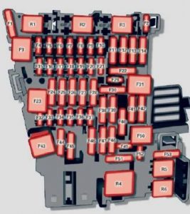
Instrument panel

Audi TTS Coupe - fuse box diagram - instrument panel
Audi TTS Coupe – fuse box diagram – instrument panel
Number Equipment
F1 Power top control modu le (Roadster)
F2 Power top control modu le (Roadster)
F3 ESC control module
F4 Central computer processor (MIB-2)
F5 Gateway
F6 Anti-theft alarm system
F7 Climate control system, selector lever (automatic transmission), parking heater, rear window heater relay coil
F8 Diagnosis, electrical parking brake switch, light switch, rain/light sensor, interior lighting
F9 Steering column switch module
F10 Display
F11 Haldex clutch
F12 MMI area
F13 Adaptive dampers control module
F14 Climate control system blower
F15 Electronic steering column lock
F16 MMI components, safety belt microphone (Roadster)
F17 Instrument cluster
F18 Rearview camera
F19 Convenience key system control module
F20 Power lumbar support adjustment
F22 Front passenger’s side upper cabin heating (Roadster)
F23 Right exterior lighting, on-board computer (right)
F25 Driver’s side door (for example power windows)
F26 Seat heating
F28 AMI High media port
F29 On-board computer
F31 Left on-board computer
F32 Driver assistance systems
F33 Airbag
F34 Socket relay, interior sound, back-up light switch, temperature sensor, oil level sensor
F35 Diagnosis, headlight range control system, air quality sensor, automatic dimming rearview mirror
F36 Right cornering light/ right LED-headlight
F37 Left cornering light/ left LED-headlight
F38 Engine control module, ESC control module
F39 Front passenger’s side door (for example power windows)
F40 Cigarette lighter, sockets
F41 SCR relay and delivery unit
F42 Central locking area
F43 On-board computer
F45 Power adjustable driver’s side seat
F46 Driver’s side upper cabin heating (Roadster)
F49 Starter, clutch sensor
F50 ESC valves
F53 Rear window defogger


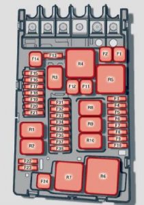
Engine compartment

Audi TTS Coupe - fuse box diagram - engine compartment
Audi TTS Coupe – fuse box diagram – engine compartment
Number Equipment
F1 ESC control module
F2 ESC control module
F3 Engine control module
F4 Engine cooling, engine components, auxiliary heater coil relay (1+2), secondary air injection pump relay
F5 Engine components, tank system
F6 Brake light sensor
F7 Engine components
F8 Oxygen sensor
F9 Engine components, exhaust door, glow time control module
F10 Fuel injectors, fuel control module
F11 Auxiliary heater heating element 2
F12 Auxiliary heater heating element 3
F13 Automatic transmission cont rol module
F15 Horn
F16 Ignition coil
F17 ESC control module , engine control module
F18 Terminal 30 (reference voltage)
F19 Windshield wipers
F20 Horn
F22 Terminal SO diagnos is
F23 Starter
F24 Auxiliary heater heating element 1
F32 LED headlights


WARNING: Terminal and harness assignments for individual connectors will vary depending on vehicle equipment level, model, and market.

Audi TTS Coupe (2014) – fuse box diagram

Audi TTS Coupe (2014) – fuse box diagram

Year of production: 2014

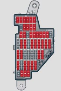
Instrument panel

Audi TTS Coupe - fuse box diagram - instrument panel
Audi TTS Coupe – fuse box diagram – instrument panel
Number Equipment Ampere rating [A]
1 Engine relay, fuel tank control unit, Airbag Off light, light switch (switch illumination), diagnostic connector 10
2 ABS, ASR, ESP, brake light switch 5
3 AFS headlight (left) 5
4 Oil level sensor (extended maintenance interval) (WIV), tire pressure monitoring system, switch for Electronic Stability Program (ESP), AFS headlights (control unit), A/C system (pressure sensor), backup light switch 5
5 Automatic headlight range control, AFS headlight (right)/ manual headlight range control, halogen headlights 5
10
6 Control unit for CAN data transfer (gateway), electromechanical steering, automatic transmission shift gate 5
7 Acoustic Park Assist, automatic dipping interior rear view mirror, garage door opener, heatable windshield washer nozzles, washer pump, wind deflector relay (Roadster) 5
8 Haldex clutch/Ha ldex clutch (TTS) 5
10
9 Control unit Audi magnetic ride 5
10 Airbag control unit 5
11 Mass airflow sensor, crankcase heating 5
10
12 Door control unit (central locking driver/passenger) 10
13 Diagnostic connector 10
14 Rain sensor, automatic transmission shift gate 5
15 Roof light (interior lighting) 5
16 A/C system (control unit) 10
17 Tire pressure monitoring system (control unit) 5
18
19
20
21 Fuel injectors (gasoline engine) 10
22 Wind deflector (Roadster) 30
23 Horn 20
24 Transmission (control unit) 15
25 Heater rear window Coupe/heated rear window Roadster 30
20
26 Driver’s side power window 30
27 Passenger’s side power window 30
28
29 Washer pump 15
30 Cigarette lighter 20
31 Starter 40
32 Steering column module 5
33 Instrument cluster 5
34 Radio navigation system, radio 20
15
35 Audio amplifier 30
36 Engine (control unit) 10
37 CAN (Gateway) 5
38 Cigarette lighter 20
39
40
41
42
43
44
45
46
47 SDARS tuner, cell phone package, TV tuner 5
48 VDA interface 5
49


Engine compartment

Number Equipment Ampere rating [A]
Fuse holder (black)
1
2
3
4
5 Anti-theft warning system (sensor), anti-theft warning system (horn) 5
6 Headlamp washer system 30
7 Electric fuel pumps (supply) 15
8 Windshield wipers 30
9 Heated seats (driver and passenger) 25
10 Lumbar support (driver and passenger ) 10
11
12 Ventilation blower 40
Fuse holder (brown )
1
2
3
4
5 Relay coil relay volume control valve 5
6 02 sensors 10
7 Positioning valves pre-wired engine harness 10
8 Ignition coils 20
9 Engine (control unit) 25
10 Water pump delayed-off 10
11 Feed (brake pedal) 5
12 Activated charcoal filter/charge pressure control valve 10


WARNING: Terminal and harness assignments for individual connectors will vary depending on vehicle equipment level, model, and market.