Dodge Ram Cargo Van (2012 – 2015) – fuse box diagram
Year of production: 2012, 2013, 2014, 2015
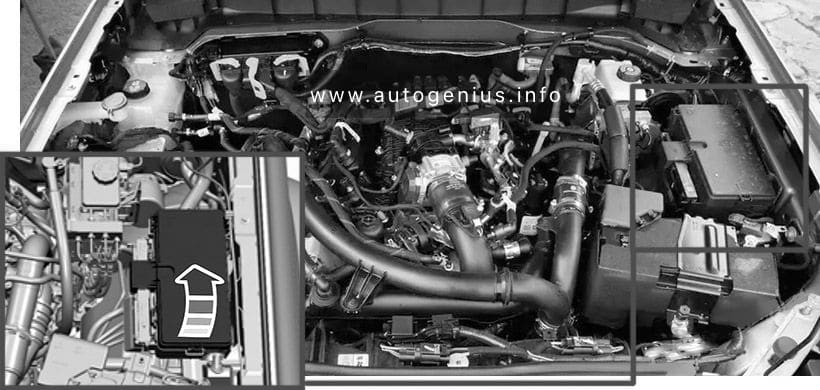
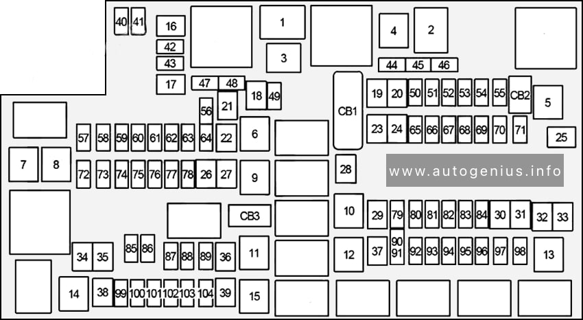
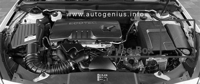
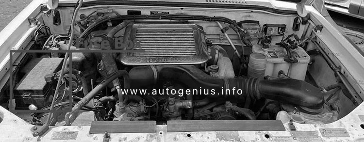
Engine Compartment – Totally Integrated Power Module
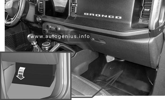
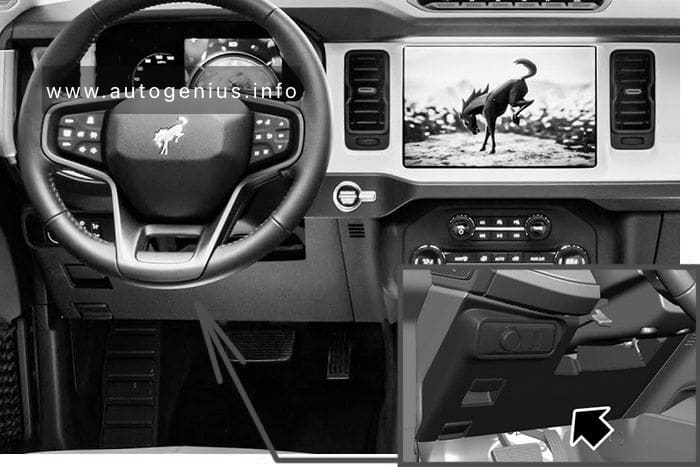
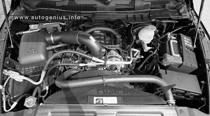
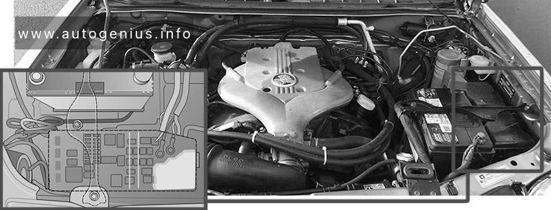
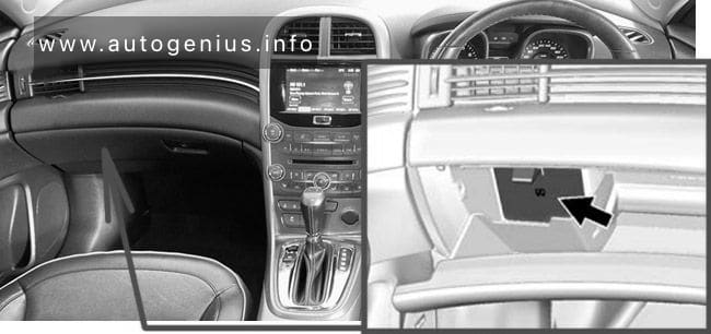
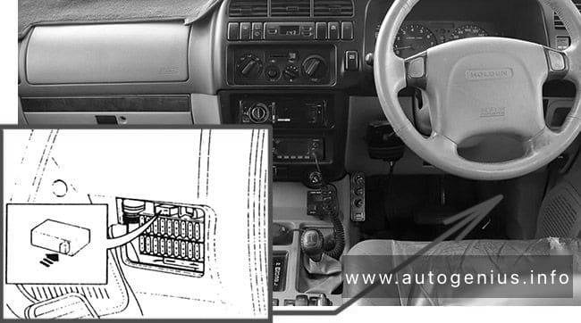
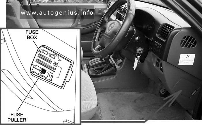
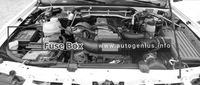
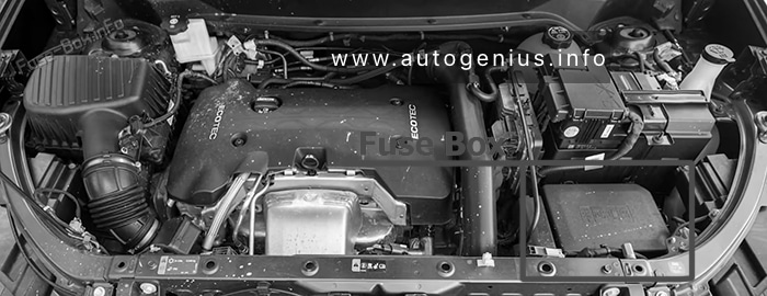
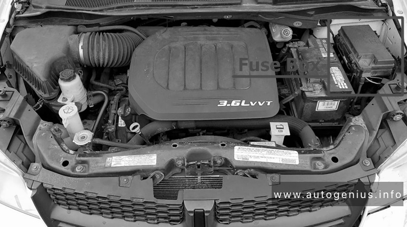
Fuse Box Location
The Totally Integrated Power Module is located in the engine compartment near the battery. This center contains cartridge fuses and mini-fuses. A label that identifies each component may be printed or embossed on the inside of the cover.
Power windows:
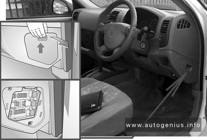
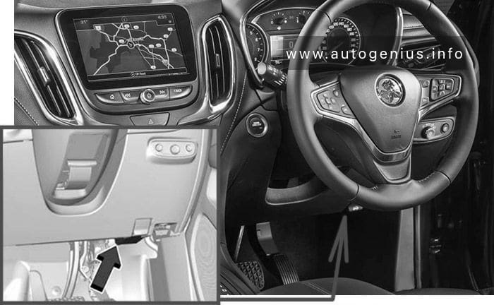
- 2012: The power windows are fused by a 25 Amp circuit breaker located under the instrument panel near the steering column.
- 2013-2015: The power windows are fused by a 25 Amp circuit breaker located in the Totally Integrated Power Module.
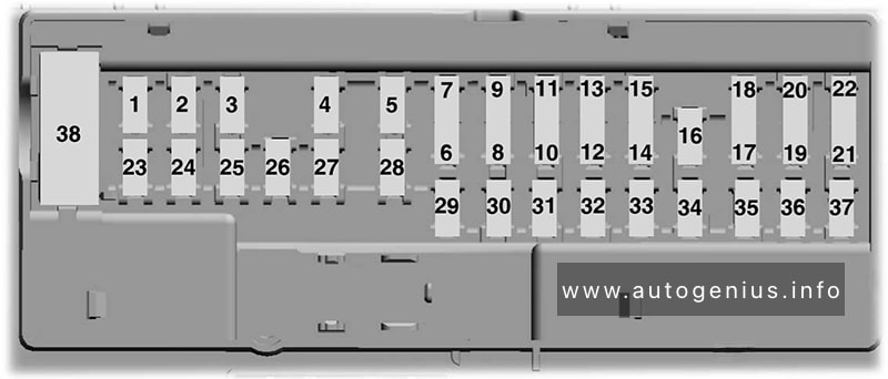
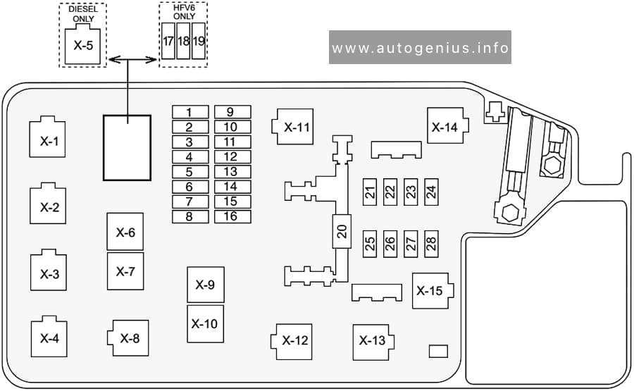
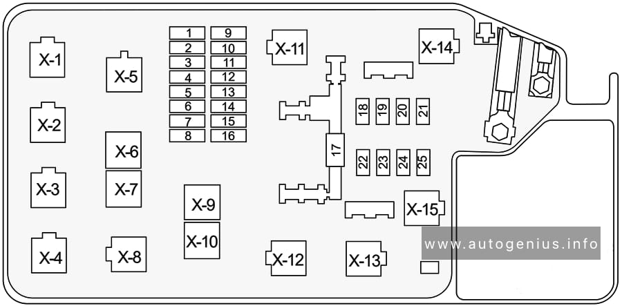
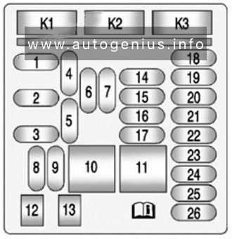
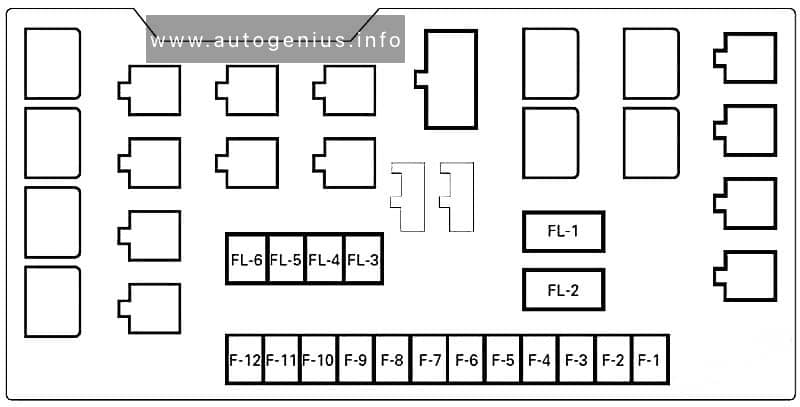
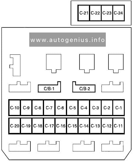
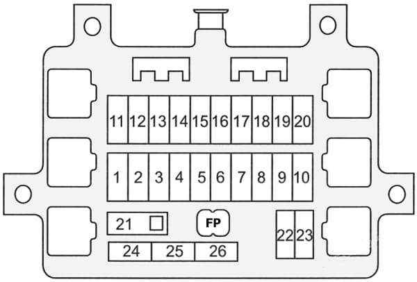
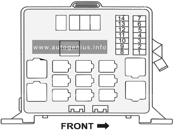
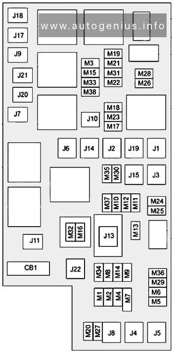
Fuse box diagram
| № | Cartridge Fuse | Mini-Fuse | Description |
|---|---|---|---|
| J1 | 40A Green | – | Power Folding Seat |
| J2 | 30A Pink | – | Power Liftgate Module |
| J3 | 30A Pink | – | Rear Door Module |
| J4 | 25A Clear | – | Driver Door Node |
| J5 | 25A Clear | – | Passenger Door Node |
| J6 | 40A Green | – | Antilock Brakes Pump / Stability Control System |
| J7 | 30A Pink | – | Antilock Brakes Valve / Stability Control System |
| J8 | 40A Green | – | Power Memory Seat – If Equipped |
| J9 | 40A Green | – | Partial Zero Emissions Vehicle Motor / Flex Fuel – If Equipped |
| J10 | 30A Pink | – | Headlamp Wash / Manifold Tuning Valve – If Equipped |
| J11 | 30A Pink | – | Power Sliding Door Module / Anti-Theft Module – If Equipped |
| J12 | 30A Pink | – | HVAC Rear Blower, Radiator Fan Motor |
| J13 | 60A Yellow | – | Ignition Off Draw (IOD) – Main |
| J14 | 40A Green | – | Rear Window Defogger |
| J15 | 40A Green | – | Front Blower |
| J17 | 40A Green | – | Starter Solenoid |
| J18 | 20A Blue | – | Powertrain Control Module Trans Range |
| J19 | 60A Yellow | – | Radiator Fan |
| J20 | 30A Pink | – | Front Wiper LO/HI |
| J21 | 20A Blue | – | Front/Rear Washer |
| J22 | 25A Clear | – | Sunroof Module |
| M1 | – | 15A Blue | Rear Center Brake Lamp / Brake Switch |
| M2 | – | 20A Yellow | 2012: Trailer Lighting, Front Fog Lamps, Intelligent Battery Sensor (IBS) 2013-2015: Front Fog Lamps |
| M3 | – | 20A Yellow | Front/Rear Axle Locker, Vacuum Pump Motor |
| M4 | – | 10A Red | Trailer Tow |
| M5 | – | 25A Clear | Inverter |
| M6 | – | 20A Yellow | Power Outlet #1 (ACC), Rain Sensor, Cigar Lighter (Instrument Panel or with Console Rear) |
| M7 | – | 20A Yellow | Power Outlet #2 (BATT/ACC SELECT) – Center Seat or with Console Rear |
| M8 | – | 20A Yellow | Front Heated Seat – If Equipped |
| M9 | – | 20A Yellow | Rear Heated Seat – If Equipped |
| M10 | – | 15A Blue | Ignition Off Draw – Video System, Satellite Radio, DVD, Hands-Free Module, Universal Garage Door Opener, Vanity Lamp, Streaming Video Module – If Equipped |
| M11 | – | 10A Red | Climate Control System |
| M12 | – | 30A Green | Amplifier / Radio |
| M13 | – | 20A Yellow | Instrument Cluster, SIREN, Clock Module, Multi-Function Control Switch – If Equipped |
| M14 | – | 20A Yellow | Trailer Tow – If Equipped |
| M15 | – | 20A Yellow | Rear View Mirror, Instrument Cluster, Multi-Function Control Switch, Tire Pressure Monitor, Glow Plug Module – If Equipped |
| M16 | – | 10A Red | Airbag Module / Occupant Classification Module |
| M17 | – | 15A Blue | Left Tail/License/Park Lamp, Running Lamps |
| M18 | – | 15A Blue | Right Tail/Park/Run Lamp |
| M19 | – | 25A Clear | Powertrain |
| M20 | – | 15A Blue | Instrument Cluster Interior Light, Switch Bank, Steering Column Module, Switch Steering Wheel |
| M21 | – | 20A Yellow | Powertrain |
| M22 | – | 10A Red | Horn |
| M23 | – | 10A Red | Horn |
| M24 | – | 25A Clear | Rear Wiper |
| M25 | – | 20A Yellow | Fuel Pump, Diesel Lift Pump – If Equipped |
| M26 | – | 10A Red | Power Mirror Switch, Driver Window Switch |
| M27 | – | 10A Red | Wireless Control Module, Keyless Entry Module |
| M28 | – | 10A Red | Powertrain, Transmission Control Module |
| M29 | – | 10A Red | Occupant Classification Module |
| M30 | – | 15A Blue | Rear Wiper Module, Power Folding Mirror |
| M31 | – | 20A Yellow | Back-Up Lamps |
| M32 | – | 10A Red | Airbag Module, THATCHUM – If Equipped |
| M33 | – | 10A Red | Powertrain |
| M34 | – | 10A Red | Park Assist, Heater Climate Control Module, Headlamp Wash, Compass, Rear Camera, Door Lamps, Flashlight, Relay Diesel Cabin Heater, Rad Fan Diesel – If Equipped |
| M35 | – | 10A Red | Heated Mirrors |
| M36 | – | 20A Yellow | Power Outlet #3 (Instrument Panel or with Console Center) |
| M37 | – | 10A Red | Antilock Brakes, Stability Control, Stop Lamp, Fuel Pump |
| M38 | – | 25A Clear | Door Lock/Unlock Motors, Liftgate Lock/Unlock Motors |
| CB1 | 25A circuit breaker | – | 2013-2015: Power Windows |
WARNING: Terminal and harness assignments for individual connectors will vary depending on vehicle equipment level, model, and market.