KIA Magentis (2006) – fuse box diagram

KIA Magentis (2006) – fuse box diagram

Also called:

  • Kia Optima
  • Kia Lotze

Year of production: 2006

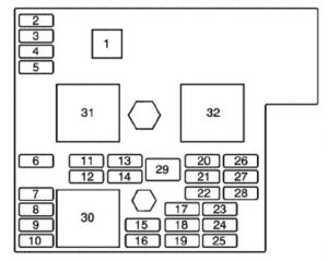
Instrument panel (Driver’s side kick panel)

KIA Magentis - fuse box diagram - driver's side kick panel
KIA Magentis – fuse box diagram – driver’s side kick panel
Description Fuse rating Protected component
RR HTD IND 10 Rear window defroster, Outside rear view mirror heater
HAZARD 10 Hazard light, Turn signal lights
RR FOG 15 Rear fog light
A/CON 10 Air conditioning system
ETACS 10 ETACS, Keyless entry system, Door lock system
DR LOCK 15 Power door lock
P/SEAT (DRIVE) 25 Power seat
T/LID OPEN 15 Remote trunk lid
STOP LP 15 Stop lights
H/LP 10 Head light
A/BAG IND 10 Air-bag
T/SIG 10 Turn signal lights
A/CON SW 10 Air conditioning system
ACC SOCKET 15 Power outlet
S/HTR 15 Seat heater
A/BAG 15 Air-bag
B/UP 10 Backup lights
CLUSTER 10 Cluster
START 10 Engine switch
SP1 15 Spare fuse
FRT HTD 15 Window defroster
P/SEAT (PASS) 25 Power Seat
SP4 15 Spare fuse
D/CLOCK 10 Digtal clock
TAIL(LH) 10 Position lights, License plate lights, Tail lights
AUDIO 10 Audio
WIPER 20 Wiper
ROOM LP 10 Dome lights, Front door edge warning lights
TAIL(RH) 10 Position lights, License plate lights, Tail lights
C/LIGHTER 15 Cigar lighter
EPS 10


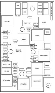
Engine compartment

KIA Magentis - fuse box diagram - engine compartment
KIA Magentis – fuse box diagram – engine compartment
Description Fuse rating Protected component Fuse number
COND FAN 20 Condenser fan
PWR WIND 40 Power window
ABS 2 20 ABS
IGN SW-1 30 Ignition switch
ABS 1 40 ABS
IGN SW-2 30 Ignition switch
RAD FAN MTR 30 Radiator fan motor
FUEL PUMP 20 Fuel pump 1
HD LP LO 15 Headlights (LO) 2
ABS 10 ABS 3
INJECTOR 10 Injector 4
A/C COMPR 10 Air-con compressor 5
ATM RLY 20 ATM Relay 6
ECU RLY 30 Engine control unit relay 7
IG COIL 20 Ignition coil 8
O2 SNSR 15 Oxygen sensor 9
ECU 15 Engine control unit 10
HORN 10 Horn 11
HEAD LP HI 15 Headlights (HI) 12
HEAD LP WASH 20 13
DRL 15 DRL 14
FR FOG 15 Front fog lights 15
DIODE-1 Diode 1 16
SPARE 30 Spare fuse 17
SPARE 20 Spare fuse 18
SPARE 15 Spare fuse 19
SPARE 10 Spare fuse 20
DIODE-2 Diode 2 21
BLOWER 30 Blower 22
PWR FUSE-2 30 Power fuse 2 23
PWR AMP 20 Power amp 24
SUNROOF 15 Sunroof 25
TAIL LP 20 Tail lights 26
PWR FUSE-1 30 Power fuse 1 27
ECU 10 ECU 28
RR HTD 30 Rear window defroster 29

WARNING: Terminal and harness assignments for individual connectors will vary depending on vehicle equipment level, model, and market

KIA Sportage (QL; 2017 – 2023) – fuse box diagram

KIA Sportage (QL; 2017 – 2023) – fuse box diagram

Year of production: 2017, 2018, 2019, 2020, 2021, 2022


The 4th generation Kia Sportage was produced in 2016, 2017, 2018, 2019, 2020, 2021, 2022, 2023 with both gasoline and diesel engines. In this publication you will find a designation of the 4th generation Kia Sportage fuses and relays with boxes diagrams and their locations. Let’s highlight the fuse responsible for the cigarette lighter.

Instrument panel (driver’s side fuse panel)

Fuse box location

Located under the dashboard on the driver’s side behind the protective cover.

KIA Sportage (QL; 2017 - 2023) - fuse box location - passenger compartment
KIA Sportage (QL; 2017 – 2023) – fuse box location – passenger compartment


Fuse box diagram

Version 1
KIA Sportage (QL; 2017 - 2023) - fuse box diagram - passenger compartment (version 1)
KIA Sportage (QL; 2017 – 2023) – fuse box diagram – passenger compartment (version 1)


Version 2
KIA Sportage (QL; 2017 - 2023) - fuse box diagram - passenger compartment (version 2)
KIA Sportage (QL; 2017 – 2023) – fuse box diagram – passenger compartment (version 2)


Fuse name Ampere rating [A] Protected component
MDPS 7,5 MDPS Unit
MODULE 2 10 Headlamp LH/RH
SMART KEY 1 10 Smart Key Control Module/Immobilizer Module
A/BAG IND 7,5 Instrument Cluster
[Audio & Manual A/C] Hazard Switch
[Audio & Auto A/C] A/C Control Module
[Navigation] Center Facia Lamp
MODULE 4 10 Console Switch, Blind Spot Detection Radar LH/RH, AWD ECM, Crash Pad Switch, BCM, Lane Departure Warning Control Module
A/BAG 15 SRS Control Module
START 7,5 [W/O Smart Key & IMMO.] ICM Relay Box (Burglar Alarm Relay), Ignition Switch
[With Smart Key / IMMO.] Transaxle Range Switch, ECM, Smart Key Control Module
MODULE 3 10 Front/Rear Seat Warmer Control Module, ATM Shift Lever ILL., Front Air Ventilation Seat Control Module, A/V & Navigation Head Unit, Electro Chromic Mirror, Audio, A/C Control Module, Multipurpose Check Connector, Adaptive Front Lighting Module
CLUSTER 10 Instrument Cluster
MODULE 9 20 PCB Block (Fuse – ABS 3, VACUUM PUMP 2, ECU 6, AEB, TCU 2, MODULE)
HEATED
STEERING
15 BCM
MODULE 6 7,5 Front/Rear Seat Warmer Control Module, Front Air Ventilation Seat Control Module
MODULE 5 10 BCM, Smart Key Control Module
A/CON 2 7,5 A/C Control Module
MODULE 1 10 BCM, ATM Shift Lever
P/ WINDOW LH 25 Power Window Main Switch
A/CON 1 7,5 A/C Control Module, Cluster Ionizer, E/R Junction Block (Blower Relay)
WIPER RR 15 Rear Wiper Motor, ICM Relay Box (Rear Wiper Relay)
WASHER 15 Multifunction Switch
SMART KEY 3 10 [W/O Smart Key] Immobilizer Module
[With Smart Key] Smart Key Control Module, Start/Stop Button Switch
STOP LAMP 7,5 Smart Key Control Module, Stop Lamp Switch
P/ WINDOW RH 25 Power Window Main Switch, Passenger Power Window Switch
MEMORY 10 Wireless Charger, Instrument Cluster, Data Link Connector, BCM, ICM Relay Box (Outside Mirror
Folding/Unfolding Relay), Electro Chromic Mirror, A/C Control Module, Console Switch
SUN ROOF 1 20 Panorama Sunroof
TAIL GATE
OPEN
10 Tail Gate Relay
INTERIOR LAMP 10 Ignition Key Ill.& Door Warning Switch, Room Lamp, Overhead Console Lamp, Front Vanity Lamp LH/RH, Rear Personal Lamp LH/RH, Luggage Lamp, Glove Box Lamp
SMART KEY 2 15 Smart Key Control Module
MODULE 8 7,5 Key Solenoid
MULTI MEDIA 15 Audio, A/V & Navigation Head Unit, Rear USB Charger
S/HEATER
DRV/PASS
20 Front Seat Warmer Control Module, Front Air Ventilation Seat Control Module
SUN ROOF 2 20 Panorama Sunroof
P/SEAT (PASS) 30 Passenger Seat Manual Switch
POWER OUTLET 20 Front Power Outlet #1 (Front Cigarette Lighter)
S/HEATER
REAR
20 Rear Seat Warmer Control Module
DOOR LOCK 20 Door Lock/Unlock Relay
4WD 20 AWD ECM
MODULE 7 10 Hazard Switch, Driver/Passenger Smart Key Outside Handle, AEB Sensor
AMP 25 AMP
SAFETY
P/ WINDOW
25 Driver Safety Power Window Module
HEATED
MIRROR
10 Driver/Passenger Power Outside Mirror, A/C Control Module
P/SEAT (DRV) 30 Driver Seat Manual Switch
ACC 10 Rear USB Charger, AMP, Power Outside Mirror Switch, PCB Block(Power Outlet Relay), Smart Key Control Module, Audio, A/V & Navigation Head Unit, BCM, Wireless Charger

Engine compartment fuse panel

Fuse box location

Located on the left side of the engine compartment.

KIA Sportage (QL; 2017 - 2023) - fuse box location - engine compartment
KIA Sportage (QL; 2017 – 2023) – fuse box location – engine compartment


Fuse box diagram

Version 1
KIA Sportage (QL; 2017 - 2023) - fuse box diagram - engine compartment (version 1)
KIA Sportage (QL; 2017 – 2023) – fuse box diagram – engine compartment (version 1)


Version 2
KIA Sportage (QL; 2017 - 2023) - fuse box diagram - engine compartment (version 2)
KIA Sportage (QL; 2017 – 2023) – fuse box diagram – engine compartment (version 2)


Fuse name Ampere rating [A] Protected component
MULTI FUSE COOLING FAN 2 80 Cooling Fan Motor
MDPS 80 MDPS Unit
B+ 1 60 Smart Junction Block (IPS 2 (5CH), IPS 3 (2CH), IPS 4 (2CH), IPS 5 (2CH), IPS 6 (1CH), Fuse – AMP)
B+ 2 60 Smart Junction Block (IPS 1 (5CH), Fuse – MODULE 7, SMART KEY 2, SMART KET 3, MODULE 8, STOP LAMP)
B+ 3 50 Smart Junction Block (Fuse – SUNROOF 1, SUNROOF 2, S/HEATER DRV/PASS, S/HEATER REAR, SAFETY P/WINDOW, Power Window Relay
BLOWER 40 Blower Relay
REAR HEATED 40 Rear Heated Relay
IG1 40 [W/O Smart Key] Ignition Switch, [With Smart Key] PCB Block (PDM (IG1)/PDM (ACC) Relay)
IG2 30 Start Relay, [W/O Smart Key] Ignition Switch, [With Smart Key] PCB Block (PDM (IG2) Relay)
FUSE B+ 4 50 Smart Junction Block (Fuse – AWD, P/SEAT (DRV), P/SEAT (PASS), TAIL GATE OPEN, DOOR LOCK, Leak Current Autocut Device Relay)
COOLING FAN 1 50 Cooling Fan 1 Relay
ABS 1 40 ESC Control Module, Multipurpose Check Connector
POWER
TAIL GATE
40 Power Tail Gate Module
ABS 2 40 ESC Module
COOLING FAN 3 40 Cooling Fan 1 Relay
E-CVVT 1 20 PCM
E-CVVT 2 20 PCM
WIPER FRT 1 30 [W/O Smart Key] Ignition Switch, [With Smart Key] PDM (IG2) Relay
TCU 1 15 PCM
WIPER FRT 2 10 BCM, PCM
ECU 3 20 PCM
HORN 15 A Horn Relay
BATTERY
MANAGEMENT
10 Battery Sensor
SENSOR 2 10 Fuel Pump Relay, Oil Control Valve, Purge Control Solenoid Valve, Variable Intake Solenoid Valve, RCV Control Solenoid Valve
SENSOR 1 15 Oxygen Sensor (Up/Down)
ECU 2 20 Ignition Coil #1/#2/#3/#4
ECU 4 15 PCM
SENSOR 3 10 E/R Junction Block (Cooling Fan 1 Relay), Canister Close Valve
FUEL PUMP 20 Fuel Pump Relay
AEB 10 AEB Sensor
MODULE 7,5 Stop Lamp Switch
B/ALARM
HORN
10 E/R Junction Block (B/Alarm Horn Relay)
H/LAMP HI 10 BI-Function H/LP Relay
ABS 3 10 ESC Module
POWER
OUTLET 1
20 Front Power Outlet #2
ECU 6 10 PCM
TCU 2 15 Transaxle Range Switch
B/UP LAMP 10 Rear Bumper Lamp LH/RH, Electro Chromic Mirror
POWER
OUTLET 2
20 Rear Power Outlet
ECU 1 30 Engine Control Relay
DEICER 15 E/R Junction Block (Deicer Relay)
VACUUM
PUMP 1
20 Vacuum Pump
VACUUM
PUMP 2
15 Vacuum Pump, Cooling Fan Motor, Vacuum Switch


Relay

Relay name Type
Cooling Fan 1 Relay MINI
Rear Defogger Relay MICRO
B/A Horn Relay MICRO
Deicer Relay MICRO
Cooling Fan 2 Relay MICRO
Start Relay MICRO
Blower Relay MICRO


Engine compartment fuse panel (Battery terminal cover)

On the positive terminal of the storage battery there is a high-power main power fuse made in the form of a fusible link.

KIA Sportage (QL; 2017 - 2023) - fuse box diagram - engine compartment (battery terminal cover)
KIA Sportage (QL; 2017 – 2023) – fuse box diagram – engine compartment (battery terminal cover)

WARNING: Terminal and harness assignments for individual connectors will vary depending on vehicle equipment level, model, and market.

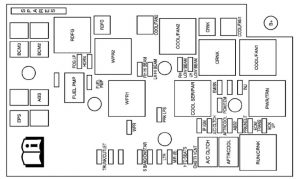
KIA Sportage (2014 – 2016) – fuse box diagram

KIA Sportage (2014 -2016) – fuse box diagram

Year of production: 2014, 2015, 2016

Instrument panel

KIA Sportage - fuse box diagram - instrument panel
KIA Sportage – fuse box diagram – instrument panel
Fuse name Ampere rating [A] Protected component
POWER CONNECTOR AUDIO – 20 Audio
RF_ANT – 7,5 RF Receiver
A/BAG 15 SRS Control Module, Passenger Occupant Detection Sensor, Telltale & SBR Lamp
S/HEATER FRT 15 Driver/Passenger Seat Warmer Switch
S/HEATER RR 15 Rear Seat Warmer LH/RH
A/CON 7,5 A/C Control Module (Auto)
HTD MIRR 7,5 A/C Control Module, Driver/Passenger Power Outside Mirror
CLUSTER 10 Driver/Passenger Seat Warmer Switch, Driver CCS Control Module, Instrument Cluster, Tire Pressure Monitoring Module, Audio, Alternator, BCM, A/C Control Module, Telltale & SBR Lamp
IG2 A 10 BCM, Smart Key Control Module, IPS Control Module (IG2)
WIPER RR 15 Rear Wiper Motor, Multifunction Switch (Wiper), ICM Relay Box (Rear Wiper Relay)
IG2 B 10 Cluster Ionizer, A/C Control Module, Rain Sensor, Sunroof Motor, Electro Chromic Mirror, E/R Fuse & Relay Box (Blower Relay)
POWER OUTLET 2 20 Rear Power Outlet, Front Power Outlet LH, Front Cigarette Lighter
A/BAG IND 10 Instrument Cluster (A/Bag IND.)
SMART KEY 2 10 Smart Key Control Module
WIPER FRT 25 Front Wiper Motor, Multifunction Switch (Wiper), E/R Fuse & Relay Box (Front Wiper (Low) Relay, Wiper (Rain Sensor) Relay)
POWER OUTLET 1 15 Front Power Outlet RH
SMART KEY 1 10 BCM, Smart Key Control Module
ACC 10 Audio, Amp, Sunroof Control Module, Power Outside Mirror Switch
START 10 Burglar Alarm Relay (With Burglar Alarm), E/R Fuse & Relay Box (Start Relay : W/O Burglar Alarm & Smart Key), Smart Key Control Module (W/O Burglar Alarm & With Smart Key)
MODULE IG1 10 EPS Control Module, ATM Shift Lever ILL., 4WD ECM, Stop Lamp Switch, IPS Control Module (IG1)
UH_BOX 20 E/R Fuse & Relay Box (ECU 2 7.5A, ABS 7.5A, TCU 2 7.5A)
ROOM LP 10 BCM, Map Lamp, Room Lamp, Driver/Passenger Vanity Lamp, Electro Chromic Mirror, Luggage Lamp, Ignition Key ILL. & Door Warning Switch, Tire Pressure Monitoring Module, Instrument Cluster (MCU, IND.), A/C Control Module, IPS Control Module (B+)
PDM B 10 Start/Stop Button Switch, FOB Holder, Smart Key Control Module
DR LOCK 15 Door Lock Relay, Door Unlock Relay, Tail Gate Relay, ICM Relay Box (Two Turn Unlock Relay)
HAZARD 15 BCM
FOG LP RR 10
PDM A 25 Smart Key Control Module
ATM K/LOCK 7,5 ATM Shift Lever, Key Solenoid
CORNERING LAMP 10
SEAT VENT 15 Driver CCS Seat Warmer
P/WDW RH 25 Power Window Main Switch, Passenger Power Window Switch, Rear Power Window Switch RH
P/WDW LH 25 Rear Power Window Switch LH, Power Window Main Switch
SAFETY POWER
WINDOW
20 Driver Safety Power Window Module
P/SEAT(DRV) 20 Driver Seat Manual Switch
MODULE B+ 10 Multipurpose Check Connector, Data Link Connector, Driver CCS Switch, Rear Parking Assist Buzzer
SUNROOF 15 Sunroof Motor, Sunroof Control Module
AMP 25 Amp
HTD_STRG 15 Heated steering wheel

Engine compartment fuse panel

KIA Sportage - fuse box diagram - engine compartment
KIA Sportage – fuse box diagram – engine compartment
KIA Sportage - fuse box diagram - engine compartment
KIA Sportage – fuse box diagram – engine compartment
Fuse name Ampere rating [A] Protected component
MULTI FUSE MDPS 80 EPS Control Module
B+1 60 I/P Junction Box (PDM A 25A, DR LOCK 15A, HAZARD 15A, IPS 4~7)
ABS 2 40 ESC Module
EMS 40 EMS Box (TCU 1 15A, ECU 30A, A/CON 10A, F/PUMP 15A)
ABS 1 40 ESC Module
BLOWER 40 Blower Relay
B+3 60 I/P Junction Box (P/SEAT(DRV) 20A, SAFETY POWER WINDOW 20A, PDM B 10A, ATM K/LOCK 7.5A, SEAT VENT 15A, Power Connector (AUDIO 20A, RF_ANT 7.5A), ROOM LP 10A)
B+2 60 I/P Junction Box (Power Window Relay, SUNROOF 15A, AMP 25A, MODULE B+ 10A, IPS 0~3, IPS 8~10)
FUSE C/FAN (MPI engine) 40 Cooling Fan (High) Relay, Cooling Fan (Low) Relay
C/FAN (T-GDI engine) 50 Cooling Fan (High) Relay, Cooling Fan (Low) Relay
RR HTD 40 Rear Defogger Relay
IG 1 30 PDM Relay Box (IGN1/ACC Relay : With Smart Key), Ignition Switch (W/O Smart Key)
IG 2 40 PDM Relay Box (IGN2 Relay : With Smart Key), Ignition Switch (W/O Smart Key)
HORN 15 Horn Relay
DEICER 15 Front Wiper Deicer Relay
STOP LP 10 Stop Lamp Switch, Smart Key Control Module, ICM Relay Box (DBC Relay)
4WD 20 4WD ECM
AMS 10 Battery Sensor
TCU 2 (MPI engine) 7,5 Transaxle Range Switch
TCU 2 (T-GDI engine) 7,5 Transaxle Range Switch, Vacuum Switch, Vacuum Pump Relay
ABS 7,5 ESC Module, ICM Relay Box (DBC Relay), Multi Switch
ECU 2 7,5 ATM P/N Relay, PCM, Multifunction Switch (Remote Control)
V_PUMP (T-GDI engine) 20 Vacuum Pump Relay


Engine compartment main fuse panel (EMS Box)

Fuse name Ampere rating [A] Protected component
F/PUMP 15 Fuel Pump Relay
SENSOR 4 15 Fuel Pump Relay, PCM, Oxygen Sensor (Up)/(Down),
E/R Fuse & Relay Box (Cooling Fan (High)/(Low) Relay)
SENSOR 3 10 A/CON Relay, Injector #1~#4
SENSOR 2 10
TCU 1 15 PCM
A/CON 10 A/CON Relay
SENSOR 1 (MPI engine) 10 Immobilizer Module, Crankshaft Position Sensor, Camshaft Position Sensor #1/#2, Oil Control Valve #1/#2Canister Purge Control Solenoid Valve, Variable Intake Solenoid Valve, Canister Close Valve
SENSOR 1 (T-GDI engine) 10 Immobilizer Module, Crankshaft Position Sensor, Camshaft Position Sensor #1/#2, Oil Control Valve #1/#2Canister Purge Control Solenoid Valve, Variable Intake Solenoid Valve, Canister Close Valve, RCV
ECU 1 20 Ignition Coil #1~#4, Condenser
ECU 30 Engine Control Relay

WARNING: Terminal and harness assignments for individual connectors will vary depending on vehicle equipment level, model, and market.
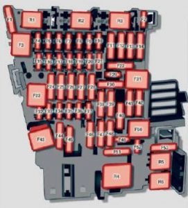
KIA Sportage (2012 – 2013) – fuse box diagram

KIA Sportage (2012 – 2013) – fuse box diagram

Year of production: 2012, 2013

Inner fuse panel

Fuse name Ampere rating [A] Protected component
POWER CONNECTOR AUDIO – 20 Audio
RF_ANT – 7,5 RF Receiver
A/BAG 15 SRS Control Module, Passenger Occupant Detection Sensor, Telltale & SBR Lamp
S/HEATER FRT 15 Driver/Passenger Seat Warmer Switch
S/HEATER RR 15 Rear Seat Warmer LH/RH
A/CON 7,5 A/C Control Module (Auto)
HTD MIRR 7,5 A/C Control Module, Driver/Passenger Power Outside Mirror
CLUSTER 10 Driver/Passenger Seat Warmer Switch, Driver CCS Control Module, Instrument Cluster, Tire Pressure Monitoring Module, Audio, Alternator, BCM, A/C Control Module, Telltale & SBR Lamp
IG2 A 10 BCM, Smart Key Control Module, IPS Control Module (IG2)
WIPER RR 15 Rear Wiper Motor, Multifunction Switch (Wiper), ICM Relay Box (Rear Wiper Relay)
IG2 B 10 Cluster Ionizer, A/C Control Module, Rain Sensor, Sunroof Motor, Electro Chromic Mirror, E/R Fuse & Relay Box (Blower Relay)
POWER OUTLET 2 20 Rear Power Outlet, Front Power Outlet LH, Front Cigarette Lighter
A/BAG IND 10 Instrument Cluster (A/Bag IND.)
SMART KEY 2 10 Smart Key Control Module
WIPER FRT 25 Front Wiper Motor, Multifunction Switch (Wiper), E/R Fuse & Relay Box (Front Wiper (Low) Relay, Wiper (Rain Sensor) Relay)
POWER OUTLET 1 15 Front Power Outlet RH
SMART KEY 1 10 BCM, Smart Key Control Module
ACC 10 Audio, Amp, Sunroof Control Module, Power Outside Mirror Switch
START 10 Burglar Alarm Relay (With Burglar Alarm), E/R Fuse & Relay Box (Start Relay : W/O Burglar Alarm & Smart Key), Smart Key Control Module (W/O Burglar Alarm & With Smart Key)
MODULE IG1 10 EPS Control Module, ATM Shift Lever ILL., 4WD ECM, Stop Lamp Switch, IPS Control Module (IG1)
UH_BOX 20 E/R Fuse & Relay Box (ECU 2 7.5A, ABS 7.5A, TCU 2 7.5A)
ROOM LP 10 BCM, Map Lamp, Room Lamp, Driver/Passenger Vanity Lamp, Electro Chromic Mirror, Luggage Lamp, Ignition Key ILL. & Door Warning Switch, Tire Pressure Monitoring Module, Instrument Cluster (MCU, IND.), A/C Control Module, IPS Control Module (B+)
PDM B 10 Start/Stop Button Switch, FOB Holder, Smart Key Control Module
DR LOCK 15 Door Lock Relay, Door Unlock Relay, Tail Gate Relay, ICM Relay Box (Two Turn Unlock Relay)
HAZARD 15 BCM
FOG LP RR 10
PDM A 25 Smart Key Control Module
ATM K/LOCK 7,5 ATM Shift Lever, Key Solenoid
CORNERING LAMP 10
SEAT VENT 15 Driver CCS Seat Warmer
P/WDW RH 25 Power Window Main Switch, Passenger Power Window Switch, Rear Power Window Switch RH
P/WDW LH 25 Rear Power Window Switch LH, Power Window Main Switch
SAFETY POWER
WINDOW
20 Driver Safety Power Window Module
P/SEAT(DRV) 20 Driver Seat Manual Switch
MODULE B+ 10 Multipurpose Check Connector, Data Link Connector, Driver CCS Switch, Rear Parking Assist Buzzer
SUNROOF 15 Sunroof Motor, Sunroof Control Module
AMP 25 Amp
HTD_STRG 15 Heated steering wheel

Engine compartment fuse panel

Fuse name Ampere rating [A] Protected component
MULTI FUSE MDPS 80 EPS Control Module
B+1 60 I/P Junction Box (PDM A 25A, DR LOCK 15A, HAZARD 15A, IPS 4~7)
ABS 2 40 ESC Module
EMS 40 EMS Box (TCU 1 15A, ECU 30A, A/CON 10A, F/PUMP 15A)
ABS 1 40 ESC Module
BLOWER 40 Blower Relay
B+3 60 I/P Junction Box (P/SEAT(DRV) 20A, SAFETY POWER WINDOW 20A, PDM B 10A, ATM K/LOCK 7.5A, SEAT VENT 15A, Power Connector (AUDIO 20A, RF_ANT 7.5A), ROOM LP 10A)
B+2 60 I/P Junction Box (Power Window Relay, SUNROOF 15A, AMP 25A, MODULE B+ 10A, IPS 0~3, IPS 8~10)
FUSE C/FAN 40 Cooling Fan (High) Relay, Cooling Fan (Low) Relay
RR HTD 40 Rear Defogger Relay
IG 1 30 PDM Relay Box (IGN1/ACC Relay : With Smart Key), Ignition Switch (W/O Smart Key)
IG 2 40 PDM Relay Box (IGN2 Relay : With Smart Key), Ignition Switch (W/O Smart Key
HORN 15 Horn Relay
DEICER 15 Front Wiper Deicer Relay
STOP LP 10 Stop Lamp Switch, Smart Key Control Module, ICM Relay Box (DBC Relay)
4WD 20 4WD ECM
AMS 10 Battery Sensor
TCU 2 (MPI engine) 7,5 Transaxle Range Switch
TCU 2 (T-GDI engine) 7,5 Transaxle Range Switch, Vacuum Switch, Vacuum Pump Relay
ABS 7,5 ESC Module, ICM Relay Box (DBC Relay), Multi Switch
ECU 2 7,5 ATM P/N Relay, PCM, Multifunction Switch (Remote Control)
V_PUMP (T-GDI engine) 20 Vacuum Pump Relay


Engine compartment main fuse panel (EMS Box)

Fuse name Ampere rating [A] Protected component
F/PUMP 15 Fuel Pump Relay
SENSOR 4 15 Fuel Pump Relay, PCM, Oxygen Sensor (Up)/(Down),
E/R Fuse & Relay Box (Cooling Fan (High)/(Low) Relay)
SENSOR 3 10 A/CON Relay, Injector #1~#4
SENSOR 2 10
TCU 1 15 PCM
A/CON 10 A/CON Relay
SENSOR 1 (MPI engine) 10 Immobilizer Module, Crankshaft Position Sensor, Camshaft Position Sensor #1/#2, Oil Control Valve #1/#2Canister Purge Control Solenoid Valve, Variable Intake Solenoid Valve, Canister Close Valve
SENSOR 1 (T-GDI engine) 10 Immobilizer Module, Crankshaft Position Sensor, Camshaft Position Sensor #1/#2, Oil Control Valve #1/#2Canister Purge Control Solenoid Valve, Variable Intake Solenoid Valve, Canister Close Valve, RCV
ECU 1 20 Ignition Coil #1~#4, Condenser
ECU 30 Engine Control Relay

WARNING: Terminal and harness assignments for individual connectors will vary depending on vehicle equipment level, model, and market.
KIA Sportage (2011) – fuse box diagram

KIA Sportage (2011) – fuse box diagram

Year of production: 2011

Inner fuse panel

Fuse name Ampere rating [A] Protected component
POWER CONNECTOR AUDIO – 20 Audio
RF_ANT – 7,5 RF Receiver
A/BAG 15 SRS Control Module, Passenger Occupant Detection Sensor, Telltale & SBR Lamp
S/HEATER FRT 15 Driver/Passenger Seat Warmer Switch
S/HEATER RR 15 Rear Seat Warmer LH/RH
A/CON 7,5 A/C Control Module (Auto)
HTD MIRR 7,5 A/C Control Module, Driver/Passenger Power Outside Mirror
CLUSTER 10 Driver/Passenger Seat Warmer Switch, Driver CCS Control Module, Instrument Cluster, Tire Pressure Monitoring Module, Audio, Alternator, BCM, A/C Control Module, Telltale & SBR Lamp
IG2 A 10 BCM, Smart Key Control Module, IPS Control Module (IG2)
WIPER RR 15 Rear Wiper Motor, Multifunction Switch (Wiper), ICM Relay Box (Rear Wiper Relay)
IG2 B 10 Cluster Ionizer, A/C Control Module, Rain Sensor, Sunroof Motor, Electro Chromic Mirror, E/R Fuse & Relay Box (Blower Relay)
POWER OUTLET 2 20 Rear Power Outlet, Front Power Outlet LH, Front Cigarette Lighter
A/BAG IND 10 Instrument Cluster (A/Bag IND.)
SMART KEY 2 10 Smart Key Control Module
WIPER FRT 25 Front Wiper Motor, Multifunction Switch (Wiper), E/R Fuse & Relay Box (Front Wiper (Low) Relay, Wiper (Rain Sensor) Relay)
POWER OUTLET 1 15 Front Power Outlet RH
SMART KEY 1 10 BCM, Smart Key Control Module
ACC 10 Audio, Amp, Sunroof Control Module, Power Outside Mirror Switch
START 10 Burglar Alarm Relay (With Burglar Alarm), E/R Fuse & Relay Box (Start Relay : W/O Burglar Alarm & Smart Key), Smart Key Control Module (W/O Burglar Alarm & With Smart Key)
MODULE IG1 10 EPS Control Module, ATM Shift Lever ILL., 4WD ECM, Stop Lamp Switch, IPS Control Module (IG1)
UH_BOX 20 E/R Fuse & Relay Box (ECU 2 7.5A, ABS 7.5A, TCU 2 7.5A)
ROOM LP 10 BCM, Map Lamp, Room Lamp, Driver/Passenger Vanity Lamp, Electro Chromic Mirror, Luggage Lamp, Ignition Key ILL. & Door Warning Switch, Tire Pressure Monitoring Module, Instrument Cluster (MCU, IND.), A/C Control Module, IPS Control Module (B+)
PDM B 10 Start/Stop Button Switch, FOB Holder, Smart Key Control Module
DR LOCK 15 Door Lock Relay, Door Unlock Relay, Tail Gate Relay, ICM Relay Box (Two Turn Unlock Relay)
HAZARD 15 BCM
FOG LP RR 10
PDM A 25 Smart Key Control Module
ATM K/LOCK 7,5 ATM Shift Lever, Key Solenoid
CORNERING LAMP 10
SEAT VENT 15 Driver CCS Seat Warmer
P/WDW RH 25 Power Window Main Switch, Passenger Power Window Switch, Rear Power Window Switch RH
P/WDW LH 25 Rear Power Window Switch LH, Power Window Main Switch
SAFETY POWER
WINDOW
20 Driver Safety Power Window Module
P/SEAT(DRV) 20 Driver Seat Manual Switch
MODULE B+ 10 Multipurpose Check Connector, Data Link Connector, Driver CCS Switch, Rear Parking Assist Buzzer
SUNROOF 15 Sunroof Motor, Sunroof Control Module
AMP 25 Amp

Engine compartment fuse panel

Fuse name Ampere rating [A] Protected component
MULTI FUSE MDPS 80 EPS Control Module
B+1 60 I/P Junction Box (PDM A 25A, DR LOCK 15A, HAZARD 15A, IPS 4~7)
ABS 2 40 ESC Module
EMS 40 EMS Box (TCU 1 15A, ECU 30A, A/CON 10A, F/PUMP 15A)
ABS 1 40 ESC Module
BLOWER 40 Blower Relay
B+3 60 I/P Junction Box (P/SEAT(DRV) 20A, SAFETY POWER WINDOW 20A, PDM B 10A, ATM K/LOCK 7.5A, SEAT VENT 15A, Power Connector (AUDIO 20A, RF_ANT 7.5A), ROOM LP 10A)
B+2 60 I/P Junction Box (Power Window Relay, SUNROOF 15A, AMP 25A, MODULE B+ 10A, IPS 0~3, IPS 8~10)
FUSE C/FAN 40 Cooling Fan (High) Relay, Cooling Fan (Low) Relay
RR HTD 40 Rear Defogger Relay
IG 1 30 PDM Relay Box (IGN1/ACC Relay : With Smart Key), Ignition Switch (W/O Smart Key)
IG 2 40 PDM Relay Box (IGN2 Relay : With Smart Key), Ignition Switch (W/O Smart Key
HORN 15 Horn Relay
DEICER 15 Front Wiper Deicer Relay
STOP LP 10 Stop Lamp Switch, Smart Key Control Module, ICM Relay Box (DBC Relay)
4WD 20 4WD ECM
ATM P/N 10 Battery Sensor
TCU 2 7,5 Transaxle Range Switch
ABS 7,5 ESC Module, ICM Relay Box (DBC Relay), Multi Switch
ECU 2 7,5 ATM P/N Relay, PCM, Multifunction Switch (Remote Control)


Engine compartment main fuse panel (EMS Box)

Fuse name Ampere rating [A] Protected component
F/PUMP 15 Fuel Pump Relay
SENSOR 4 15 Fuel Pump Relay, PCM, Oxygen Sensor (Up)/(Down),
E/R Fuse & Relay Box (Cooling Fan (High)/(Low) Relay)
SENSOR 3 10 A/CON Relay, Injector #1~#4
SENSOR 2 10
TCU 1 15 PCM
A/CON 10 A/CON Relay
SENSOR 1 10 Immobilizer Module, Crankshaft Position Sensor, Camshaft Position Sensor #1/#2, Oil Control Valve #1/#2Canister Purge Control Solenoid Valve, Variable Intake Solenoid Valve, Canister Close Valve
ECU 1 20 Ignition Coil #1~#4, Condenser
ECU 30 Engine Control Relay

WARNING: Terminal and harness assignments for individual connectors will vary depending on vehicle equipment level, model, and market.
KIA Sportage (2005 – 2010) – fuse box diagram

KIA Sportage (2005 – 2010) – fuse box diagram

Year of production: 2005, 2006, 2007, 2008, 2009, 2010

Engine compartment

KIA Sportage - fuse box diagram - engine compartment
KIA Sportage – fuse box diagram – engine compartment
Description Ampere rating [A] Protected component
A/CON Air conditioner relay
ATM Automatic transaxle control relay
COND2 Condenser (low) relay
DEICE Defroster relay
F/FOG Front fog light relay
F/PUMP Fuel pump relay
HDLP HI Headlight (high) relay
HDLP LO Headlight (low) relay
HORN Horn relay
WIPER Wiper relay
COND1 Condenser (high) relay
MAIN Main relay
START Start motor relay
COND1 40 Condenser (high)
COND2 30 Condenser (low)
IGN1 30 Ignition switch
IGN2 30 Start motor
ABS1 40 ABS, ESP
ABS2 40 ABS, ESP
IP B+ 60 In panel B+
BLOWER 40 Blower
ALT 120 – 2.0L Gasoline Alternator
140 – 2.7L Gasoline
A/CON 10 Air conditioner
SNSR 10 Sensors
DEICE 15 Defroster
DRL 15 Daytime running light
F/FOG 15 Front fog light
F/PUMP 15 Fuel pump
F/WIPER 20 Front wiper
HDLP HI 20 Headlight (high)
HDLP LO 15 Headlight (low)
HORN 15 Horn
INJ 15 Injector
STOP 15 Stop light
4WD 20 4WD ECM
AMP 20 Amplifier
ATM 20 Automatic transaxle control
ECU 30 Engine control unit
SPARE 10 Spare fuse
SPARE 15 Spare fuse
SPARE 20 Spare fuse
SPARE 30 Spare fuse

Driver Side Panel

KIA Sportage - fuse box diagram - driver side panel
KIA Sportage – fuse box diagram – driver side panel
Description Ampere rating [A] Protected component
TAIL RH 10 Taillight (right)
RR HTR 30 Rear defroste
HAZARD 15 Hazard warning light
SAFETY P/WDW 15 Safety power window
HTD MIRR 10 Outside rearview mirror defroster
TAIL LH 10 Taillight (left
ECU (B+) 10 TCU, Immobilizer
P/OUTLET.RR 15 Power outlet (rear)
RR FOG 10 Rear fog lamp
RR WIPER 15 Rear wipe
F/MIRROR 10 Folding the outside rearview mirror
START 10 Ignition lock/inhibitor switch, Theft-alarm system
AV 10 Audio
P/OUTLET.FR 15 Power outlet (front)
OBD II 10 OBD II, Diagonosis
S/HTR 20 Seat warmer
SPARE 15 Spare fuse
C/LIGHTER 15 Cigar lighter
AUDIO 10 ETACS, Audio, Door lock, Electric remote control mirror
ROOM LP 10 Cluster, ETACS, A/C, Clock, Room lamp
S/ROOF & D/LOCK 20 Sunroof, Door lock
A/CON 10 Air conditioner
IGN 10 Fuel filter heater, AQS, Headlight
P/WDW-1 30 Power window (left)
P/WDW-2 30 Power window (right)
SPARE 10 Spare fuse
IG COIL 20 Ignition coil
T/SIG 15 Turn signal light
A/BAG IND 10 Cluster
CLUSTER 10 Cluster
SPARE FUSE 15 Spare fuse
SPARE FUSE 10 Spare fuse
B/UP 10 Back-up light
A/BAG 15 Airbag
ABS 10 Anti-lock brake system
ECU 10 TCS, ESP, Immobilizer
SPARE FUSE 30 Spare fuse
SPARE FUSE 20 Spare fuse
P/CONN 30 Power connector fuse
SHUNT CONN Shunt connector

WARNING: Terminal and harness assignments for individual connectors will vary depending on vehicle equipment level, model, and market.
KIA Sportage (2002) – fuse box diagram

KIA Sportage (2002) – fuse box diagram

Year of production: 2002

Engine compartment

KIA Sportage - fuse box diagram - engine compartment
KIA Sportage – fuse box diagram – engine compartment
Description Ampere rating [A] Protected component
HEAD 30 Headlight
BTN 1 40 Stop lights, License plate lights, Dome lights, Hazard lamp
IGN 2 40 Ignition
MEMORY 15 Room lights, Audio, Meterset
INJ 60 InjectorI
BTN 2 40 Stop lights, License plate lights, Dome lights, HAzard lamp
IGN 1 30 Ignition
A/CON 40 Air conditioner system
ABS 1 30 Anti-lock brake system
P/WIN 30 Power windows
ABS 2 (30) Anti-lock brake system
ECU 10 Engine control unit
MAIN RLY 15 Fuel Pump, Injectors, Main relay, Fuel pump relay
O2 UP (10) Oxygen sensor
O2 DN (10) Oxygen sensor
F/PUMP 10 Fuel Pump, Diagnosis connector
MAIN 80 For protection of all cir
() – option

Driver’s Side Kick Panel

KIA Sportage - fuse box diagram - driver's kick side panel
KIA Sportage – fuse box diagram – driver’s kick side panel
Description Ampere rating [A] Protected component
C/FAN 20 Cooling fan
HEATER 30 Heater
TAIL 10 Tail lights
OBD-II 10 Engine emission control
D/LOCK 20 Auto door lock
P/OUTLET (20) Electrical power outlet
DEF 2 10 Defroster
ROOM 10 Interior lights, Cargo area lights
ST.SIGM 10 Side turn signal lights
RR WIPER 10 Rear wiper
WIPER 10 Front wiper
HEAD LOW 20 Headlights low beam
HEAD HI 15 Headlights high beam
STOP 15 Stop lights
HORN 10 Horn
HAZARD 15 Hazard lamp
DEF 1 20 Defroster
EBG 15 Diagnosis connector
A/BAG 10 Airbags
METER 10 Instrument panel
TURN 10 Turn signal light
RADIO 10 Radio system
CIGAR 15 Cigarette lighter
() – option

WARNING: Terminal and harness assignments for individual connectors will vary depending on vehicle equipment level, model, and market.
KIA Sportage (2001) – fuse box diagram

KIA Sportage (2001) – fuse box diagram

Year of production: 2001

Engine compartment

KIA Sportage - fuse box diagram - engine compartment
KIA Sportage – fuse box diagram – engine compartment
Description Ampere rating [A] Protected component
FUEL INJ 30 Fuel injection system
ADD 30 A/C condenser fan
MAIN 80 For protection of all circuit
BTN 60 Brake lights, license plate lights, dome light, hazard lights
IGN 30 Ignition
P/WIN 40 Power windows
MAIN 15 Fuel pump injectors, main relay, fuel pump relay
ABS 30 Anti-lock brake system
HEAD 20 Headlight

Driver’s Side Kick Panel

KIA Sportage - fuse box diagram - driver's kick side panel
KIA Sportage – fuse box diagram – driver’s kick side panel
Description Ampere rating [A] Protected component
P/WINDOW 30 Power windows
HEATER 30 Blower fan
MEMORY 15
TAIL 10 Taillights, parking flights, radio illumination
HAZARD 15 Hazard warning lights
D/LOCK 30 Auto door lock
STOP 15 Brake lights
HORN 10 Horn
P/OUTLET 20 Electrical power outlet
ROOM 10 Interior lights
DEF1 30 Rear defroster
DEF2 10 Outside rearview mirror defroster
ST.SIGM 10 Side turn signal lights
F/PUMP 10 Fuel pump
(RR WIPER) 15 Air conditioner, rear wiper
WIPER 15 Front wiper
ECU 10 Engine control unit
CIGAR 15 Cigarette lighter, power mirrors
RADIO 10 Radio, clock
ENG 15
A/BAG 10 Supplemental restraint system
METER 10 Instrument panel back-up lights
TURN 10 Lights assembly
O2 SEN1 10 Oxygen sensor
O2 SEN2 10 Oxygen sensor

WARNING: Terminal and harness assignments for individual connectors will vary depending on vehicle equipment level, model, and market.
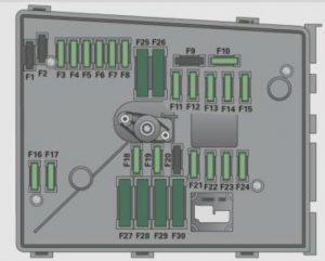
KIA Sportage (2000) – fuse box diagram

KIA Sportage (2000) – fuse box diagram

Year of production: 2000

Engine compartment

KIA Sportage - fuse box diagram - engine compartment
KIA Sportage – fuse box diagram – engine compartment
Description Ampere rating [A] Protected component
FUEL INJ 30 Fuel injection system
ADD 30 A/C condenser fan
MAIN 80 For protection of all circuit
BTN 60 Brake lights, license plate lights, dome light, hazard lights
IGN 30 Ignition
P/WIN 40 Power windows
MAIN 15 Fuel pump injectors, main relay, fuel pump relay
ABS 30 Anti-lock brake system
HEAD 20 Headlight

Passenger Compartment Fuse Panel Description (Driver’s Side Kick Panel)

KIA Sportage - fuse box diagram - driver's kick side panel
KIA Sportage – fuse box diagram – driver’s kick side panel
Description Ampere rating [A] Protected component
P/WINDOW 30 Power windows
HEATER 30 Blower fan
MEMORY 15
TAIL 10 Taillights, parking flights, radio illumination
HAZARD 15 Hazard warning lights
D/LOCK 30 Auto door lock
STOP 15 Brake lights
HORN 10 Horn
ROOM 10 Interior lights
DEF 20 Rear defroster
ST.SIGM 10 Side turn signal lights
F/PUMP 10 Fuel pump
(RR WIPER) 15 Air conditioner, rear wiper
ECU 10 Engine control unit
CIGAR 15 Cigarette lighter, power mirrors
RADIO 10 Radio, clock
ENG 15
METER 10 Instrument restraint system
TURN 10 Lights assembly
O2 SEN1 10 Oxygen sensor
O2 SEN2 10 Oxygen sensor

WARNING: Terminal and harness assignments for individual connectors will vary depending on vehicle equipment level, model, and market.
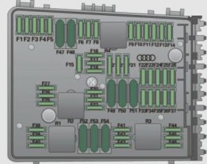
KIA Venga (2013 – 2014) – fuse box diagram

KIA Venga (2013 – 2014) – fuse box diagram

Year of production: 2013, 2014

Inner fuse panel

Description Ampere rating [A] System Protected component
25 POWER WINDOW Left Power Window
25 POWER WINDOW Right Power Window
10 OUTSIDE MIRROR HEATED Outside Mirror Defroster
10 BLOWER Air Conditioning System, ECU
20 DOOR LOCK Door Lock/Unlock
20 SUNROOF Sunroof
15 SAFETY POWER WINDOW Safety Power Window (Driver)
10 FOLDING MIRROR Outside Mirror Folding Switch, Center Facia Switch
10 TAIL LAMP Left Tail Light
10 TAIL LAMP Right Tail Light
10 START Start Motor Relay
15 HAZARD WARNING SIGNAL Center Facia Switch
25 POWER DISTRIBUTION
MODULE
Smk Unit
10 POWER DISTRIBUTION
MODULE
Smk Unit, SSB
MDPS2 10 MOTOR DRIVER POWER
STEERING
MDPS
BRAKE SW 10 STOP SWITCH STOP SWITCH
15 TRANSMISSION
CONTROL UNIT
Speed In Sensor, Speed Out Sensor, Speed Sensor, Inhibitor Switch
15 IGNITION COIL Ignition Coil, Condensor
10 IGNITION HLLD Switch, HLLD Actuator, BCM, Air Conditioning System, Sunroof
25 WINDSCREEN WIPING
SYSTEM (CONTINUOUS)
Front Wiper Motor Relay, Multi Function Switch Wiper
10 FRONT FOG LAMP Front Fog Lamp, BCM
10 REAR FOG LAMP Rear Fog Lamp, BCM
10 ROOM LAMP Room Lamp Switch, MUT
15 STOP LAMP Stop Switch, BCM
10 CLUSTER Cluster, BCM, Digtal Clock
10 IGNITION Audio,TPMS, Center Facia Switch
10 ANTI-LOCK BRAKE SYSTEM Yaw Rate Sensor, ABS(ESP),ESP Switch
10 B/UP LP Back Up Switch
10 ELECTRONIC (ENGINE)
CONTROL UNIT
ECU, AFS
10 RAIN SENSOR
(PTC HEATER )
Rain Sensor Relay (PTC, Fuel Filter Heater)
10 POWER DISTRIBUTION
MODULE
Smart key Unit, SSB
15 FRONT HEAT RAYS JOIN
GLASS
Front Deicer, BCM
15 POWER OUTLET Front Power Outlet
25 POWER OUTLET Rear Power Outlet, Center Power Outlet
10 IGNITION Audio, Digtal Clock
10 AIR BAG INDICATOR Cluster (Air Bag Indicator)
10 AIR BAG ACU
10 DIRECTION INDICATOR
TURN SIGNAL LAMP
Multi Function Switch Light
10 HEADLAMP HI
INDICATOR
Cluster
15 WIPER SYSTEM RR Rear Wiper Motor, Rain Sensor, Multi Function Switch Wiper
15 SEAT HEATER Center Facia Switch
20 AUDIO Audio
10 LUGGAGE LP Luggage Lamp


Engine compartment fuse panel

Description Fuse rating System Protected component
50 IGNITION Start Sol, IGN_SW
50 BATTERY I/P Junction(Stop Lamp 15A,Tail Lamp Relay, Room Lamp, Luggage 10A,Tail Lamp LH 10A, Tail Lamp RH 10A, FOG LP FRT 10A, FOG LP RR 10A)
30 FUEL FILTER HEATER Fuel Filter Heater (Diesel)
125 ALTERNATOR Alternator
150
40 ANTI-LOCK BRAKE SYSTEM ABS, ESP
40 REAR HEAT RAYS JOIN
GLASS
I/P Junction(Rear Heater Relay, Heated Mirror 10A)
40 BLOWER Blower Motor
MDPS1 80 MOTOR DRIVEN POWER
STEERING
MDPS(Motor Driven Power Steering)
40 IGNITION Ignition Switch (IG1, Accessory)
40 COOLING FAN Cooling Fan Relay(High), Cooling Fan Relay(Low)
30 ELECTRONIC (ENGINE)
CONTROL UNIT
“Main Relay, ECU 4 10A, ECU 1 20A, ECU 3 10A, Sensor 10A, Injector 15A”
50 BATTERY “I/P Junction(Hazard 15A, Power Window Relay, Power window LH 25A, Power window RH 25A ,Safety Power window 15A, Sunroof 20A, PDM 3 10A, Deicer 15A, Folding 10A, PDM1 25A, Door Lock 20A)”
10 DAYTIME RUNNING LIGHT BCM
20 HEADLAMP HIGH BEAMS Headlamp High Beam
10 HORN Horn, Burglar Alarm Horn, Battery Sensor
20 HEADLAMP DIPPED BEAMS Headlamp Low Beam
20 FUEL PUMP Fuel Pump Relay (Gasoline)
10 ELECTRONIC (ENGINE)
CONTROL UNIT/AIR HTR
ECU
15 INJECTOR INJECTOR (GASOLINE) E-EGR, WGT, CPS (DIESEL)
SENSOR 10 SENSOR AIR CONDITIONING RELAY, STOP SW, COOLING FAN RELAY (HIGH), COOLING FAN RELAY (LOW)
B/UP LP2 10 B/UP LP RR COMBI LP, ECM MIRROR
10 AIR CONDITIONER Air Conditioning Relay
10 HEADLAMP DIPPED BEAMS Cluster(Low Indicator), Head Lamp Low LH
20 ELECTRONIC(ENGINE)
CONTROL UNIT
ECU
10 HEADLAMP DIPPED BEAMS Head Lamp Low RH
10 ELECTRONIC(ENGINE)
CONTROL UNIT
ENGINE)
CONTROL UNIT
ECU, TCU, GLOW Relay
10 RAIN SENSOR RAIN SENSOR


Engine compartment fuse panel (Diesel engine only)

Description Fuse rating System Protected component
PTC 1 50 PTC Heater 1 PTC Heater 1
PTC 2 50 PTC Heater 2 PTC Heater 2
PTC 3 50 PTC Heater 3 PTC Heater 3
80 GLOW Plug GLOW Plug

WARNING: Terminal and harness assignments for individual connectors will vary depending on vehicle equipment level, model, and market.