KIA Venga (2010 – 2011) – fuse box diagram

KIA Venga (2010 – 2011) – fuse box diagram

Year of production: 2010, 2011

Inner fuse panel

Description Ampere rating [A] Protected component
START 10 Start Motor
ACC 10 Audio, Trip Computer, Outside Mirror Actuator
P/OUTLET FRT 15 Front Power Outlet & Cigar Lighter
P/OUTLET RR 25 Rear Power Outlet, Console Power Outlet
CLUSTER 10 Cluster, BCM, Trip Computer, PDM, Smart Key Unit
T/SIG 10 Multi Function Switch Light
ECU 5 10 ECU, Air Flow Sensor, Fuel Water Sensor
TCU 10 Speed In Sensor, Speed Out Sensor, Speed Sensor
B/UP LP 10 Back Up Switch, Inhibit Switch, RPAS
ABS 3 10 Yaw Rate Sensor, ABS(ESP), ESP Switch
A/BAG 10 ACU
A/BAG IND 10 Cluster(Air Bag Indicator)
IGN COIL 15 Ignition Coil, Condensor
IG1 10 MDPS, Center Facia Switch Module, TPMS, RPAS, Start Motor(ISG)
IG2 10 HLLD Switch, HLLD Actuator, BCM, FATC, Sunroof
WIPER FRT 25 Front Wiper
S/HEATER 15 Seat Warmer
WIPER RR 25 Rear Wiper
PDM 2 10 PDM
HTD MIRR 10 Outside Mirror Defroster
FOG LP FRT 10 Front Fog Light
FOG LP RR 10 Rear Fog Light
AUDIO 20 Audio
ROOM LP 10 Room Lamp Switch
STOP LP 15 Stop Lamp Switch
PDM 1 25 PDM
DEICER 15 Front Deicer
DR LOCK 20 Door Lock/Unlock
FOLD’G MIRR 10 Outside Mirror Folding Switch
SUNROOF 20 Sunroof
TAIL LP LH 10 Left Tail Light
TAIL LP RH 10 Right Tail Light
HAZARD 15 Switch Module
P/WDW LH 25 Left Power Window
P/WDW RH 25 Right Power Window
SAFETY P/WDW 15 Safety Power Window (Driver)


Engine compartment fuse panel

Description Fuse rating Protected component
B+1 50 I/P Junction Box(FOG LP FRT 10A,FOG LP RR 10A, AUDIO 20A, ROOM LP 10A, STOP LP 15A, PDM 1 25A, DEICER 15A, DR LOCK 20A, FOLD’G MIRR 10A, SUNROOF 20A, Relay-Tail Lamp, Fuse- TAIL LP LH 10A, TAIL LP RH 10A)
B+2 50 I/P Junction Box(HAZARD 15A, Relay-Power Window, Fuse-P/WDW LH 25A, P/WDW RH 25A,
SAFETY P/WDW 15A)
C/FAN 40 Cooling Fan Relay(High), Cooling Fan Relay (Low)
ALT 125 Alternator(Gasoline/Diesel)
150
ABS 2 40 ABS, ESP
ABS 1 40 ABS, ESP
RR HTD 40 I/P Junction Box(Rear Heater Relay)
BLOWER 40 Blower Motor
MDPS 80 MDPS(Motor Driving Power Steering)
IG2 40 Ignition Switch(IG2, Start)
ECU 1 20 ECU
F/PUMP 20 Fuel Pump Relay(Gasoline)
IG1 40 Ignition Switch(IG1, Accessory)
H/LP 20 Head Lamp Low Beam
H/LP LO LH 10 Left Head Lamp Low Beam
H/LP LO RH 10 Right Head Lamp Low Beam
H/LP HI 20 Head Lamp High Beam
HORN 10 Horn, Burglar Alarm Horn, Battery Sensor
ECU 4 10 ECU(Gasoline)
FUEL HTR 30 Fuel Filter Heater(Diesel)
A/CON 1 10 Air Conditioning System Relay
A/CON 2 10 Air Conditioning System
ECU 3 10 Immobilizer, Stop Switch, IMV, MPROP
ECU 2 30 ECU 4 10A, Main Relay, Fuse-ECU 1 20A, ECU 3 10A, SENSOR 10A, INJECTOR 15A
DRL 10 Daytime Running Light
SENSOR 10 Gasoline – Air Conditioning System Relay, Cooling Fan Relay(High, Low), Camshaft Position, Sensor, Immobilizer, Canister Purge Solenoid Valve, Oxygen Sensor Up/Down
Diesel – Air Conditioning System Relay, Cooling Fan Relay(High, Low), Lambda Sensor
INJECTOR 15 Gasoline – Injector #1~#4, Fuel Pump Relay, Oil Control Valve
Diesel – Electrical EGR Actuator, Immobilizer, VGT Actuator, Crank Position Sensor, Glow Plug Relay, PTC HTR 1 Relay


Engine compartment fuse panel (Diesel engine only)

Description Fuse rating Protected component
 LOW 80 Glow Plug
PTC HTR 1 50 PTC Heater 1
PTC HTR 2  50 PTC Heater 2
PTC HTR 3 50 PTC Heater 3

WARNING: Terminal and harness assignments for individual connectors will vary depending on vehicle equipment level, model, and market.

Seat Toledo (2012) – fuse box diagram

Seat Toledo (2012) – fuse box diagram

Year of production: 2012

Fuses in the dash panel

Seat Toledo - fuse box diagram - dash panel
Seat Toledo – fuse box diagram – dash panel
Number Component
1 S – ignition
2 START-STOP
3 Instrument panel, headlight range control, telephone, oil level sensor
4 ABS/ESC control unit
5 Petrol engine: cruise control
6 Reverse light (manual gearbox)
7 Switch, engine control unit, automatic gearbox
8 Brake switch, clutch switch, cooling fan
9 Heating control panel, air conditioning control unit, parking aid, electric window riser, radiator fan, windscreen wiper jets
10 DC-DC converter
11 Exterior mirror control
12 Towing bracket control unit
13 Automatic gearbox control unit, automatic gear selector
14 Headlight range control
15
16 Power steering, speed sensor, engine control unit
17 Radio (START-STOP ) daytime driving light
18 Heated mirrors
19 Ignition inlet
20 Engine control unit, fuel pump control unit, fuel pump
21 Reverse light (automatic gearbox), fog lights with CORNER function
22 Heating control panel, control unit of the climate control, telephone, general instrument panel, steering wheel angle sensor, multifunction steering wheel, automatic gearbox key lock
23 Interior lighting, glove compartment and luggage compartment lighting, side lights
24 Central control unit for the vehicle
25
26 Rear window wiper
27
28 Petrol engine: AKF valve, additional heating
29 Injection, coolant pump
30 Fuel pump, ignition, cruise control
31 Lambda probe
32 High-pressure fuel pump, pressure valve
33 Engine control unit
34 Engine control unit, vacuum pump
35 Button backlighting, number plate lighting, parking lights, headlight washers
36 Main beams
37 Rear fog lights, DC/DC converter
38 Fog lights
39 Heater blower
40
41 Heated front seats
42 Heated rear window
43 Horn
44 Windscreen wipers
45 Rear lid lock, central locking system
46 Alarm
47 Cigarette lighter, luggage compartment power socket
48 ABS
49 Turn signals, brake lights
50 DC-DC converter, radio
51 Electric window riser (driver + rear left-hand side)
52 Electric window riser (front passenger + rear right-hand side)
53 Windscreen wash system
54 START-STOP general instrument panel, module below steering wheel, multifunction steering wheel
55 Automatic gearbox control unit
56 Headlight washer
57 Dipped beam headlight (left side)
58 Dipped beam headlight (right side)


Fuses in the engine compartment (version 1 and version 2)

Seat Toledo - fuse box diagram - engine compartment
Seat Toledo – fuse box diagram – engine compartment
Number Component
1 Alternator
2
3 Interior (version 1)
Fuse block power (version 2)
4 Additional electric heating (version 1)
Interior (version 2)
5 Interior
6 Radiator fan, glow plug system control unit
7 Electric-hydraulic power steering
8 ABS
9 Radiator fan
10 Automatic gearbox
11 ABS
12 Central control unit
13 Additional electric heating

WARNING: Terminal and harness assignments for individual connectors will vary depending on vehicle equipment level, model, and market.
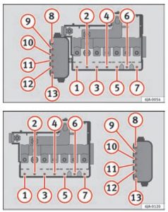
Seat Toledo (2008) – fuse box diagram

Seat Toledo (2008) – fuse box diagram

Year of production: 2008

Fuses on left side of dash panel

Number Component Ampers
1
2
3
4
5
6
7
8
9 Airbag 5
10 RSE input (roof screen) 10
11
12 Left xenon headlight 10
13 Heating controls / ESP, ASR switch/ Reverse/ Preinstallation of telephone/Tomtom navigator 5
14 ABS/ESP switchboard / Engine / Headlights / Trailer switchboard / Light switch / Instrument panel 10
15 Headlight regualtion switchboard / Heated wipers / Instrument lights / Diagnosis Switchboard 10
16 Right xenon headlight 10
17 Engine management 10
18
19
20 Park Pilot (Parking assistant) / Gear lever/ ESP switchboard 10
21 Cable control unit 7,5
22 Volumetric alarm sensor/ Alarm horn 5
23 Diagnosis/ Rain sensor/ Lights switch 10
24 15
25 Switchboard coupling automatic gearbox 20
26 Vacuum pump 20
27 RSE input (roof screen) 10
28 Windscreen washer motor/ Cable control unit 20
29
30 Cigarette lighter / socket 20
31
32
33 Heater 40
34
35
36 Engine management 10
37 Engine management 10
38 Engine management 10
39 Trailer control unit (coupling) 15
40 Trailer control unit (indicators, brakes and left side) 20
41 Trailer control unit (fog light, reversing light and right side) 20
42
43 Trailer pre-installation 40
44 Rear window heater 25
45 Electric windows (front) 30
46 Rear electric windows 30
47 Engine (Fuel control unit, petrol relay) 15
48 Convenience controls 20
49 Heating controls 40
50 Heated seats 30
51 Sunroof 20
52 Headlight washer system 20
53
54 Taxi (metre power supply) 5
55
56 Taxi (taximeter power supply) 15
57
58 Central locking control unit 30


Fuses layout, engine compartment, left part

Number Component Ampers
1 Windscreen wipers 30
2 5
3 Cable control unit 5
4 ABS 30
5 AQ gearbox 15
6 Instrument panel/Steering column 5
7 Ignition key 40
8 Radio 15
9 Telephone/Tomtom navigator 5
10 Engine management 5
Engine management 10
11
12 Electronic control unit 10
13 Petrol injection module supply 25
Diesel injection module supply 30
14 Coil 20
15 Engine management 5
Pump relay 10
16 Right lighting 40
17 Horn 15
18
19 Clean 30
20
21 Lambda probe 15
22 Brake pedal, speed sensor 5
23 Engine management 5
Engine management 10
Engine management 15
24 AKF, gearbox valve 10
25 ABS pump 40
26 Left lighting 40
27 Engine management 40
Engine management 50
28
29 Electric windows (front and back) 50
Electric windows (front) 30
30 Ignition key 40

Position in engine compartment: side box

Number Component Ampers
B1 Alternator < 140 W 150
Alternator > 140 W 200
C1 Power steering servo 80
D1 Multi-terminal voltage supply “30”. Internal fuse box 100
E1 Ventilator > 500 W 80
Ventilator < 500 W 50
F1 PTCs (Supplementary electrical heating using air) 80
G1 PTC (Supplementary electrical heating using air) 40
H1 Central locking control unit

WARNING: Terminal and harness assignments for individual connectors will vary depending on vehicle equipment level, model, and market.

Seat Toledo (2007) – fuse box diagram

Seat Toledo (2007) – fuse box diagram

Year of production: 2007

Fuses on left side of dash panel

Number Component Ampers
1
2
3
4
5
6
7
8
9 Airbag 5
10 RSE input (roof screen)
11
After-sales kit 5
12 Left xenon headlight 10
13 Heating controls / ESP, ASR switch/ Reverse/ Preinstallation of telephone/Tomtom navigator 5
14 ABS/ESP switchboard / Engine / Headlights / Trailer switchboard / Light switch / Instrument panel 10
15 Headlight regualtion switchboard / Heated wipers / Instrument lights / Diagnosis Switchboard 10
16 Right xenon headlight 10
17 D2L Engine (2.0l 147 kW 4-speed TFSI) 10
18
19
20 Park Pilot (Parking assistant) / Gear lever/ ESP switchboard 10
21 Cable control unit 7,5
22 Volumetric alarm sensor/ Alarm horn 5
23 Diagnosis/ Rain sensor/ Lights switch 10
24 Preinstalled towing hook kit (assisted solution) 15
25 Switchboard coupling automatic gearbox 20
26 Vacuum pump 20
27 RSE input (roof screen) 10
28 Windscreen washer motor/ Cable control unit 20
29
30 Cigarette lighter / socket 20
31
32
33 Heater 40
34
35
36 2.0 l 147 kW engine 10
37 2.0 l 147 kW engine 10
38 2.0 l 147 kW engine 10
39 Trailer control unit (coupling) 15
40 Trailer control unit (indicators, brakes and left side) 20
41 Trailer control unit (fog light, reversing light and right side) 20
42
43 Trailer pre-installation 40
44 Rear window heater 25
45 Electric windows (front) 30
46 Rear electric windows 30
47 Engine (Fuel control unit, petrol relay) 15
48 Convenience controls 20
49 Heating controls 40
50 Heated seats 30
51 Sunroof 20
52 Headlight washer system 20
53 Towing ring kit (assistance solution) 20
54 Taxi (metre power supply) 5
55 Towing ring kit (assistance solution) 20
56 Taxi (taximeter power supply) 15
57
58 Central locking control unit 30


Fuses layout, engine compartment, left part

Number Component Ampers
1 Windscreen wipers 30
2 Steering column 5
3 Cable control unit 5
4 ABS 30
5 AQ gearbox 15
6 Instrument panel 5
7  —
8 Radio 15
9 Telephone/Tomtom navigator 5
10 Main relay in the FSI / diesel engine compartment / injection module supply 5
Main relay in the engine compartment D2L (2.0 FSI 147 kW) 10
11
12 Gateway 10
13 Petrol injection module supply 25
Diesel injection module supply 30
14 Coil 20
15 Engine T71 / 20 FSI 5
Pump relay 10
16 ABS pump 30
17 Horn 15
18
19 Clean 30
20
21 Lambda probe 15
22 Brake pedal, speed sensor 5
23 DiagnEngine 1.6, main relay (relay n° 100) 5
T 71 diesel EGR 10
2.0 D2L High-pressure fuel pump 15
24 AKF, gearbox valve 10
25 Right lighting 40
26 Left lighting 40
1.6 SLP engine 40
1.9 TDI Glow plug relay 50
27 KL15 40
28 Windscreen washer motor/ Cable control unit 20
29 Electric windows (front and back) 50
Electric windows (front) 30
30 X – relief relay 40

Position in engine compartment: side box

Number Component Ampers
B1 Alternator < 140 W 150
Alternator > 140 W 200
C1 Power steering 80
D1 Multi-terminal voltage supply “30”. Internal fuse box 100
E1 Ventilator > 500 W 80
Ventilator < 500 W 50
F1 PTCs (Supplementary electrical heating using air) 80
G1 PTC (Supplementary electrical heating using air) 40
H1 Central locking control unit (4F8 with autolock)

WARNING: Terminal and harness assignments for individual connectors will vary depending on vehicle equipment level, model, and market.

Seat Toledo (2006) – fuse box diagram

Seat Toledo (2006) – fuse box diagram

Year of production: 2006

Fuses on left side of dash panel

Number Component Ampers
1
2
3
4
5
6
7
8
9 Airbag 5
10
11
After-sales kit 5
12 Left hand side xenon headlight 10
13 Heating controls/ESP switch, ASR/Reverse gear/Telephone installation 5
14 ABS Control unit/ESP/ Engine/ Headlights/ Trailer control unit/lights switch/ Instrument panel 10
15 Headlight adjustment control unit/ Heated windscreens/ Instrument lighting/ Control unit diagnosis 10
16 Right hand side xenon headlight 10
17 Engine D2L (2.0l 147 kW 4 speed TFSI) 10
18
19
20 Park Pilot (parking aid) / Gear selector lever/ Control unit ESP 10
21 Cable control unit 7,5
22 Volumetric alarm sensor/ Alarm horn 5
23 Diagnosis/ Rain sensor/ Lights switch 10
24
25 Automatic gearbox control unit interface 20
26 Vacuum pump 20
27
28 Windscreen washer motor/ Cable control unit 20
29
30 Cigarette lighter / socket 20
31
32
33 Heater 40
34
35
36 2.0 l 147 kW engine 10
37 2.0 l 147 kW engine 10
38 2.0 l 147 kW engine 10
39 Trailer control unit (coupling) 15
40 Trailer control unit (indicators, brakes and left side) 20
41 Trailer control unit (fog light, reversing light and right side) 20
42 Towing ring kit (assistance solution) 15
43
44 Rear window heater 25
45 Front electric windows 30
46 Rear electric windows 30
47 Engine (gauge, fuel relay) 15
48 Convenience controls 20
49 Heating controls 40
50 Heated seats 30
51 Sunroof 20
52 Headlight washer system 20
53 Towing ring kit (assistance solution) 20
54 Taxi (metre power supply) 5
55 Towing ring kit (assistance solution) 20
56 Taxi (radio transmitter power supply) 15
57
58 Central locking control unit 30


Fuses layout, engine compartment, left part

Number Component Ampers
1
2
3
4
5
6
7
8 Airbag 5
9
10
11
Assistance case/ After sales kit / Fitting subsequent devices 5
12 Left hand side xenon headlight 10
13 Heating controls/ ESP switch, ASR/Reverse gear/Telephone installation 5
14 ABS Control unit/ESP/ Engine/ Headlights/ Trailer control unit/lights switch/ Instrument panel 10
15 Headlight adjustment control unit/ Heated windscreens/ Instrument lighting/ Control unit diagnosis 10
16 Right hand side xenon headlight 10
17 Engine D2L (2.0l 147 kW 4 speed TFSI) 10
18
19
20 Park Pilot (parking aid) / Gear selector lever/ Control unit ESP 10
21 Cable control unit 7,5
22 Volumetric alarm sensor/ Alarm horn 5
23 Diagnosis/ Rain sensor/ Lights switch 10
24
25 Automatic gearbox control unit interface 20
26 Vacuum pump 20
27
28 Windscreen washer motor/ Cable control unit 20
29
30 Cigarette lighter / socket
31
32
33 Heater 40
34
35
36 2.0 l 147 kW engine 10
37 2.0 l 147 kW engine
38 2.0 l 147 kW engine
39 Trailer control unit (coupling) 15
40 Trailer control unit (indicators, brakes and left side) 20
41 Trailer control unit (fog light, reversing light and right side) 20
42 Towing ring kit (assistance solution) 15
43
44 Rear window heater 25
45 Front electric windows 30
46 Rear electric windows 30
47 Engine (gauge, fuel relay) 15
48 Convenience controls 20
49 Heating controls 40
50 Heated seats 30
51 Sunroof 20
52 Headlight washer system 20
53 Towing ring kit (assistance solution) 20
54 Taxi (metre power supply) 5
55 Towing ring kit (assistance solution) 20
56 Taxi (radio transmitter power supply) 15
57
58 Central locking control unit 30

Position in engine compartment: side box

Number Component Ampers
B1 Alternator < 140 W 150
Alternator > 140 W 200
C1 Power steering 80
D1 Multi-terminal voltage supply “30”. Internal fuse box 100
E1 Ventilator > 500 W 80
Ventilator < 500 W 50
F1 PTCs (Supplementary electrical heating using air) 100
G1 Trailer fuse voltage supply in internal fuse box 50
H1 Central locking control unit (4F8 with autolock)

WARNING: Terminal and harness assignments for individual connectors will vary depending on vehicle equipment level, model, and market.

Seat Toledo (2005) – fuse box diagram

Seat Toledo (2005) – fuse box diagram

Year of production: 2005

Fuses on left side of dash panel

Number Component Ampers
1 Electro-chromatic mirror / relay 50 5
2 Engine control unit 5
3 Lights switch / Headlight control unit / Right hand side headlight / Telephone 5
4 Telephone pre-installation 5
5 Flow meter, frequency tube 10
6 Airbag 5
7
8
9 Power steering 5
10 Diagnosis, reverse gear switch 5
11 Heated windscreen 5
12 FSI measure 10
13 Trailer control unit 5
14 ESP/TCP, ABS/ESP control unit 5
15 Automatic gearbox 5
16 Heating controls / Climatronic / Pressure sensor / Heated seats 10
17 Engine 7,5
18
19
20 Engine fuse box supply 5
21 Gear lever 5
22
23 Brake lights 5
24 Diagnosis / lights switch 10
25 Vacuum pump 20
26 Engine supply coupling 10
27 Automatic gearbox 20
28 Light switch 5
29 Rear window wiper motor 15
30 Heating operation 5
31 Cable control unit 15
32 Jets 5
33 Heater 40
34
35
36
37
38
39 Trailer control unit (coupling) 15
40 Trailer control unit (indicators, brakes and left side) 20
41 Trailer control unit (fog light, reversing light and right side) 20
42 Console electrical socket 15
Electrical socket, rear 30
43 Fuel control unit 15
44 Alarm horn and interior monitor sensor 5
45
46 Cable control unit 7,5
47 Cigarette lighter 25
48 Seats 10
49 Door locks 10
50 Central locking control unit 25
51 Sunroof 20
52 Cable control unit 25
53 Headlight washer system 20
54 Park Pilot 5
55
56 Climatronic heater motor 40
57 Door control unit 30
58 Door control unit 30

Location under steering wheel, on relay carrier

Number Component Ampers
Air Door control units (electric windows/ electric mirrors/ central locking) 30


Fuses layout, engine compartment, left part

Number Component Ampers
1 Clean 30
2 Steering column 5
3 Cable control unit 5
4 ABS 30
5 AQ gearbox 15
6 Kombi 5
7
8 Radio 15
9 Telephone 5
10 Main relay in the FSI / diesel engine compartment / injection module supply 5
Main relay in the engine compartment D2L (2.0 FSI 147 kW) 10
11
12 Gateway 5
13 Petrol injection module supply 25
Diesel injection module supply 20
14 Coil 20
15 Engine T71 / 20 FSI 5
Pump relay 10
16 ADS pump 30
17 Horn 15
18
19 Clean 30
20
21 Lambda probe 15
22 Brake pedal, speed sensor 5
23 Engine 1.6, main relay (relay n° 100) 5
T 71 diesel EGR 10
2.0 D2L High-pressure fuel pump 15
24 ARF, change valve 10
25 Right lighting 40
26 Left lighting 40
27 1.6 SLP engine 40
1.9 TDI Glow plug relay 50
28 KL15 40
29 Electric windows (front and back) 50
Electric windows (front) 30
30 KLX 40

Position in engine compartment: side box

Number Component Ampers
B1 Alternator < 140 W 150
Alternator > 140 W 200
C1 Power steering 80
D1 PTCs (Supplementary electrical heating using air) 100
E1 Ventilator > 500 W / Ventilator < 500 W 80
50
F1 Multi-terminal voltage supply “30”. Internal fuse box 100
G1 Trailer fuse voltage supply in internal fuse box 50
H1

WARNING: Terminal and harness assignments for individual connectors will vary depending on vehicle equipment level, model, and market.

Seat Leon (2010 – 2012) – fuse box diagram

Seat Leon (2010) – fuse box diagram

Year of production: 2010, 2011, 2012

Fuses on left side of dash panel

Number Component Ampers
1 Diagnosis Switchboard/ Instrument lighting/Headlight control switchboard/ Flow meter/Heated wipers/ Engine management/ AFS Headlamps 10
2 Engine control unit/ ABS-ESP switchboard/ Automatic gearbox/ Instrument panel/ Trailer switchboard/Light switch / Brake sensor/ Power
steering/ Right and left headlights
10
3 Airbag 5
4 Heating/ Reverse switch/ ASR-ESP switch/ Electrochrome mirror/ Park Pilot/ Oil level sensor 5
5 Right xenon headlight 10
6 Left xenon headlight 10
7
8 Trailer hook pre-installation assistant 5
9
10
11
12 Central locking 15
13 Diagnosis/ Light switch/ Rain sensor/ Heated rear window 10
14 Automatic gearbox / Heating/ ESP switchboard/ Automatic gearbox lever 5
15
16
17 Alarm 5
18 Kombi / levers with START STOP 5
19 Fog light aid 20
20 Navigation/radio with START STOP 15
21 Engine management 10
22 Fan switch 40
23 Electric windows (front) 30
24 Body Control Unit 20
25 Heated rear window 25
26 Rear electric windows 30
27 Engine (fuel control unit/pump relay) 15
28 Convenience controls 30
29
30
31 Vacuum pump 20
32
33 Sunroof 25
34 Comfort switchboard/Central locking system 25
35
36 Headlight washer system 20
37 Heated seats 30
38 Engine management 10
39 Telephone with START STOP 10
40 Fan switch 40
41 Rear wiper motor / Switchboard wiring 20
42 12 V socket/ Cigarette lighter 15
43 Trailer bracket preinstallation 15
44 Trailer bracket preinstallation 20
45 Trailer bracket preinstallation 15
46
47 Engine management 10
48 Engine management 10
49

Fuses layout, engine compartment, left part

Number Component Ampers
1 Windscreen wipers 30
2 DQ200 gearbox 30
3 Cable control unit 5
4 ABS 20
5 AQ gearbox 15
6 Instrument panel/Steering column 5
7 Ignition key 40
8 Radio 15
9 Telephone/TomTom Navigator 5
10 Engine management 5
Engine management 10
11
12 Electronic control unit 5
13 Petrol injection module supply 15
Diesel injection module supply 30
14 Coil 20
15 Engine management 5
Pump relay 10
16 Right lighting 30
17 Horn 15
18
19 Clean 30
20 Water pump 10
Pressure sensor pump for 1.8 engine 20
21* Lambda probe 15
22 Brake pedal, speed sensor 5
23* Engine management 5
Engine management 10
Engine management 15
24 AKF, gearbox valve 10
25* ABS pump 40
26 Left lighting 30
27* Engine management 40
Engine management 50
28
29* Electric windows (front and rear) 50
Electric windows (front) 30
30 Ignition key 50
* Ampere rating according to motorisation

WARNING: Terminal and harness assignments for individual connectors will vary depending on vehicle equipment level, model, and market.

Seat Leon (2009) – fuse box diagram

Seat Leon (2009) – fuse box diagram

Year of production: 2009

Fuses on left side of dash panel

Number Component Ampers
1 Diagnosis Switchboard/ Instrument lighting/Headlight control switchboard/ Flow meter/Heated wipers/ Engine management/ AFS Headlamps 10
2 Engine control unit/ ABS-ESP switchboard/ Automatic gearbox/ Instrument panel/ Trailer switchboard/Light switch / Brake sensor/ Power
steering/ Right and left headlights
10
3 Airbag 5
4 Heating/ Reverse switch/ ASR-ESP switch/ Electrochrome mirror/ Park Pilot/ Oil level sensor 5
5 Right xenon headlight 10
6 Left xenon headlight 10
7
8 Trailer hook pre-installation assistant 5
9
10
11
12 Central locking 15
13 Diagnosis/ Light switch/ Rain sensor/ Heated rear window 10
14 Automatic gearbox / Heating/ ESP switchboard/ Automatic gearbox lever 5
15
16
17 Alarm 5
18 Kombi / levers with START STOP 5
19 Fog light aid 20
20 Navigation/radio with START STOP 15
21 Engine management 10
22 Fan switch 40
23 Electric windows (front) 30
24 Body Control Unit 20
25 Rear window heater 25
26 Rear electric windows 30
27 Engine (fuel control unit/pump relay) 15
28 Convenience controls 30
29
30 Automatic gearbox 20
31 Vacuum pump 20
32
33 Sunroof 25
34 Comfort switchboard/Central locking system 25
35
36 Headlight washer system 20
37 Heated seats 30
38 Engine management 10
39 Telephone with START STOP 10
40 Fan switch 40
41 Rear wiper motor / Switchboard wiring 20
42 12 V socket/ Cigarette lighter 15
43 Trailer bracket preinstallation 15
44 Trailer bracket preinstallation 20
45 Trailer bracket preinstallation 15
46
47 Engine management 10
48 Engine management 10
49

Fuses layout, engine compartment, left part

Number Component Ampers
1 Windscreen wipers 30
2 DQ200 gearbox 30
3 Cable control unit 5
4 ABS 20
5 AQ gearbox 15
6 Instrument panel/Steering column 5
7 Ignition key 40
8 Radio 15
9 Telephone/TomTom Navigator 5
10 Engine management 5
Engine management 10
11
12 Electronic control unit 5
13 Petrol injection module supply 15
Diesel injection module supply 30
14 Coil 20
15 Engine management 5
Pump relay 10
16 Right lighting 30
17 Horn 15
18
19 Clean 30
20 Water pump 10
Pressure sensor pump for 1.8 engine 20
21* Lambda probe 15
22 Brake pedal, speed sensor 5
23* Engine management 5
Engine management 10
Engine management 15
24 AKF, gearbox valve 10
25* ABS pump 40
26 Left lighting 30
27* Engine management 40
Engine management 50
28
29 Electric windows (front and rear) 50
Electric windows (front) 30
30 Ignition key 50
* Ampere rating according to motorisation

WARNING: Terminal and harness assignments for individual connectors will vary depending on vehicle equipment level, model, and market.

Seat Leon (2008) – fuse box diagram

Seat Leon (2008) – fuse box diagram

Year of production: 2008

Fuses on left side of dash panel

Number Component Ampers
1 Diagnosis Switchboard/Instrument lights / Headlights switchboard/ Flowmeter/ Heated wipers 10
2 Engine control unit/ ABS-ESP switchboard/ Automatic gearbox/ Instrument panel/ Trailer switchboard/ Light switch / Brake sensor/ Power steering/ Right and left headlights 5
3 Airbag 5
4 Heating/Reverse gear switch (ASR-ESP switch/Telephone/Jets/Electrochromic mirror/Tomtom route finder 5
5 Right xenon headlight 5
6 Left xenon headlight 5
7
8
9
10
11
12 Central locking 10
13 Diagnosis/ Lights switch/ Rain sensor 10
14 Automatic gearbox / Heating/ ESP switchboard/ Automatic gearbox lever 5
15 Cable control unit 7,5
16
17 Alarm 5
18
19
20
21 Engine management 10
22 Fan switch 40
23 Electric windows (front) 30
24
25 Rear window heater 25
26 Rear electric windows 30
27 Engine (fuel control unit/pump relay) 15
28 Convenience controls 25
29
30 Automatic gearbox 20
31 Vacuum pump 20
32
33 Sunroof 30
34 Convenience controls 25
35
36 Headlight washer system 20
37 Heated seats 30
38 Engine management 10
39
40 Fan switch 40
41 Rear wiper motor / Switchboard wiring 15
42 12 V socket/ Cigarette lighter 15
43 Trailer bracket preinstallation 15
44 Trailer bracket preinstallation 20
45 Trailer bracket preinstallation 15
46
47 Engine management 10
48 Engine management 10
49

Fuses layout, engine compartment, left part

Number Component Ampers
1 Clean 30
2
3 Cable control unit 5
4 ABS 30
5 AQ gearbox 15
6 Kombi / Steering column 5
7 Ignition key 40
8 Radio 15
9 Telephone/TomTom Navigator 5
10 Engine management 5
Engine management 10
11
12 Gateway 5
13 Petrol injection module supply 25
Diesel injection module supply 30
14 Coil 20
15 Engine management 5
Fuel pump relay 10
16 Right lighting 30
17 Horn 15
18
19 Clean 30
20
21 Lambda probe 15
22 Brake pedal, speed sensor 5
23 Engine management 5
Engine management 10
Engine management 15
24 ARF, change valve 10
25 ABS pump 40
26 Left lighting 40
27 Engine management 40
Engine management 50
28
29 Electric windows (front and rear) 50
Electric windows (front) 30
30 Ignition key 40

Position in engine compartment: side box

Number Component Ampers
B1 Alternator < 140 W 150
Alternator > 140 W 200
C1 Power steering 80
D1 Multi-terminal voltage supply “30”. Internal fuse box 100
E1 Ventilator < 500 W / Ventilator > 500 W 50
80
F1 PTCs (Supplementary electrical heating using air) 80
G1 PTC (Supplementary electrical heating using air) 40
H1 Central locking control unit


WARNING: Terminal and harness assignments for individual connectors will vary depending on vehicle equipment level, model, and market.

Seat Leon (2007) – fuse box diagram

Seat Leon (2007) – fuse box diagram

Year of production: 2007

Fuses on left side of dash panel

Number Component Ampers
1 Diagnosis Switchboard/Instrument lights / Headlights switchboard/ Flowmeter/ Heated wipers 10
2 Engine control unit/ ABS-ESP switchboard/ Automatic gearbox/ Instrument panel/ Trailer switchboard/ Light switch / Brake sensor/ Power steering/ Right and left headlights 5
3 Airbag 5
4 Heating/ Reverse switch/ ASR-ESP switch/ Telephone/ Nozzles/ Electrochrome anti-dazzle mirror/ Tomtom
navigator
5
5 Right xenon headlight 5
6 Left xenon headlight 5
7
8 Trailer pre-installation kit (assistance solution) 5
9
10
11
12 Central locking 10
13 Diagnosis/ Lights switch/ Rain sensor 10
14 Automatic gearbox / Heating/ ESP switchboard/ Automatic gearbox lever 5
15 Cable control unit 7,5
16
17 Alarm 5
18
19 Fog kit (assisted solution)
20
21 D2L Engine (2.0l 147 kW 4-speed TFSI) 10
22 Blower control 40
23 Electric windows (front) 30
24
25 Rear window heater 25
26 Rear electric windows 30
27 Engine (fuel control unit/pump relay) 15
28 Convenience controls 25
29
30 Automatic gearbox 20
31 Vacuum pump 20
32
33 Sunroof 30
34 Convenience controls 25
35
36 Headlight washer system 20
37 Heated seats 30
38 D2L Engine (2.0 l 147 kW 4-speed TFSI) 10
39 20
40 Blower control 40
41 Rear wiper motor / Switchboard wiring 15
42 12 V socket/ Cigarette lighter 15
43 Trailer bracket pre-installation 15
44 Trailer bracket pre-installation 20
45 Trailer bracket pre-installation 15
46
47 Engine D2L (2.0 litre 147 kW 4 speed TFSI) 10
48 Engine D2L (2.0 litre 147 kW 4 speed TFSI) 10
49

Fuses layout, engine compartment, left part

Number Component Ampers
1 Clean 30
2 Steering column 5
3 Cable control unit 5
4 ABS 30
5 AQ gearbox 15
6 Instrument panel 5
7
8 Radio 15
9 Telephone 5
10 Main relay in the FSI / diesel engine compartment / injection module supply 5
Main relay in the engine compartment D2L (2.0 FSI 147 kW) 10
11
12 Gateway 5
13 Petrol injection module supply 25
Diesel injection module supply 30
14 Coil 20
15 Engine T71 / 20 FSI 5
Pump relay 10
16 ADS pump 30
17 Horn 15
18
19 Clean 30
20
21 Lambda probe 15
22 Brake pedal, speed sensor 5
23 Engine 1.6, main relay (relay n° 100) 5
T 71 diesel EGR 10
2.0 D2L High-pressure fuel pump 15
24 ARF, change valve 10
25 Right lighting 40
26 Left lighting 40
27 1.6 SLP engine 40
1.9 TDI glow plug relay 50
28 KL15 40
29 Electric windows (front and rear) 50
Electric windows (front) 30
30 X – relief relay 40

Position in engine compartment: side box

Number Component Ampers
B1 Alternator < 140 W 150
Alternator > 140 W 200
C1 Power steering 80
D1 Multi-terminal voltage supply “30”. Internal fuse box 100
E1 Ventilator < 500 W / Ventilator > 500 W 50
80
F1 PTCs (Supplementary electrical heating using air) 100
G1 Trailer fuse voltage supply in internal fuse box 50
H1 Central locking control unit (4F8 with autolock)


WARNING: Terminal and harness assignments for individual connectors will vary depending on vehicle equipment level, model, and market.