Seat Altea (2008) – fuse box diagram

Seat Altea (2008) – fuse box diagram

Year of production: 2008

Fuses on left side of dash panel

Number Electrical equipment Ampere rating [A]
1 Vacant
2 Vacant
3 Vacant
4 Vacant
5 Vacant
6 Vacant
7 Vacant
8 Vacant
9 Airbag 5
10 RSE input (roof screen) 10
11 Vacant
12 Left xenon headlight 10
13 Heating controls / ESP, ASR switch / Reverse / Preinstallation of telephone / Tomtom Navigator 5
14 ABS/ESP switchboard / Engine / Headlights / Trailer switchboard / Light switch / Instrument panel 10
15 Headlight regulation switchboard / Heated wipers / Instrument lights / Diagnosis Switchboard 10
16 Right xenon headlight 10
17 Engine management 10
18 Vacant
19 Vacant
20 Park Pilot (Parking assistant) / Gear lever/ ESP switchboard 10
21 Cable control unit 7,5
22 Volumetric alarm sensor/ Alarm horn 5
23 Diagnosis/Rain sensor/Light switch 10
24 Vacant
25 Switchboard coupling automatic gearbox 20
26 Vacuum pump 20
27 RSE input (roof screen) 10
28 Rear wiper motor / Switchboard wiring 20
29 Vacant
30 Cigarette lighter / socket 20
31 Vacant
32 Vacant
33 Heater 40
34 Vacant
35 Vacant
36 Engine management 10
37 Engine management 10
38 Engine management 10
39 Trailer control unit (coupling) 15
40 Trailer control unit (indicators, brakes and left side) 20
41 Trailer control unit (fog light, reversing light and right side) 20
42 Vacant
43 Trailer pre-installation 40
44 Rear window heater 25
45 Electric windows (front) 30
46 Rear electric windows 30
47 Engine (Fuel control unit, petrol relay) 15
48 Convenience controls 20
49 Heating controls 40
50 Heated seats 30
51 Sunroof 20
52 Headlight washer system 20
53 Vacant
54 Taxi (taxi metre power supply) 5
55 Vacant
56 Taxi (transmitter power supply) 15
57 Vacant
58 Central locking control unit 30

Fuses layout, engine compartment, left part

Number Electrical equipment Ampere rating [A]
1 Windscreen wipers 30
2 Steering column 5
3 Cable control unit 5
4 ABS 30
5 AQ gearbox 15
6 Instrument panel 5
7 Vacant
8 Radio 15
9 Telephone/TomTom Navigator 5
10 Engine management 5
Engine management 10
11 Vacant
12 Electronic control unit 5
13 Petrol injection module supply 25
Diesel injection module supply 30
14 Coil 20
15 Engine management 5
Pump relay 10
16 ABS pump 30
17 Horn 15
18 Vacant
19 Clean 30
20 Vacant
21 Lambda probe 15
22 Brake pedal, speed sensor 5
23 Engine management 5
Engine management 10
Engine management 15
24 ARF, change valve 10
25 Right lighting 40
26 Left lighting 40
27 Engine management 40
Engine management 50
28 Ignition key 40
29 Electric windows (front and back) 50
Electric windows (front) 30
30 Ignition key 40

Position in engine compartment: side box

Fuses

Number Electrical equipment Ampere rating [A]
B1 Alternator < 140 W 150
Alternator > 140 W 200
C1 Power steering servo 80
D1 Multi-terminal voltage supply “30”. Internal fuse box 100
E1 Ventilator > 500 W 80
Ventilator < 500 50
F1 PTCs (Supplementary electrical heating using air) 80
G1 PTC (Supplementary electrical heating using air) 40
H1 Central locking control unit

WARNING: Terminal and harness assignments for individual connectors will vary depending on vehicle equipment level, model, and market.

Seat Altea (2007) – fuse box diagram

Seat Altea (2007) – fuse box diagram

Year of production: 2007

Fuses on left side of dash panel

Number Electrical equipment Ampere rating [A]
1 Vacant
2 Vacant
3 Vacant
4 Vacant
5 Vacant
6 Vacant
7 Vacant
8 Vacant
9 Airbag 5
10 Vacant
11 Vacant
After-sales kit 5
12 Left hand side xenon headlight 10
13 Heating controls/ESP, ASR switch/Reverse gear/Telephone pre-installation 5
14 ABS/ESP control unit/ Engine/ Headlights/ Trailer control unit/ light switch/ Instrument panel 10
15 Headlight control unit/ Heated windscreens/ Instrument lighting/ Diagnosis control unit 10
16 Right hand side xenon headlight 10
17 D2L Engine (2.0 litre 147 kW 4 speed TFSI) 10
18 Vacant
19 Vacant
20 Park Pilot (Parking aid) / Gear selector lever/ ESP control unit 10
21 Cable control unit 7,5
22 Volumetric alarm sensor/alarm siren 5
23 Diagnosis/Rain sensor/Light switch 10
24 Vacant
25 Automatic gearbox control unit connection 20
26 Vacuum pump 20
27 Vacant
28 Windscreen wiper motor/Cable control unit 20
29 Vacant
30 Cigarette lighter / socket 20
31 Vacant
32 Vacant
33 Heater 40
34 Vacant
35 Vacant
36 2.0 litre 147 kW engine 10
37 2.0 litre 147 kW engine 10
38 2.0 litre 147 kW engine 10
39 Trailer control unit (coupling) 15
40 Trailer control unit (indicators, brakes and left side) 20
41 Trailer control unit (fog light, reversing light and right side) 20
42 Towing kit 15
43 Vacant
44 Rear window heater 25
45 Front electric windows 30
46 Rear electric windows 30
47 Engine (gauge, fuel relay) 15
48 Convenience controls 20
49 Heating controls 40
50 Heated seats 30
51 Sunroof 20
52 Headlight washer system 20
53 Towing kit 20
54 Taxi (taxi metre power supply) 5
55 Towing kit 20
56 Taxi (transmitter power supply) 15
57 Vacant
58 Central locking control unit 30

Fuses layout, engine compartment, left part

Number Electrical equipment Ampere rating [A]
1 Windscreen wipers 30
2 Steering column 5
3 Cable control unit 5
4 ABS 30
5 AQ gearbox 15
6 Instrument panel 5
7 Vacant
8 Radio 15
9 Telephone 5
10 Main relay in the FSI / diesel engine compartment / injection module supply 5
Main relay in the engine compartment D2L (2.0 FSI 147 kW) 10
11 Vacant
12 Gateway 5
13 Petrol injection module supply 25
Diesel injection module supply 30
14 Coil 20
15 Engine T71 / 20 FSI 5
Pump relay 10
16 ADS pump 30
17 Horn 15
18 Vacant
19 Clean 30
20 Vacant
21 Lambda probe 15
22 Brake pedal, speed sensor 5
23 Engine 1.6, main relay (relay n° 100) 5
T 71 diesel EGR 10
2.0 D2L High-pressure fuel pump 15
24 ARF, change valve 10
25 Right lighting 40
26 Left lighting 40
27 1.6 SLP engine 40
1.9 TDI Glow plug relay 50
28 KL15 40
29 Electric windows (front and back) 50
Electric windows (front) 30
30 X – relief relay 40

Position in engine compartment: side box

Fuses

Number Electrical equipment Ampere rating [A]
B1 Alternator < 140 W 150
Alternator > 140 W 200
C1 Power steering 80
D1 Multi-terminal voltage supply “30”. Internal fuse box 100
E1 Ventilator > 500 W 80
Ventilator < 500 50
F1 PTCs (Supplementary electrical heating using air) 100
G1 Trailer fuse voltage supply in internal fuse box 50
H1 Central locking control unit (4F8 with autolock)

WARNING: Terminal and harness assignments for individual connectors will vary depending on vehicle equipment level, model, and market.

Seat Altea (2006) – fuse box diagram

Seat Altea (2006) – fuse box diagram

Year of production: 2006

Fuses box on the left side  of dash panel

Number Electrical equipment Ampere rating [A]
1 Electro-chromatic mirror / relay 50 5
2 Engine control unit 5
3 Lights switch / Headlight control unit / Right hand side headlight / Telephone 5
4 Telephone pre-installation 5
5 Flow meter, frequency tube 10
6 Airbag 5
7 Vacant
8 Vacant
9 Power steering 5
10 Diagnosis, reverse gear switch 5
11 Heated windscreen 5
12 FSI measure 10
13 Trailer control unit 5
14 ESP/TCP, ABS/ESP control unit 5
15 Automatic gearbox 5
16 Heating controls / Climatronic / Pressure sensor / Heated seats 10
17 Engine 7,5
18 Vacant
19 Vacant
20 Engine fuse box supply 5
21 Gear lever 5
22 Vacant
23 Brake lights 5
24 Diagnosis / lights switch 10
25 Vacuum pump 20
26 Engine supply coupling 10
27 Automatic gearbox 20
28 Light switch 5
29 Rear window wiper motor 15
30 Heating operation 5
31 Cable control unit 15
32 Jets 5
33 Heater 40
34 Vacant
35 Vacant
36 Vacant
37 Vacant
38 Vacant
39 Trailer control unit (coupling) 15
40 Trailer control unit (indicators, brakes and left side) 20
41 Trailer control unit (fog light, reversing light and right side) 20
42 Console electrical socket 15
Electrical socket, rear 30
43 Fuel control unit 15
44 Alarm horn and interior monitor sensor 5
45 Vacant
46 Cable control unit 7,5
47 Cigarette lighter 25
48 Seats 30
49 Rear electric windows 30
50 Central locking system control unit (4K3 without autolock) 25
51 Sunroof 20
52 Cable control unit 25
53 Headlight washer system 20
54 Park Pilot 5
55 Vacant
56 Climatronic heater motor 40
57 Door control unit 30
58 Central locking system control unit (4F8 with autolock) 30


Location under steering wheel, on relay carrier

Number Electrical equipment
Air Door control units (electric windows/ electric mirrors/ central locking)

Fuses layout in engine compartment, left part

Number Electrical equipment Ampere rating [A]
1 Clean 30
2 Steering column 5
3 Cable control unit 5
4 ABS 30
5 AQ gearbox 15
6 Kombi 5
7 Vacant
8 Radio 15
9 Telephone 5
10 Main relay in the FSI / diesel engine compartment / injection module supply 5
Main relay in the engine compartment D2L (2.0 FSI 147 kW) 10
11 Vacant
12 Gateway 5
13 Petrol injection module supply 25
Diesel injection module supply 30
14 Coil 20
15 Engine T71 / 20 FSI 5
Pump relay 10
16 ADS pump 30
17 Horn 15
18 Vacant
19 Clean 30
20 Vacant
21 Lambda probe 15
22 Brake pedal, speed sensor 5
23 Engine 1.6, main relay (relay n° 100) 5
T 71 diesel EGR 10
2.0 D2L High-pressure fuel pump 15
24 ARF, change valve 10
25 Right lighting 40
26 Left lighting 40
27 1.6 SLP engine 40
1.9 TDI Glow plug relay 50
28 KL15 40
29 Electric windows (front and back) 50
Electric windows (front) 30
30 KLX 40

Position in engine compartment: side box

Fuses

Number Electrical equipment Ampere rating [A]
B1 Alternator < 140 W 150
Alternator > 140 W 200
C1 Power steering 80
D1 PTCs (Supplementary electrical heating using air) 100
E1 Ventilator > 500 W 80
Ventilator < 500 50
F1 Multi-terminal voltage supply “30”. Internal fuse box 100
G1 Trailer fuse voltage supply in internal fuse box 50
H1 Vacant

WARNING: Terminal and harness assignments for individual connectors will vary depending on vehicle equipment level, model, and market.

Seat Altea (2005) – fuse box diagram

Seat Altea (2005) – fuse box diagram

Year of production: 2005

Fuses box on the left side  of dash panel

Number Electrical equipment Ampere rating [A]
1 Electro-chromatic mirror / relay 50 5
2 Engine control unit 5
3 Lights switch / Headlight control unit / Right hand side headlight / Telephone 5
4 Telephone pre-installation 5
5 Flow meter, frequency tube 10
6 Airbag 5
7 Vacant
8 Vacant
9 Power steering 5
10 Diagnosis, reverse gear switch 5
11 Heated windscreen 5
12 FSI measure 10
13 Trailer control unit 5
14 ESP/TCP, ABS/ESP control unit 5
15 Automatic gearbox 5
16 Heating controls / Climatronic / Pressure sensor / Heated seats 10
17 Engine 7,5
18 Vacant
19 Vacant
20 Engine fuse box supply 5
21 Gear lever 5
22 Vacant
23 Brake lights 5
24 Diagnosis / lights switch 10
25 Vacuum pump 20
26 Engine supply coupling 10
27 Automatic gearbox 20
28 Light switch 5
29 Rear window wiper motor 15
30 Heating operation 5
31 Cable control unit 15
32 Jets 5
33 Heater 40
34 Vacant
35 Vacant
36 Vacant
37 Vacant
38 Vacant
39 Trailer control unit (coupling) 15
40 Trailer control unit (indicators, brakes and left side) 20
41 Trailer control unit (fog light, reversing light and right side) 20
42 Console electrical socket 15
Electrical socket, rear 30
43 Fuel control unit 15
44 Alarm horn and interior monitor sensor 5
45 Vacant
46 Cable control unit 7,5
47 Cigarette lighter 25
48 Seats 30
49 Door locks 10
50 Central locking control unit 25
51 Sunroof 20
52 Cable control unit 25
53 Headlight washer system 20
54 Park Pilot 5
55 Vacant
56 Climatronic heater motor 40
57 Door control unit 30
58 Door control unit 30


Location under steering wheel, on relay carrier

Number Electrical equipment
Air Door control units (electric windows/ electric mirrors/ central locking)

Fuses layout in engine compartment, left part

Number Electrical equipment Ampere rating [A]
1 Clean 30
2 Steering column 5
3 Cable control unit 5
4 ABS 30
5 AQ gearbox 15
6 Kombi 5
7 Vacant
8 Radio 15
9 Telephone 5
10 Main relay in the FSI / diesel engine compartment / injection module supply 5
Main relay in the engine compartment D2L (2.0 FSI 147 kW) 10
11 Vacant
12 Gateway 5
13 Petrol injection module supply 25
Diesel injection module supply 30
14 Coil 20
15 Engine T71 / 20 FSI 5
Pump relay 10
16 ADS pump 30
17 Horn 15
18 Vacant
19 Clean 30
20 Vacant
21 Lambda probe 15
22 Brake pedal, speed sensor 5
23 Engine 1.6, main relay (relay n° 100) 5
T 71 diesel EGR 10
2.0 D2L High-pressure fuel pump 15
24 ARF, change valve 10
25 Right lighting 40
26 Left lighting 40
27 1.6 SLP engine 40
1.9 TDI Glow plug relay 50
28 KL15 40
29 Electric windows (front and back) 50
Electric windows (front) 30
30 KLX 40

Position in engine compartment: side box

Fuses

Number Electrical equipment Ampere rating [A]
B1 Alternator < 140 W 150
Alternator > 140 W 200
C1 Power steering 80
D1 PTCs (Supplementary electrical heating using air) 100
E1 Ventilator > 500 W 80
Ventilator < 500 50
F1 Multi-terminal voltage supply “30”. Internal fuse box 100
G1 Trailer fuse voltage supply in internal fuse box 50
H1 Vacant

WARNING: Terminal and harness assignments for individual connectors will vary depending on vehicle equipment level, model, and market.

Seat Alhambra (2006 – 2009) – fuse box diagram

Seat Alhambra (2006 – 2009) – fuse box diagram

Year of production: 2006, 2007, 2008, 2009

The meaning of the symbols


Electrical consumer Symbol
Dipped headlights
Electrical socket for trailer
Turn signals
Brake lights
Main beam headlights
Rear window heater
Rear windscreen wiper
Horn
Interior lights
Electric windows
Usable electric windows
Fog lights
Rear fog light
Hazard warning light switch
Instrument panel lighting
Climate control
Heating system
Radio, navigation system
Rear light
Registration plate light
Windscreen washers
Windscreen washer system
Sun roof
Seat heating
Mirror adjustment
Heating the exterior mirrors
Side lights
Socket (luggage compartment)
Central locking

WARNING: Terminal and harness assignments for individual connectors will vary depending on vehicle equipment level, model, and market.

Deawoo Leganza (1999 – 2002) – fuse box diagram

Deawoo Leganza (1999 – 2002) – fuse box diagram

Year of production: 1999, 2000, 2001, 2002

Engine compartment fuse box

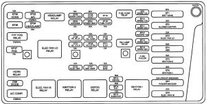
Deawoo Leganza - fuse box diagram - engine compartment
Deawoo Leganza – fuse box diagram – engine compartment

Passenger compartment fuse box

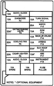
Deawoo Leganza - fuse box diagram - passenger compartment
Deawoo Leganza – fuse box diagram – passenger compartment

Fuse chart

Fuse number Ampere rating [A] Source Circuit protected
EF1 (Engine Fuse) 30 B+ Fuses F1 , F2, F4
EF2 30 B+ Blower Motor Relay, Blower Motor, Auto. Temp. Control Relay, ATC Controller
EF3 20 B+ Cooling Fan (Low) Relay, Aux. Cooling Fan, Cooling Fan Control Relay
EF4 60 B+ ABS Relay, Electronic Brake Control Module
EF5 30 B+ lgn 2 (lgn Key}, Starter
EF6 30 B+ lgn 1 (lgn Key), Ace, F17, F18
EF7 20 B+ lgn 2 Relay, EF 32, Keyless Entry System, Sun Roof, Power Window Main Switch
EF8 20 B+ Cooling Fan (High) Relay, Cooling Fan Control Relay, Main Cooling Fan
EF12 15 B+ Hazard Switch
EF15 30 B+ Rear Window Defogger, Defogger Relay, EF27
EF16 20 B+ Generator Terminal F, Electronic Ignition System Coil, Evaporativer Emission Canister Purge Solenoid, Engine Control Module
EF17 15 B+ Fuel Injectors, EGA
EF19 15 B+ Fuel Pump, DLC Connector E
EF20 10 B+ RH Parking Lamp, RH Taillamp, Dimmer Control Switch, Chime bell
EF21 10 B+ LH Parking Lamp, LH Taillamp, License Lamp
EF22 15 B+ Engine Control Module
EF23 20 B+ Brake Switch, Brake Lamps, EBCM, Cruise Control, BTSi
EF24 20 B+ Power Seat
EF25 10 EF34 Headlamp High RH
EF26 10 EF34 Headlamp Low RH
EF27 10 EF15 Electric Outside Rearview Mirror Defogger
EF28 15 B+ Auto Door Lock System
EF29 15 B+ Power Antenna, lgn Key Illumination, Luggage Compartment Lamp, Interior Courtesy Lamp, Door Step Lamp, Keyless Entry System Unit
EF30 10 EF34 Headlamp High LH
EF31 10 EF34 Headlamp Low LH
EF32 10 EF7 Electric Outside Rearview Mirror Control, Map Lamp (W/0 Sun Roof), Sun Roof Switch, Keyless Entry Unit
EF33 10 B+ NC Compressor Relay, NC Compressor, NC Diode
EF34 25 B+ Headlamp Relay, EF30, EF25, EF31 , EF26, High Beam Indicator Switch, Illumination Relay, Headlamp Switch, Anti-Theft Siren
EF35 10 B+ Horn System
EF37 15 B+ Fog Lamp Relay, LH and RH Front Fog Lamps
F1 (Fuse) 10 EF1 Audio System, Clock, Key Remind Switch, Chime Module, Ashtray Ilium., Door Switch, ATC Controller
F2 10 EF1 DLC
F4 20 EF1 Daytime Running Lamps
F6 20 EF5 (Ign 2) lgn 2 Relay, Cooling Fan (High) Relay, Cooling Fan (Low) Relay, A/C Compressor Relay, A/C Switch, Cooling Fan Control Relay, ECM., Blower Motor Relay, Auto. Temp. Control Relay, Defogger Relay, ATC Controller
F8 20 EF6 (Acc) Cigar Lighter, Glove Box Lamp, Glove Box Switch, Key Interlock Solenoid
F9 10 EF6 (Acc) Audio System, Clock
F11 15 EF6 (Ign 1) Turn Signal/Hazard Switch, Daytime Running Lamps
F12 25 EF6 (Ign 1) Wiper/Washer System
F13 15 EF6 (Ign 1) Engine Control Module, lgn 1 Relay, Vehicle Speed Sensor, Fuel Pump Relay, CMP
F14 10 EF6 (Ign 1) Backup Switch, Backup Lamps, Defogger, ATC Controller, Seat Belt Switch, Cruise Control Systell’
F15 10 EF6 (Ign 1) Supplemental Inflatable Restraint System
F16 20 EF6 (Ign 1) Sun Roof Module, Sun Roof Motor (if equipped)
F17 10 EF6 (Ign 1) Electronic Brake Control Module
F18 10 EF6 (Ign 1) Instrument Cluster, Chime Module, Brake Switch, ATC. Controller, Vehicle Speed Sensor, ECM, Brake Transaxle Shift Interlock Solenoid, Transmission Range Switch, Speed Sensitive Power Steering Module, EBCM

WARNING: Terminal and harness assignments for individual connectors will vary depending on vehicle equipment level, model, and market.

Deawoo Lanos (1999 – 2002) – fuse box diagram

Deawoo Lanos (1999 – 2002) – fuse box diagram

Year of production: 1999, 2000, 2001, 2002

Engine compartment fuse box

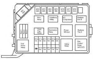
Deawoo Lanos - fuse box diagram - engine compartment
Deawoo Lanos – fuse box diagram – engine compartment

Passenger compartment fuse box

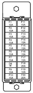
Deawoo Lanos - fuse box diagram - passenger compartment
Deawoo Lanos – fuse box diagram – passenger compartment

Fuse chart

Fuse number Ampere rating [A] Source Circuit protected
EF1 (Engine Fuse) 80 BAT Engine Fuses EF15 to EGF20 and Fuses F1 to F7
EF2 30 BAT Ignition Switch, ACC (F9 and F10) and IGN 1 (F11 to F17)
EF3 30 BAT Ignition Switch, START and IGN2 (F18, F19, F20)
EF4 30 BAT Radiator Fans
EF5 30 BAT Power Windows, Sunroof Module
EF6 40 BAT Antilock Brakes
EF7 30 BAT Rear Window Defogger
EF8 30 BAT Hi Blower
EF10 20 EF19 Headlamp Hi Beam
EF11 10 EF19 Headlamp Lo Beam (Left Side)
EF12 10 EF19 Headlamp Lo Beam (Right Side)
EF13 10 EF20 Tail and Illumination Lamps (Left Side)
EF14 10 EF20 Tail and Illumination Lamps (Right Side)
EF15 15 EF1 Front Fog Lamp
EF16 15 EF1 Fuel Pump Relay
EF17 10 EF1 Horn, Anti-Theft Siren
EF18 10 EF1 A/C Compressor
EF19 25 EF1 Hi Beam Passing, Daytime Running Lamps
EF20 20 EF1 EF13, EF14
F1 (Fuse) 10 EF1 Interior courtesy Lamp, Luggage Compartment Lamp, ESDS
F2 10 EF1 Clock, Door Open Warning, DLC, Headlamp Combinantion Switch, Key Reminder Switch
F3 15 EF1 Hazard Lamp
F4 15 EF1 Door Lock, Keyless Entry Module
F5 10 EF1 ABS, PCM/ECM
F6 10 EF1 Audio
F7 15 EF1 Stoplamp, Center Highj-Mounted Stoplamp
D8 (Diode)
F9 10 ACC Audio, Key Interlock system
F10 15 ACC Cigar Lighter
F11 10 IGN 1 Instrument Cluster, Clock, Daytime Running Lamps, Chime Module
F12 10 IGN 1 Backup Lamp, Keyless Entry Module
F13 15 IGN 1 Supplemental Inflatable Restraints
F14 15 IGN 1 Injectors, Generator, EGR Valve, Vehicle Speed Sensor, EVAP Canister Purge Valve, Post-Converter Oxygen Sensor, Camshaft Position Sensor, PCM/ECM
F15 15 IGN 1 Ignition Control Module
F16 15 IGN 1 Turn Signal Lamp, Electric Outside Rearview Mirrors
F17 15 IGN 1 PCM/ECM, ABS Warning Lamp, Variable Geometry Induction Solenoid
F18 20 IGN 2 Wiper/Washer System
F19 10 IGN 2 Power Window Relay, A/C Compressor Relay, Radiator Fan Relays, Defogger relay, ABS Relay, Sunroof switch
F20 20 IGN 2 Blower Position 1,2,3

WARNING: Terminal and harness assignments for individual connectors will vary depending on vehicle equipment level, model, and market.

Deawoo Lanos (1997 – 1998) – fuse box diagram

Deawoo Lanos (1997 – 1998) – fuse box diagram

Year of production: 1997, 1998

Engine compartment fuse box

Deawoo Lanos - fuse box diagram - engine compartment
Deawoo Lanos – fuse box diagram – engine compartment

Passenger compartment fuse box

Deawoo Lanos - fuse box diagram - passenger compartment
Deawoo Lanos – fuse box diagram – passenger compartment

Fuse chart

Fuse number Ampere rating [A] Source Circuit protected
EF1 (Engine Fuse) 80 BAT Engine Fuses EF15 to EGF20 and Fuses F1 to F7
EF2 30 BAT Ignition Switch, ACC (F9 and F10) and IGN 1 (F11 to F17)
EF3 30 BAT Ignition Switch, START and IGN2 (F18, F19, F20)
EF4 30 BAT Radiator Fans
EF5 30 BAT Power Windows
EF6 40 BAT Antilock Brakes
EF7 30 BAT Rear Window Defogger
EF8 30 BAT Hi Blower
EF10 20 EF19 Headlamp Hi Beam
EF11 10 EF19 Headlamp Lo Beam (Left Side)
EF12 10 EF19 Headlamp Lo Beam (Right Side)
EF13 10 EF20 Tail and Illumination Lamps (Left Side), Headlamp Lewveling, Rear Fog Lamps
EF14 10 EF20 Tail and Illumination Lamps (Right Side)
EF15 15 EF1 Front Fog Lamp
EF16 15 EF1 Fuel Pump
EF17 10 EF1 Horn
EF18 10 EF1 A/C Compressor
EF19 25 EF1 Hi Beam Passing
EF20 20 EF1 Illumination Lamp
F1 (Fuse) 10 EF1 Rear Fog, Room Lamp, Trunk Room Lamp
F2 10 EF1 Clock, Door Open Warning, ALDL, Headlamp Relay, Illumination Lamp Relay, Engine Immobilizer
F3 15 EF1 Hazard Lamp
F4 15 EF1 Door Lock
F5 10 EF1 ABS, ECM, TCM
F6 10 EF1 Audio, Antenna Motor
F7 15 EF1 Stoplamp, Center Highj-Mounted Stoplamp
D8 (Diode)
F9 10 ACC Audio
F10 15 ACC Cigar Lighter
F11 10 IGN 1 Instrument Cluster, Clock, Defog Relay, Seat Belt Switch, Engine Immobilizer
F12 10 IGN 1 Backup Lamp
F13 15 IGN 1 Supplemental Inflatable Restraints
F14 15 IGN 1 Injectors, Altenrator, Starter Solenoid, Transaxle Solenoids, Vehicle Speed Sensor, Tachometer, Canister Purge Solenoid
F15 15 IGN 1 DIS Ignition Coil
F16 15 IGN 1 Turn Signal Lamp, Mirror Switch
F17 15 IGN 1 ECM, TCM, ABS Warning Lamp, Fuel Pump Relay, Variable Induction Geometry Solenoid
F18 20 IGN 2 Wiper/Washer
F19 10 IGN 2 Power Window Relay, A/C Compressor Relay, Radiator Fan Relays, Defog relay, ABS Relay
F20 20 IGN 2 Blower Position 1,2,3

WARNING: Terminal and harness assignments for individual connectors will vary depending on vehicle equipment level, model, and market.

Land Rover Range Rover Velar (2018) – fuse box diagram

Land Rover Range Rover Velar (2018) – fuse box diagram

Year of production: 2018

Engine compartment fuse box

Front fuse box

Fuse number Ampere rating [A] Circuit protected
1 5 Left-side headlight motor
2 5 Headlights
3 5 Right-side headlight motor
4
5
6 30 Headlight power wash
7 25 Left-side headlight
8 25 Right-side headlight
9 10 Front fog lights
10 15 Intercooler water pump

Rear fuse box

Fuse number Ampere rating [A] Circuit protected
11 15 Engine management system
12 15 Engine management system
13 10 Gear selector. Fuel system. Engine management system
14 10 Engine management system (2.0L gasoline)
15 Engine management system (2.0L diesel)
15 10 Engine cooling. Engine mounts. Engine management system
16 25 Engine management system
17 10 Exhaust sensors (2.0L gasoline)
20 Exhaust sensors (2.0L diesel)
18 20 Exhaust sensors (2.0L diesel, 3.0L gasoline)
19 20 Exhaust sensors (3.0L gasoline)
20 15 Engine management system
21
22 5 Intercooler water pump
23 5 Engine management system. Starter motor. Electrical power management
24 15 Transmission control module
25 30 Starter motor
26
27 25 Transfer box
28 30 Fuel pump

Passenger compartment fuse box

Fuse number Ampere rating [A] Circuit protected
1 20 Sunroof
2 5 Brake pedal switch
3 5 Vehicle immobilizer
4 5 Diagnostic socket
5 5 Battery back-up sounder
6 20 Second row auxiliary power socket
7 20 Cubby box auxiliary power socket
8 20 Left-side front seat
9 20 Right-side front seat
10 30 Left-side front seat
11 30 Right-side front seat
12 30 Side steps
13 20 Front auxiliary power socket
14 20 Rear seat recline
15
16 5 Electrical supply
17 5 Door handle antennas
18 15 Horns
19
20 20 Driver’s heated seat. Driver’s climate seat
21 20 Front passenger’s heated seat. Front passenger’s climate seat
22 25 Right-side front door module
23 25 Left-side rear door module
24 25 Right-side rear door module
25 25 Left-side front door module
26
27 5 Climate system ionizer
28 10 Steering angle sensor
29 5 Keyless entry
30 20 Keyless entry
31
32 5 Tire Pressure Monitoring System (TPMS)
33 15 Air Conditioning (A/C)
34 10 USB socket
35


Loadspace fuse box

Upper fuse box:

Fuse number Ampere rating [A] Circuit protected
1 20 Loadspace auxiliary power socket
2 5 Heated rear seats
3 20 Left-side heated rear seat
4 20 Right-side heated rear seat
5 10 Dynamic Stability Control (DSC). Electronic differential
6 10 Instrument panel
7 5 Electrical power management
8 25 Trailer socket
9 10 Diesel Exhaust Fluid (DEF)
10 25 DEF
11 10 Rear-view mirror. Camera
12 10 Entertainment system
13 10 Heated steering wheel
14
15 5 Camera
16 5 Adaptive Surface Response (AdSR)
17 5 Adaptive cruise control
18 20 Trailer socket
19 15 AdSR
20 10 Telematics
21
22 15 Driver’s door switches. Driver’s seat. Driver’s seat switches. Front passenger’s seat
23 10 Rear sun blind
24 20 Rear auxiliary power socket
25
26 15 Rear wiper
27 30 Trailer
28 30 Fuel system
29 30 Powered tailgate
30 5 Fuel pump (2.0L diesel)


Lower fuse box:

Fuse number Ampere rating [A] Circuit protected
1 15 Touch screen. Climate control panel
2 10 Audio amplifier
3 10 Gesture tailgate
4 10 Navigation. Television tuner
5 15 Audio head unit
6 15 Portable media connector panel
7
8
9
10
11
12
13
14
15 15 Heating and ventilation
16 20 Auxiliary heater

WARNING: Terminal and harness assignments for individual connectors will vary depending on vehicle equipment level, model, and market.

Land Rover Range Rover Sport (2018) – fuse box diagram

Land Rover Range Rover Sport (2018) – fuse box diagram

Year of production: 2018

Engine compartment fuse box

Fuse number Ampere rating [A] Circuit protected
1 10 Auto stop/start (hybrid vehicles only)
2
3 15 Hybrid vehicle powertrain
4 15 Hybrid vehicle powertrain
5 10 Hybrid vehicle powertrain
6
7
8
9 25 Rear screen washer
10 15 Front fog lights
11 15 Horn
12 30 Right-side headlight washer pump
13 30 Left-side headlight washer pump
14 15 Auto stop/start
15 15 Supercharger cooling
16 25 Windshield washer jets
17 10 Engine management system
18 20 Engine management system (gasoline only)
19 15 Engine management system
20 25 Engine management system
21 20 Engine management system
22 10 Engine management system. Engine cooling fan (gasoline only)
23 10 Engine management system
24 15 Engine management system
25 10 Engine management system (diesel only)
26
27
28
29 5 Engine management system. Starter motor. Electrical power management
30 10 Heated wiper park
31
32 10 Steering wheel
33 5 Transfer box
34 5 Right-side Adaptive Front lighting System (AFS)
35 5 Headlamp leveling
36 5 Left-side Adaptive Front lighting System (AFS)
37
38
39 5 Hybrid vehicle powertrain
40 15 Transmission. Terrain response switch. Gear selector
41
42 25 Left-side headlight
43 5 Hybrid vehicle powertrain
44 25 Right-side headlight
45
46
47
48
49 5 Engine management system
50
51 10 Engine management system
52
53
54
55
56
57
58
59
60 5 Heated wiper park

Passenger compartment fuse box

Fuse number Ampere rating [A] Circuit protected
1 20 Front cigar lighter
2 20 Front accessory socket. Rear accessory socket
3 20 Rear accessory socket
4 20 Rear accessory socket. USB sockets
5
6 10 Climate control (hybrid vehicles only)
7 5 Battery back-up sounder
8 15 Auxiliary heater (hybrid vehicles only)
9
10 20 Accessory sockets
11 30 Right-side rear seats
12 20 Panoramic roof
13 20 Panoramic roof
14 5 All Terrain Progress Control (ATPC)
15
16
17
18 30 Left-side rear seat
19
20 25 Left-side rear door
21 10 Cool box
22
23 20 Front passenger’s seat. Left-side rear seat
24 25 Driver’s door switches. Driver’s door soft close
25 15 Dynamic Stability Control (DSC)
26 10 Passenger’s seat switches
27 5 Tire Pressure Monitoring System (TPMS). Front overhead console
28 20 Driver’s seat
29 25 Right-side rear door switches
30 20 Panoramic roof
31
32 10 Charging port flap
33 30 Driver’s seat
34 25 Passenger door switches. Passenger door soft close
35 5 Brake pedal switch
36
37
38
39
40
41 5 Telematics
42
43 10 Heated steering wheel
44 10 Steering wheel
45 5 Touchscreen buttons. Rear climate control
46 15 Climate control
47
48
49 5 Vehicle immobilizer
50
51
52 5 Air ionizer
53
54 5 Diagnostic socket
55
56 10 Climate control


Loadspace fuse box

Fuse number Ampere rating [A] Circuit protected
1 15 Hybrid vehicle powertrain
2 25 Third row heated seats
3 15 Third row seat switches
4
5
6
7 5 Electrical power management
8 20 Driver’s heated seat
9 15 Driver’s and front passenger seat switches
10 20 Front passenger’s heated seat
11 20 Right-side rear heated seat
12 15 Flashlight
13 20 Left-side rear heated seat
14 20 Rear wiper
15 30 Fuel system
16 15 Trailer socket
17 10 Diesel Exhaust Fluid (DEF)
18 20 Accessory power socket
19 20 Rear cigar lighter
20 20 Cubby accessory socket. Third row USB socket
21 20 Loadspace accessory socket
22 22 Hybrid vehicle powertrain
23 10 Lower touchscreen
24 10 Instrument panel
25 5 Air suspension
26
27 10 Parking aid. Rear-view mirror. Cameras. Blind spot assist
28 10 Head-Up Display (HUD)
29 5 Adaptive Cruise Control
30 30 Heated rear screen. Radio Frequency filter
31
32
33 15 Rear wiper
34
35
36
37 30 Driver’s seat
38
39 30 Deployable side steps
40 10 External sound generator (hybrid vehicles only)
41
42 20 Right-side rear seat
43 20 Keyless locking
44 15 Trailer socket
45 15 Engine management system. Fuel system
46 15 Fuel system
47
48 10 Touchscreen
49 10 Gesture tailgate
50 15 Entertainment and information systems
51 15 Entertainment and information systems
52 10 Portable media
53 10 Portable media
54
55 15 Air suspension
56 10 Air suspension
57 5 Keyless locking
58 30 Front passenger’s seat. Left-side rear seat
59 5 Rear-view camera
60 10 Adaptive cruise control

WARNING: Terminal and harness assignments for individual connectors will vary depending on vehicle equipment level, model, and market.